/
Workability of Metals Workability is defined as the extent to which a Workability of Metals Workability is defined as the extent to which a

Workability of Metals Workability is defined as the extent to which a - PDF document

natalia-silvester
natalia-silvester . @natalia-silvester
Follow
387 views
Uploaded On 2016-08-25

Workability of Metals Workability is defined as the extent to which a - PPT Presentation

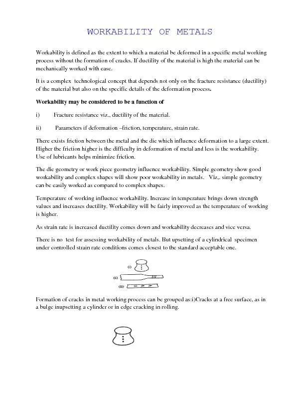
iiCracks that develop in a surfacewhere iii interface friction is high as in extrusion Internal cracks as in drawn bars Worka ID: 456394

ii)Cracks that

Share:

Link:

Embed:

Download Presentation from below link

Download Pdf The PPT/PDF document "Workability of Metals Workability is def..." is the property of its rightful owner. Permission is granted to download and print the materials on this web site for personal, non-commercial use only, and to display it on your personal computer provided you do not modify the materials and that you retain all copyright notices contained in the materials. By downloading content from our website, you accept the terms of this agreement.


Presentation Transcript

Workability of Metals Workability is defined as the extent to which a material be deformed in a specific metal working process without the formation of cracks. If ductility of the material is high the material can be ii)Cracks that develop in a surfacewhere iii) interface friction is high as in extrusion . Internal cracks as in drawn bars. Workability Limit Diagram(WLD) There exists a unique correlation between tensile strain and compressive strains at fracture for each material, at room temperature as shown in figure . This relationship is used as the fracture criteria. In the figure Strain Paths and Fracture Limit Line for a given material is plotted . For different values of compression strain at fracture the corresponding tensile strain is obtained and is plotted for different materials to get the WLD. Now the process parameter represented by strain paths at potential fracture sites in the material is plotted.Strain paths can be determined either experimentally or by using FEA models. Soft materials like plasticine, lead or pure aluminium are taken and grids are placed on it and subjected to strain . The strain paths are determined from the path traced out by the deformation. These are then plotted in the diagram. If the strain paths in the deformation of the material exceeds the fracture limit line, then fracture will occur.Strain paths depend on the die geometry, work piece geometry, lubrication condition and material property. Consider cold upsetting of a cylinder into a blot head. A cylindrical specimen of dia ‘d’ is upset to a head of diameter ’D’. To form a head of diameter ‘D’ from diameter ‘d’ requires the material to withstand a circumferential surface strain of In(D/d). For workability of the material, the strain path must reach this limiting value of strain without crossing the fracture limit line. In figure the strain path (a) meets the fracture limit line before reaching the limiting value. Fracture will take place in the material. By improving the lubrication the stress path can be shifted to (b) and the deformation can be achieved without fracture. Alternately, deformation can be made with strain path (a) by changing the material from A to the more workable material B with fracture limit line as shown in the figure. Residual Stresses in wrought Products Residual stresses are due to the presence of stresses in the material after the completion of mechanical working. After mechanical working the desired shape in the metal is obtained, the external forces are removed. Now, if the mechanically worked metal has stresses in it then they are referred to as “Residual Stresses”. These stresses are the result of non uniform plastic deformation. For example, In rolling of sheets, plastic flow of metal occurs predominantly near the surface. Due to rolling action, the surface grains are deformed and elongated, while the grains at the center of the sheet are unaffected. Since the sheet must remain one continuous unit, the surface and center regions of the sheet must undergo strain accommodation. The center fibers tries to restrain the outer fiber from stretching while the outer fibers tend to stretch the central fiber. This results in Residual Stresses which consists of a high compressive stress at the surface and a tensile residual stress at the center of the sheet. Inhomogeneous deformation has occurred. In general, the direction of residual stresses induced in the metal (due to inhomogeneous deformation) will be opposite to the direction of plastic strain that produced residual stress. Residual stresses are only elastic stresses. The maximum value it can reach is yield strength of the material. Components with residual stresses can be stress relieved at a predetermined temperature. Even non uniform heating or cooling can produce residual stresses in the same way as non uniform plastic deformation. In general, the direction of residual stresses induced in the metal (due to inhomogeneous deformation) will be opposite to the direction of plastic strain that produced residual stress. Residual stresses are only elastic stresses. The maximum value it can reach is yield strength of the material. Components with residual stresses can be stress relieved at a predetermined temperature. Even non uniform heating or cooling can produce residual stresses in the same way as non uniform plastic deformation. To form a head of diameter ‘D’ from diameter ‘d’ requires the material to withstand a circumferential surface strain of In(D/d). For workability of the material, the strain path must reach this limiting value of strain without crossing the fracture limit line. In figure the strain path (a) meets the fracture limit line before reaching the limiting value. Fracture will take place in the material. By improving the lubrication the stress path can be shifted to (b) and the deformation can be achieved without fracture. Alternately, deformation can be made with strain path (a) by changing the material from A to the more workable material B with fracture limit line as shown in the figure. Residual Stresses in wrought Products Residual stresses are due to the presence of stresses in the material after the completion of mechanical working. After mechanical working the desired shape in the metal is obtained, the external forces are removed. Now, if the mechanically worked metal has stresses in it then they are referred to as “Residual Stresses”. These stresses are the result of non uniform plastic deformation. For example, In rolling of sheets, plastic flow of metal occurs predominantly near the surface. Due to rolling action, the surface grains are deformed and elongated, while the grains at the center of the sheet are unaffected. Since the sheet must remain one continuous unit, the surface and center regions of the sheet must undergo strain accommodation. The center fibers tries to restrain the outer fiber from stretching while the outer fibers tend to stretch the central fiber. This results in Residual Stresses which consists of a high compressive stress at the surface and a tensile residual stress at the center of the sheet. Inhomogeneous deformation has occurred. ii)Cracks that develop in a surfacewhere iii) interface friction is high as in extrusion .Internal cracks as in drawn bars. Workability Limit Diagram(WLD) There exists a unique correlation between tensile strain and compressive strains at fracture for each material, at room temperature as shown in figure . This relationship is used as the fracture criteria. In the figure Strain Paths and Fracture Limit Line for a given material is plotted . For different values of compression strain at fracture the corresponding tensile strain is obtained and is plotted for different materials to get the WLD. Now the process parameter represented by strain paths at potential fracture sites in the material is plotted.Strain paths can be determined either experimentally or by using FEA models. Soft materials like plasticine, lead or pure aluminium are taken and grids are placed on it and subjected to strain . The strain paths are determined from the path traced out by the deformation. These are then plotted in the diagram. If the strain paths in the deformation of the material exceeds the fracture limit line, then fracture will occur.Strain paths depend on the die geometry, work piece geometry, lubrication condition and material property. Consider cold upsetting of a cylinder into a blot head. A cylindrical specimen of dia ‘d’ is upset to a head of diameter ’D’. Workability is defined as the extent to which a material be deformed in a specific metal working process without the formation of cracks. If ductility of the material is high the material can be mechanically worked with ease. It is a complex technological concept that depends not only on the fracture resistance (ductility) of the material but also on the specific details of the deformation process. Workability may be considered to be a function of i)Fracture resistance viz., ductility of the material. ii) Parameters if deformation –friction, temperature, strain rate. There exists friction between the metal and the die which influence deformation to a large extent. Higher the friction higher is the difficulty in deformation of metal and less is the workability. Use of lubricants helps minimize friction. The die geometry or work piece geometry influence workability. Simple geometry show good workability and complex shapes will show poor workability in metals. Viz,. simple geometry can be easily worked as compared to complex shapes. Temperature of working influence workability. Increase in temperature brings down strength values and increases ductility. Workability will be fairly improved as the temperature of working is higher. As strain rate is increased ductility comes down and workability decreases and vice versa. There is no test for assessing workability of metals. But upsetting of a cylindrical specimen under controlled strain rate conditions comes closest to the standard acceptable one. Formation of cracks in metal working process can be grouped as:i)Cracks at a free surface, as in a bulge inupsetting a cylinder or in edge cracking in rolling. WORKABILITY OF METALS