/
Exploring the  Nanoworld Exploring the  Nanoworld

Exploring the Nanoworld - PowerPoint Presentation

neoiate
neoiate . @neoiate
Follow
344 views
Uploaded On 2020-07-01

Exploring the Nanoworld - PPT Presentation

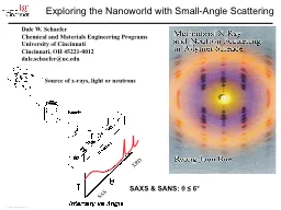
with SmallAngle Scattering Dale W Schaefer Chemical and Materials Engineering Programs University of Cincinnati Cincinnati OH 452210012 daleschaeferucedu Braggs Law and wave interference ID: 791997

length scattering silica small scattering length small silica angle space fractal morphology density real structure amp schaefer surface polymer

Share:

Link:

Embed:

Download Presentation from below link

Download The PPT/PDF document "Exploring the Nanoworld" is the property of its rightful owner. Permission is granted to download and print the materials on this web site for personal, non-commercial use only, and to display it on your personal computer provided you do not modify the materials and that you retain all copyright notices contained in the materials. By downloading content from our website, you accept the terms of this agreement.


Presentation Transcript

Slide1

Exploring the Nanoworld with Small-Angle Scattering

Dale W. Schaefer

Chemical and Materials Engineering ProgramsUniversity of CincinnatiCincinnati, OH 45221-0012dale.schaefer@uc.edu

Braggs Law and wave interferenceWhy do Small-Angle Scattering?Imaging vs. ScatteringBasic Concepts Cross SectionScattering Vector, Fourier Trns.Scattering Length Density Particle ScatteringGuinier ApproximationPorod’s LawFractal StructuresNanocomposites

SAXS & SANS:

θ

≤ 6°

XRD

SAS

Source of x-rays, light or neutrons

Slide2

Crystals: Bragg’s Law and the scattering vector,

q

θ

d

Ordered Structures give peaks in

reciprocal” Space.

Large structures scatter at small angles.The relevant size scale is determined by 2π/q q is a vector.You can’t always determine the real space structure from the scattering data.

Problem: Nanomaterials are seldom ordered

SAXS:

θ

<

real space

source

detector

Reciprocal space

Slide3

Disordered Structures in

“Real Space”

10

µmAgglomeratesPrimary ParticlesAggregatesPrecipitated Silica(NaO) (SiO

2)3.3 + HCl —> SiO2 + NaCl

10 nm

Water Glass

Complex

HierarchicalDisordered

Difficult to quantify structure from images.

Slide4

Hierarchical Structure from Scattering

100,000 nm

200 nm

0.5 nm10 nm

AgglomerateAggregate

PrimaryParticleNetwork“Polymer”

Four Length Scales

Four Morphology ClassesExponents related tomorphology

10

-7

10

-6

10

-5

0.0001

0.001

0.01

0.1

1

10

Intensity

-4.0

-2.0

-3.1

R

G

= 89

μ

q

-1

] ~

Length

-

1

~ sin(

θ

/2)

USAS

SAS

Slide5

Why Reciprocal Space?

10 µm

Isotactic polystyrene foams prepared by TIPS

Jim

Aubert

, SNL

Ultra-small-angle neutron scattering: a new tool for materials research. Cur. Opinion Sol. State & Mat Sci, 2004. 8(1): p. 39-47.

Images miss similarity

Slide6

Adding up the Phases

r

2

r3r4Electron density distribution n(r) = number of electrons in a volume element dr = dx dy dz around point r.

Scattering length density distribution ρ(r) = scattering length in a volume element d

r = dx dy dz around point r.

ρ(r) = bn(r)Many electrons

Amplitude is the Fourier transform of the SLD distribution (almost)

r1

scattering length of one electron

Slide7

Scattering Length Density (SLD) Distribution

Fourier transform of

the scattering length

density distributionρ(r)Can’t be measured

ρ(r)

What we measure: Square of the Fourier transform of the SLD distributionCan’t be inverted

Slide8

Characterizing Disordered Systems in Real Space

r

Real space

ξElectron Density Distribution

Correlation Function of theElectron Density DistributionDepends on latitude and longitude.Too much information to be useful.

Depends on separation distance.Retains statistically significant info.rResolution problems at small rOpacity problems for large r2-dimensionalOperator prejudiceThrow out phase information×

Problems with real space analysis

Slide9

Imaging vs. Scattering

r

q

Real space

Reciprocal space

ξ

ξ-1Schaefer, D. W. & Agamalian, M. Ultra-small-angle neutron scattering: a new tool for materials research. Curr Opin Solid St & Mat Sci 8, 39-47, (2004).Pegel, S., Poetschke

, P., Villmow, T., Stoyan, D. & Heinrich, G. Spatial statistics of carbon nanotube polymer composites. Polymer 50, 2123-2132, (2009).

Slide10

Differential Scattering Cross Section

sample

θ = scattering angle

Plane wave J0

Spherical wave JΩ

Spherical wave: Flux JΩ = energy/unit solid angle/s or photons/ unit solid angle /sPlane wave: Flux J0 = energy/unit area/s or photons/unit area/s

Slide11

What do we really measure?

length

Area

beamScattering cross section depends on sample size: BadOften called the scattering cross section or the intensity

Slide12

Scattering from Spherical Particle(s)

2

R

ρov = particle volumeI(q) ~ N(ρ - ρo)2v2P(q)solvent SLDForm Factor

N particles

Slide13

Particles in Dilute Solution

ρ

1

ρ2RVR

1 particle

Slide14

Small-Angle Scattering from Spheres

Large object scatter at small angles

Silica in Polyurethane

AFMGuinier RegimePorod (power-law) RegimeDiameter = 140 Å3 mm

Petrovic

, Z. S. et al. Effect of silica nanoparticles on morphology of segmented polyurethanes. Polymer 45, 4285-4295, (2004)

Slide15

Guinier Radius

Initial curvature is a measure of length

R

g ~ 1/qDerived in 5.2.4.1

Slide16

Guinier Fits

Slide17

Dense packing: Correlated Particles

Packing Factor

=

k

=

8 ϕPacking Factor ≅ 6

ξRÅÅ

Slide18

Colloidal Silica in Epoxy

50 nm

Exclusion zone

EPON 862 + Cure

W+ Silica

Chen, R.S.

et al,

Highly dispersed nanosilica-epoxy resins with enhanced mechanical properties Polymer, 2008. 49(17): p. 3805-3815.

Slide19

Using RG: Agglomerate Dispersion

19

Light Scattering

sonicate

hard agglomerate

dry

3.5 µm

D.W. Schaefer, D. Kohls and E.

Feinblum

,

Morphology of Highly Dispersing Precipitated Silica: Impact of Drying and Sonication.

J

Inorg

Organomet

Polym

, 2012. 22(3): p. 617-623

.)

Slide20

Hierarchical Structure from Scattering

20

100,000 nm

200 nm0.5 nm10 nm

Agglomerate

AggregatePrimaryParticleNetwork“Polymer”

Four Length Scales

Four Morphology Classes

Exponents related tomorphology

10

-7

10

-6

10

-5

0.0001

0.001

0.01

0.1

1

10

Intensity

-4.0

-2.0

-3.1

R

G

= 89

μ

q

-1

] ~

Length

-

1

~ sin(

θ

/2)

USAXS

SAXS

Slide21

Mass

-Fractal Objects

Mass Fractal Dimension =

dReal SpaceM~Rd

Dispersion

d = 3d = 2M ~V ~ R3M ~V ~ R2M ~V ~ R1M ~V ~ R2.2

Slide22

Surface Fractal Dimension

S ~

R

ds

S ~ R

2

fractal or self-affine surface

Sharp interface

Slide23

Scattering from Fractal

Objects: Porod Slopes

d = Mass Fractal Dimension ds = Surface Fractal Dimension

Match at qR = 1

qR

= 1Large q

~ Sv/q-x

Small q

Slide24

Porod Slope for Fractals

Structure

Scaling Relation

Porod Slope= ds – 2dmdm = 3d

S = 2

- 4dm = 32 < d

S ≤ 3 - 3 ≤ Slope ≤ - 4

1 ≤ ds =

dm ≤ 3

- 1 ≤

Slope

≤ - 3

Smooth Surface

Rough Surface

Mass Fractal

I

(q

)

=

q

d

s

-2d

m

Slide25

Scattering from colloidal aggregates

R

r

Precipitated Silica

Log q

Log IqR = 1

qr = 1q-dq-4

Slide26

Morphology of Dimosil®

Tire-Tread Silica26

Two Agglomerate length Scales

Soft = Chemically BondedHard = Physically Bonded-2-4

7 µm

116 µm

300 nm

Light Scattering

USAXS

126 Å

Dispersion

Reinforcement

Schaefer

, D. W., Kohls, D. &

Feinblum

, E. Morphology of Highly Dispersing Precipitated Silica: Impact of Drying and Sonication.

J

Inorg

Organomet

Polym

22, 617–623 (2012).

Slide27

Aggregates are robust

27

Soft Agglomerates

Hard Agglomerates

Aggregates

What is the ideal aggregate size?

shear

R

agg

Slide28

Exploring the

Nanoworld

TubesCarbon NanotubesSheets

Layered Silicates

How valid are the cartoons?

What are the implications of morphology for

material properties?

Spheres

Colloidal Silica

1-d

2-d

3

-d

Answers come from Small-Angle Scattering.

Schaefer, D.W. and R.S. Justice,

How nano are nanocomposites?

Macromolecules, 2007. 40(24):

p

. 8501-8517.

Slide29

The Promise of Nanotube Reinforcement

α

= aspect ratio

Slide30

0.01% Loading CNTs

in Bismaleimide Resin

5000

Å-1)q(Å)

PD

LIGHT

-1

.00001

.001

10

SAXS

.1

Length

Diameter

Surface

Local

Structure

-1

-4

Intensity

Slide31

0.05% Carbon in Bismaleimide Resin

2000

Å

d

L

p

Worm-like branched cluster

Slide32

TEM of Nanocomposites

Hyperion MWNT in Polycarbonate

Pegel et al. Polymer (2009) vol. 50 (9) pp. 2123-2132

Slide33

Don’t Believe the Cartoons

Tubes

Carbon NanotubesSheets

Layered Silicates

Spheres

Colloidal Silica

1-d

2-d

3

-d

Schaefer, D.W. and R.S. Justice,

How nano are nanocomposites?

Macromolecules, 2007. 40(24):

p

. 8501-8517.

Slide34

Conclusion

If you want to determine the morphology of a disordered materialuse small-angle scattering.