/
Polyethylene Fittingsfor Gas  Water under pressure Polyethylene Fittingsfor Gas  Water under pressure

Polyethylene Fittingsfor Gas Water under pressure - PDF document

norah
norah . @norah
Follow
343 views
Uploaded On 2021-10-10

Polyethylene Fittingsfor Gas Water under pressure - PPT Presentation

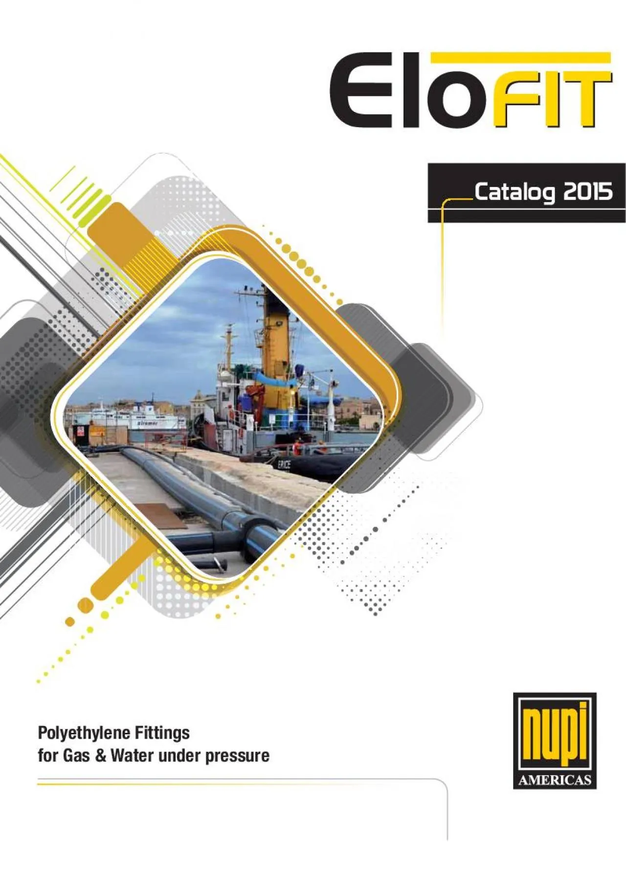
POLYETHYLENE2 PE PolyethyleneCATALOG 2015VALID FORM MARCH 2015PE Polyethylene 3POLYETHYLENETHE COMPANY GLOSSARY 1 ELOFIT POLYETHYLENE FITTINGS FOR GAS WATER UNDER PRESSUREELECTROFUSIO ID: 899632

ips polyethylene welding pipe polyethylene ips pipe welding pressure 6250 volume weightlb test 5000 ipsx1 pack npt0 spigot time

Share:

Link:

Embed:

Download Presentation from below link

Download Pdf The PPT/PDF document "Polyethylene Fittingsfor Gas Water unde..." is the property of its rightful owner. Permission is granted to download and print the materials on this web site for personal, non-commercial use only, and to display it on your personal computer provided you do not modify the materials and that you retain all copyright notices contained in the materials. By downloading content from our website, you accept the terms of this agreement.


Presentation Transcript

1  Polyethylene Fittingsfor Ga
 Polyethylene Fittingsfor Gas & Water under pressure POLYETHYLENE 2 PE Polyethylene CATALOG 2015VALID FORM MARCH 2015 PE Polyethylene 3 POLYETHYLENE THE COMPANY ...................................................................................................................GLOSSARY ......................................................................................................................1. ELOFIT - POLYETHYLENE FITTINGS FOR GAS & WATER UNDER PRESSUREELECTROFUSION COUPLER (230 PSI - IPS) ......................................................................................................................... 20............................... 21 ELECTROFUSION SEWAGE COUPLER (45 PSI - IPS)............................................................................................................. 22ELECTROFUSION COUPLER (380 PSI - IP

2 S) ....................................
S) ........................................................................................ELECTROFUSION END CAP (230 PSI - CTS) .........................................................................................ELECTROFUSION END CAP (230 PSI - IPS) .........................................................................................45° E/F ELBOW (230 PSI - IPS)..................................................................................................90° E/F ELBOW (230 PSI - IPS)..................................................................................................ELECTROFUSION EQUAL TEE WITH SPIGOT END (230 PSI - CTS) .....................................................................ELECTROFUSION EQUAL TEE WITH SPIGOT END (230 PSI - IPS) .....................................................................BUTT FUSION REPAIR SLEEVE

3 .......................................
....................................................................................................180° VARIABLE LENGTH REPAIR SLEEVE ...........................................................................................TOOLS FOR REPAIR SLEEVES INSTALLATION .......................................................................................TAPPING TEE WITH RIGID UNDERCLAMP (230 PSI) ..................................................................................TAPPING TEE WITH BELT (230 PSI)...................................................................................................................................... 33BELTS FOR TAPPING TEES CLAMPING ON DIPS PIPES .................................................................................TORQUE WRENCH FOR TAPPING TEE CAP ...................................................................

4 ........................HEXAGONAL KEY FO
........................HEXAGONAL KEY FOR TAPPING TEE ................................................................................................................................. 35TOP LOAD TAPPING TEE .................................................................................................................................................... 36POSITIONER FOR TOP LOAD SADDLES ........................................................................................................................ 39 POLYETHYLENE 4 PE PolyethyleneBRANCH SADDLE WITH BELT .......................................................................................................................................... 40BELTS FOR BRANCH SADDLES CLAMPING ON DIPS PIPES................................................................................................ 42HIGH VOLUM

5 E BRANCH SADDLE WITH BELTS ...........
E BRANCH SADDLE WITH BELTS ................................................................................................................. 43HIGH VOLUME TOP LOAD BRANCH SADDLE ................................................................................................................... 44REPAIR SADDLES WITH BELTS FOR MEDIUM SURFACES .................................................................................................. 45REPAIR SADDLE WITH BELTS FOR BIG SURFACES .......................................................................................................... 46TOP LOAD BRANCH SADDLE WITH VALVE FULL BORE .................................................................................................... 47SEWAGE E/F BRANCH SADDLE WITH GASKET ...........................................................................................

6 ..................... 48................
..................... 48..................... 49................. 52GEOTHERMAL SOCKET FUSION COUPLER ..................................................................................................................... 52 ..................................................................................................................... 53 ..................................................................................................................... 54PE/NPT STAINLESS STEEL FEMALE SOCKET FUSION ..................................................................................................... 55 .......................................................................................................................... 56 .......................................................................................................................... 57PE/NPT S

7 TAINLESS STEEL MALE SOCKET FUSION ....
TAINLESS STEEL MALE SOCKET FUSION ........................................................................................................ 58............... 59. 60......................... 60......... 61SOCKET FUSION END CAP ................. 63............ 63............. 64SOCKET FUSION 90° GEOTHERMAL ELBOW .................................................................................................................... 64.. 66LONG SPIGOT 90° ELBOW .................. 66LONG SPIGOT 45° ELBOW ................. 68LONG SPIGOT 90° TEE ....................... 70LONG SPIGOT WYE FITTING .............. 72LONG SPIGOT 90° REDUCING TEE ..... 73LONG SPIGOT REDUCER ................... 74LONG SPIGOT METRIC REDUCER ..... 78LONG SPIGOT STUB END .................. 80 POLYETHYLENE PE Polyethylene 5 LONG SPIGOT 55° BEVELED STUB END ...........................

8 ........................................
............................................................................................... 86MJ FLANGE ADAPTER WITH STIFFER SLEEVE ............................................................................................................. 90.......... 92................................ 92REVOLVING SCRAPER ...................... 93 ........................................................................................................................ 93..... 94ROTARY SCRAPER ............................ 95SCRAPER REPLACEMENT PARTS ........................................................................................................................................ 95ALIGNER WITH BELTS ....................... 96PIPE SUPPORT .................................. 96CLENAER FOR PE, PP, PVDF, PB ........ 97............. 97............. 98..............

9 .................... 98ADAPTER FOR DRILL
.................... 98ADAPTER FOR DRILLING MACHINE .................................................................................................................................... 99............................ 99MULTIFUNCTION WELDING UNIT INCORPORATED IN SUITCASEWITH BARCODE HAND SCANNER (LIGHT)..................... 101MULTIFUNCTION WELDING UNIT INCORPORATED IN SUITCASEWITH BARCODE HAND SCANNER ................................. 102MULTIFUNCTION - SMART - WELDING UNIT INCORPORATED IN SUITCASEWITH BARCODE HAND SCANNER (LIGHT)... 103MULTIFUNCTION - SMART - WELDING UNIT INCORPORATED IN SUITCASEWITH BARCODE HAND SCANNER................ 104AUTOMATIC MULTIFUNCTION WELDING UNIT WITH BARCODE SCANNER........................................................................ 105AUTOMATIC MULTIFUNCTION WELDING UNIT WITH BARCODE SCANNER (LIGHT)..................................

10 ......................... 10WELDING UNIT
......................... 10WELDING UNITS - ADDITIONAL EQUIPMENT AND SPARE PARTS ........................................... 107PAIR OF PINS ..................................................................................................................PAIR OF ADAPTER ..............................................................................................................BARCODE SCANNER ..............................................................................................................USB MEMORY DEVICE ..................................................................................................................................................... 108SOFTWARE CD AND BLUETOOTH USB PEN DRIVE FOR DATA DOWNLOAD ..................................................................... 108GLOBAL POSITIONING SYSTEM (GPS) ..................................

11 ........................................
........................................................................................... 108........................................... 109 POLYETHYLENE 6 PE Polyethylene2. ELOPRESS - COMPRESSION FITTINGS ..............................................................111TECHNICAL INFORMATION ............................................................................................................................................. 113ASSEMBLY INSTRUCTIONS ................. 113.................................................. 114FEMALE STRAIGHT ADAPTER .....................................................................................................MALE STRAIGHT ADAPTER ............................................................................................................................................ 115......................................

12 ........... 116.........................
........... 116......................................... 117.................................. 118.................................... 119EXAMPLE OF INSTALLATIONS .............................................................................................. 1213. ASSEMBLY INSTRUCTIONS ...............................................................................125 THE ELECTROFUSION PROCESS HOW TO READ THE BARCODES ........ PREPARATION OF THE PIPE ........ WELDING INSTRUCTIONS FOR ELECTROFUSION FITTINGS ................................................................................................................. PRESSURE TEST UNIT .................. COOLING TIMES AND PRESSURE TEST RECOMMENDATIONS ............................................................................................................ E/F COUPLERS Ø  6Ž, LONG COUPLERS, REDUCERS .

13 ........................................
........................................................................................................................ E/F COUPLERS Ø  8 ........................................................................................................................................................................ E/F TEES, REDUCED TEES, CAPS, 30°BENDS, 45°BENDS, 90°BENDS ................................................................................................ TAPPING TEES ................................................................................................................................................................................... ZERO LEAKAGE TAPPING TEES .......................................................................................................................................................... TAPPING VALVES ......

14 ........................................
........................................................................................................................................................................... BRANCH SADDLES ............................................................................................................................................................................. POLYETHYLENE PE Polyethylene 7 BAGGING SADDLES ............................................................................................................................................................................................. HIGH VOLUME BRANCH SADDLES FOR INSTALLATION WITH BELTS ................................................................................................................. POSITIONING TOOL FOR TOP LOAD BRANCH SADDLES, TAPPING TEES AND TAPPING VALVES ..............

15 ................................ TOP LO
................................ TOP LOAD BRANCH SADDLES (CODE 12EICOLTL142402) ........................................................................................................................ TOP LOAD TAPPING TEES (CODE 12EIPRESTL142402) ........................................................................................................................ TOP LOAD TAPPING VALVES (CODE 12EIPREVTL142402) .................................................................................................................... DRILLING MACHINE FOR USE ON BRANCH SADDLES ........................................................................................................................................ SAFETY FITTINGS (EXCESS FLOW VALVES) ........................................................................................................

16 ........................................
............................................... BUTT FUSION REPAIR PATCH .................................................................................................. REPAIR SADDLES WITH BELTS ................................................................................................. ELOFIT 180° VARIABLE LENGTH REPAIR SLEEVE (EIVLRS) ...................................................................... POLYETHYLENE 8 PE Polyethylene Registered Of“ ce & Headquarters - Busto Arsizio (VA) ItalyProduction, Operations & Administration Centre- Castel Guelfo di Bologna (BO) Italy parent company, S.p.A., was formed in Italy ago in the early 1970s. Relying on experience and constant growth, our company has proven to be a exible, cutting edge manufacturer, rea- In 2001, Nupige- by establishing Nupi Americas, Inc., a whollyowned subsidiary of Nup

17 igeco, with operations based in Houston,
igeco, with operations based in Houston, TX.NUPIGECO S.p.A. and Nupi Americas toge-ther develop and manufacture piping sy-stems for use in industrial, sanitary (plum-bing), HVAC, waterworks, gas, and irrigation Nupigecos Industrial division was established in 1995 to develop and produce ther-moplastic piping systems speci“ cally targeted to the oil and gas, chemical and petrochemical NUPIGECO S.p.A. offers a complete range of pipe and “ ttings made in advanced thermoplastic ma-NIRON, MULTINUPI, ELOFIT, ELOTHERM, ELOPRESS, POLYSYSTEM, POLYETHYLENE PIPES, MULTIGECO, SMARTFLEX, OILTECH, SUPER OILTECH, ELOWEB, ECOWAVE, NRGEO, covering a wide range of applica-tions, reducing costs, avoiding waste and incre-asing productivity. Due to their quality, these pro- catesand listings, in line with the regulations of the “ ve THE COMPANY POLYETHYLENE PE Polyethylene 9is

18 the goal, which is made easier everyday
the goal, which is made easier everyday by new technology. Nupigeco, S.p.A. is continuously , while strengthening our production systems, operated by a sophisticated techno-ducts. Our facilities use modern, state-of-the-art computer-controlled production equipment and methods, which together with . On these solid founda-tions Nupigeco and Nupi Americas demonstrate industry.rials and precise manufacture, obtained through continuous on-time deliveries, resulting in timely real time. Customer satisfaction is pursued stant attention to our customers needs , and by means of an effecti-ve team of people in post-sales service, effective and precise technical assistance, and intensive operations of NUPIGECO S.p.A. are located in Busto Arsizio near Milan, Italy.logna. NUPIGECO S.p.A. is present all over , with manufacturing facilities, a lia-ted companies and warehouses in TX

19 and New England (Nupi Americas), Brazil
and New England (Nupi Americas), Brazil, China, Australia, UAE, Germany, France, Spain, Belgium and the THE COMPANY Production, Operations & Administration Centre- Castel Guelfo di Bologna (BO) Italy POLYETHYLENE 10 PE Polyethylene Industrial avant-garde in the transport of liquid and gaseous fluids using systems made of plastic Sanitary systemsTransport of food fluidsPetroleum industryPetrochemical industry POLYETHYLENE PE Polyethylene 11 WHO WE ARE Our numbers Presence in the market for more than 30 years 22 product lines 300 employees 3 production plants in Italy 3 production plants in the world (Texas, Brazil, China) 26 extrusion lines in Italy, 2 lines in the U.S., 3 lines in China and 9 warehouses in Europe and the rest of the world (Germany, France, Spain, Belgium, UK, Texas, Brazil, China, UAE) 10% of turnover invest

20 ed in R & D 150,000 square meters of
ed in R & D 150,000 square meters of surface area occupied by NUPIGECO Exports established in more than 70 countries in 5 continents Worldwide after-sales assistance R & D department dedicated to Internal Development, Technical Support, After-Sales Service Production of pipes and fittings from ø ½" to ø 42" Training center for each authorized distributor POLYETHYLENE 12 PE Polyethylene GLOSSARY PolyethylenePolypropyleneNominal Diameter/Outside Diameter - Pipe or  tting external diameter in inchesWall thickness at any point around the circumference of a component rounded to the next greater 0,1mmStandard pressure rate. The design capacityOperation pressure recommended for general durability in handling and for use in typical water service installationsMirnimum required strength of a pipe or  ttingStandard Nominal Ratio: ratio of pipe outside

21 diameter to wall thicknessHydrostatic de
diameter to wall thicknessHydrostatic design stress (HDS=HDB/DSF) Design safety coe cient Hydrostatic design basis Fluid safety coe cient Temperature safety coe cientND, OD Pfa/PR POLYETHYLENE PE Polyethylene 13 Nupi Americas item codeNominal DiameterIt indicates the maximum value of weldability of the  tting on the pipe with the same DR or lower value.For tapping tees it indicates the dimension of the drilled hole. For branch saddles it indicates the usable hole size as declared by Nupi americasQuantity per box (*)Quantity per pallet (*)Item weight (lb)Item volume (ftSuitable for waterSewage (NOT suitable for the trasportation of human coonsuptio  uids)Factory Mutual (FM) Approval ProductsPack Weight lb/p.Volume ft/ p. POLYETHYLENE POLYETHYLENE FITTINGS FOR GAS & WATER 16 PE Polye

22 thylene POLYETHYLENE Weldable on pipe DR
thylene POLYETHYLENE Weldable on pipe DR 10 - 9 - 7Weldable on pipe DR 12.5 - 11.5 - 11 CodeTypePack.Weightlb/p.Volume/p.IDL1LDHH11/2Ž CTS 3026400.1100.00991/2Ž0.621.422.911.061.892.011Ž CTS4019200.1510.01481Ž1.121.422.911.592.40-   PE Polyethylene 17 POLYETHYLENE Weldable on pipe DR 11 - 10 Weldable on pipe DR 17 - 15.5 - 13.5 - 11 CodeTypePack.Weightlb/p.Volume/p.IDL1LDH3/4Ž IPS4019200.1620.01483/4Ž1.051.412.911.592.401Ž IPS4019200.1570.01481Ž1.311.412.911.792.401Ž 1/4 IPS3014400.2570.02081Ž 1/41.661.573.262.162.911Ž 1/2 IPS209600.3690.02971Ž 1/21.901.693.472.643.402Ž IPS167680.5780.03712Ž2.372.525.123.113.88200 PSI3Ž IPS323841.1890.08833Ž3.50 2.915.904.455.04200 PSI4Ž IPS222641.7400.12854Ž4.503.116.305.596.14200 PSI6Ž IPS24963.5380.31786Ž6.623.517.097.998.41200 PSI8Ž IPS24489.1300.74878Ž8.624.298.6610.9411.01200 PSI   ELECTROFUSION FI

23 TTINGS 18 PE Polyethylene POLYETH
TTINGS 18 PE Polyethylene POLYETHYLENE Weldable on pipe DR 17 - 15.5 - 13.5 - 11 - 9.3 - 9 - 7.3With pre-heating bar code CodeTypePack.Weightlb/p.Volume/p.IDDD2L10Ž IPS17122420.7171.497410Ž10.7513.98-8.66200 PSI12Ž IPS17102023.3201.796812Ž12.7515.75-9.45150 PSI14Ž IPS179936.4223.955314Ž14.0017.72-10.24150 PSI16Ž IPS1761246.5672.994716Ž16.0019.68-11.42150 PSI18Ž IPS174467.1007.967118Ž18.0022.05-13.38150 PSI20Ž IPS173672.2335.989420Ž20.0024.09-14.17150 PSI22Ž IPS1733111.46710.73622Ž22.00-27.9515.75150 PSI24Ž IPS1736105.6005.989424Ž24.0027.95-17.32150 PSI28Ž IPS1711201.08-28Ž28.00-35.4318.89150 PSI30Ž IPS1711--30Ž30.00-35.4318.89  (B)   PE Polyethylene 19 POLYETHYLENE Weldable on pipe DR 17 - 15.5 - 13.5 - 11 - 9.3 - 9 - 7.3With pre-heating bar code from ø10Ž Pack.Weightlb/p.Volume/p.IDDL 12EIMED088Ž DIPS1722448.4800.81688Ž9.0511.027.0912EIME

24 D10 10Ž DIPS171224-1.412610Ž11.1013.988.
D10 10Ž DIPS171224-1.412610Ž11.1013.988.6612EIMED1212Ž DIPS171020-1.796812Ž13.2015.758.6612EIMED1414Ž DIPS1799-3.955314Ž15.30-10.2412EIMED1616Ž DIPS17612-2.994716Ž17.40-11.4212EIMED1818Ž DIPS1744-7.967118Ž19.50-13.3812EIMED2020Ž DIPS1736-5.989420Ž21.60-14.1712EIMED2222Ž DIPS1733-10.73622Ž--15.7512EIMED2424Ž DIPS1736-5.989424Ž25.80-17.32  20 PE Polyethylene POLYETHYLENE Weldable on pipe DR 21 - 17 - 15.5 - 13.5 - 11With pre-heating bar code from ø10Ž CodeTypePack.Weightlb/p.Volume/p.IDDHL8Ž 2124489.3500.74878Ž8.629.8410.367.0810Ž 211632-1.123010Ž10.7512.4012.798.6612Ž 2124249.7721.483212Ž12.7515.7515.758.6614Ž 21----14Ž14.0015.7415.9410.2316Ž 2161223.4670.497916Ž16.0017.7217.9111.4218Ž 21----18Ž18.0019.6919.8813.3920Ž 21----20Ž20.0022.05-14.1722Ž 213371.13310.735822Ž22.0024.80-15.7524Ž 21--88.185-24Ž24.0027.95-17.3228Ž 2112124.50017.968328Ž28.0031.50-18.903

25 2Ž 211-149.60022.177632Ž32.0035.43-19.68
2Ž 211-149.60022.177632Ž32.0035.43-19.6836Ž 21--165.35026.945036Ž36.0039.37-19.6840Ž 21----40Ž40.00--20.4842Ž 21----42Ž42.00--21.26   PE Polyethylene 21 POLYETHYLENE Weldable on pipe DR 17 - 15.5 - 13.5 - 11With pre-heating bar code from ø10Ž CodeTypePack.Weightlb/p.Volume/p.IDDHD2L8Ž DIPS17612-2.82518Ž9.059.8410.27-7.0810Ž DIPS17----10Ž11.1013.9813.98-8.6612Ž DIPS17----12Ž13.2015.7515.75-8.6614Ž DIPS17----14Ž15.3017.7217.72-10.2416Ž DIPS17612-2.994716Ž17.4019.6919.69-13.3818Ž DIPS17----18Ž19.5022.0522.05-14.1720Ž DIPS17----20Ž21.6024.8024.80-15.7524Ž DIPS1724--24Ž25.8027.95-31.5017.32  (B)   22 PE Polyethylene POLYETHYLENE ELECTROFUSION SEWAGE COUPLERWeldable on pipe DR 32.5 - 21 - 17 - 15.5 - 13.5 - 11With pre-heating bar code CodeTypePack.Weightlb/p.Volume/p.IDDHL10Ž 32.5----10Ž10.75012.4012.796.3012Ž 32.5----12Ž12.75015.7515.

26 756.3014Ž 32.5----14Ž14.00015.7415.948.2
756.3014Ž 32.5----14Ž14.00015.7415.948.2716Ž 32.5----16Ž16.00017.7217.918.2718Ž 32.5----18Ž18.00019.6919.888.2720Ž 32.5----20Ž20.00022.05-8.2722Ž 32.5----22Ž22.00024.80-9.8424Ž 32.5----24Ž24.00027.95-9.84  (B)  PE Polyethylene 23 POLYETHYLENE Weldable on pipe DR 7.3 - 7With pre-heating bar code from ø10Ž Pack.Weightlb/p.Volume/p.IDDL12GIME066Ž 7.330609.9000.59896Ž6.6258.869.4512GIME088Ž 7.3333315.8670.97618Ž8.62511.0210.6312GIME1010Ž 7.3121229.7002.655710Ž10.75013.9812.6012GIME1212Ž 7.3101032.6703.178412Ž12.75015.7512.6012GIME1414Ž 7.36655.50614Ž14.00017.7213.7812GIME1616Ž 7.32473.70016Ž16.00019.6916.54  24 PE Polyethylene POLYETHYLENE ELECTROFUSION END CAPWeldable on pipe DR 10 - 9 - 7Weldable on pipe DR 12.5 - 11 Item composed by long spigot end cap + electrofusion coupler Pack.Weightlb/p.Volume/p.IDDHL12EICALE012C1/2Ž CTS1/2Ž0.6251.0

27 61.893.6612EICALE01C1Ž CTS----1Ž1.1251.5
61.893.6612EICALE01C1Ž CTS----1Ž1.1251.592.403.75  ELECTROFUSION END CAPWeldable on pipe DR 11 - 10 Weldable on pipe DR 17 - 15.5 - 13.5 - 11Item composed by long spigot end cap + electrofusion coupler Pack.Weightlb/p.Volume/p.IDDHL12EICALE343/4Ž 3/4Ž1.0501.592.403.5012EICALE011Ž ----1Ž1.3151.792.403.7512EICALE1141Ž1/4 1Ž1/41.6602.162.914.2312EICALE022Ž ----2Ž2.3753.113.885.9012EICALE033Ž ----3Ž3.5004.455.047.0412EICALE044Ž ----4Ž4.5005.596.147.7112EICALE066Ž ----6Ž6.6258.038.429.2912EICALE088Ž ----8Ž8.62511.0211.029.25  PE Polyethylene 25 POLYETHYLENE Weldable on pipe DR 13.5 - 11Weldable on pipe DR 12.5 - 11.5 - 11Weldable on pipe DR 11 CodeTypePack.Weightlb/p.Volume/p.ND1ID1L1ND2ID2L2DLHH1401,9200.1840.01203/4Ž IPS 1.0501.573/4Ž CTS 0.8751.451.733.342.512.75196--3/4Ž IPS 1.0501.571/2Ž CTS 0.6251.451.693.342.512.54201,760--3/4Ž IPS 1.0501.571/2Ž IP

28 S 0.8401.451.733.342.512.751---1Ž CTS1.1
S 0.8401.451.733.342.512.751---1Ž CTS1.1251.571/2Ž CTS0.6251.451.693.342.512.751---1Ž CTS1.1251.573/4Ž IPS1.0501.571.733.342.512.752019200.1820.01501Ž IPS1.3151.573/4Ž IPS1.0501.571.733.342.512.752017600.2150.01371Ž1/4 IPS1.6601.851Ž1/4 CTS1.3751.692.063.742.92-708400.2170.03802Ž IPS2.3752.241 1/2Ž IPS1.9002.003.184.723.93-125760.5500.04662Ž IPS2.3752.241 1/4Ž IPS1.6601.773.184.723.93-303601.1150.08903Ž IPS3.5002.892Ž IPS2.3752.554.566.005.07-242881.3660.11764Ž IPS4.5002.852Ž IPS2.3752.485.196.225.86-242881.3380.11764Ž IPS4.5002.893Ž IPS3.5002.675.196.225.86-101203.2560.28256Ž IPS6.6253.234Ž IPS4.5003.037.717.258.16-28567.1100.63928Ž IPS8.6254.886Ž IPS6.6254.06-10.0410.94-       26 PE Polyethylene POLYETHYLENE Single wire Weldable on pipe DR 17 - 15.5 - 13.5 - 11 Pack.Weightlb/p.Volume/p.IDL1DLH12EIGEM022Ž IPS17205400.8140.0

29 6362Ž2.3752.163.233.463.9412EIGEM033Ž I
6362Ž2.3752.163.233.463.9412EIGEM033Ž IPS17141682.4510.20163Ž3.5002.752.344.804.6812EIGEM044Ž IPS178964.3840.35314Ž4.5003.265.515.666.06  Single wire Weldable on pipe DR 17 - 15.5 - 13.5 - 11 Pack.Weightlb/p.Volume/p.IDL1DLH12EICEM022Ž IPS17104800.7260.05932Ž2.3752.123.302.773.3912EICEM033Ž IPS17161921.9930.17653Ž3.5002.754.683.245.2712EICEM044Ž IPS178964.0830.35314Ž4.5003.265.514.486.06   PE Polyethylene 27 POLYETHYLENE WITH SPIGOT ENDWeldable on pipe DR 10 - 9 - 7Weldable on pipe DR 12.5 - 11.5 - 11 Pack.Weightlb/p.Volume/p.ID1L1OD2S minL2L3LDH12EITCE012C1/2Ž CTS2019200.1760.01591/2Ž0.6251.551/2Ž3.660.0901.852.621.771.262.0312EITCE01C1Ž CTS251200--1Ž1.1251.551Ž3.750.1011.972.952.161.732.52     WITH SPIGOT ENDWeldable on pipe DR 11Weldable on pipe DR 17 - 15.5 - 13.5 - 11 Pack.Weightlb/p.Volume/p.ID1L1OD2S minL2L3LDH12EITCE11

30 41Ž 1/4 IPS157200.3810.03961Ž1/41.6601.7
41Ž 1/4 IPS157200.3810.03961Ž1/41.6601.771Ž1/41.6600.1512.173.352.662.122.9212EITCE022Ž IPS253001.0380.11302Ž2.3752.302Ž2.3750.2162.764.533.543.193.8812EITCE033Ž IPS----3Ž3.500-3Ž3.5000.318-----12EITCE044Ž IPS----4Ž4.500-4Ž4.5000.409-----     28 PE Polyethylene POLYETHYLENE BUTT FUSION REPAIR SLEEVEELOFIT INCHES BUTT FUSION REPAIR SLEEVE (EIBFRS) repair system to be used when, in service, butt-welding cannot be guaranteed, or to repair minor damages on pipe.EIBFRS can be installed on pressurized pipe made out of PE4710, PE3408, PE2708 and PE2406. EIBFRS must be installed on pipes without ” uid leakage.The maximum network pressure allowed to weld the EIBFRS on the pipe depends of the polyethylene grade and SDR of pipe (Table 1). Table 1POLYETHYLENE GRADEPRESSURE (*)PE4710 (PE100-SDR11)124 psi PE3408 (PE80-SDR11)60 psi PE2708/2406 (PE80-SDR13.5)6

31 0 psi PE2708/2406 (PE80-SDR15.5)14.5 ps
0 psi PE2708/2406 (PE80-SDR15.5)14.5 psi PE80 (ALDYL)60 psi(*) maximum pressure operating during the weldingFor the installation use the clamping system device (00KITSALDERP) and jumper cables (00KITCAVIERP) supplied on request (page 30).Installation on pipes with: max angle 1.5° and max misalignment 0.08" Pack.Weightlb/p.Volume/p.IDDLL1H12EIBFRS04 4Ž IPSsee Table 11655.5000.43944Ž4.5006.458.669.603.2612EIBFRS066Ž IPSsee Table 11487.0400.55906Ž6.6256.458.6611.803.26   PE Polyethylene 29 POLYETHYLENE 180° VARIABLE LENGTHREPAIR SLEEVEELOFIT INCHES 180° VARIABLE LENGTH REPAIR is a modular system of electrofu-sion shells that can be installed contiguously and welded on pipes that have notches, scrapes or damage along the axis.between them it is possible to add the necessary number - also sepa-rately available).Suitable to repair minor damages on pipe witho

32 ut ” uid le-akage.The maximum network pr
ut ” uid le-akage.The maximum network pressure allowed to weld the “ tting the pipe (Table 2).For the installation use a pair of triple cables (00KITCAVI3VIE) sup- Pack.Weightlb/p.Volume/p.IDL1L2L3LL4Notes12EIVLRS041804Ž IPSsee Table 21+14.8400.55904Ž4.5009.37-8.2217.59 (€)6.60terminal “ ttings12EIVLRS04180M4Ž IPSsee Table 212.4200.27584Ž4.5009.378.228.2225.80 ()6.60modular patch12EIVLRS061806Ž IPSsee Table 21+15.000-6Ž6.6259.37-8.2217.59 (€)6.60terminal “ ttings12EIVLRS06180M6Ž IPSsee Table 213.000-6Ž6.6259.378.228.2225.80 ()6.60modular patch(€) Length for installation of terminal fittings (2 pieces).() Length for installation of terminal fittings + modular patch (3 pieces). Other modular patches can be added depending of damage.   !" Table 2POLYETHYLENE GRADEPRESSURE (*)PE4710 (PE100-SDR11)124 psi PE4710 (PE100 SDR9.0/9.33)124 psi PE34

33 08 (PE80-SDR11)60 psiPE2708/2406 (PE80-S
08 (PE80-SDR11)60 psiPE2708/2406 (PE80-SDR13.5)60 psi PE2708/2406 (PE80-SDR15.5)14.5 psi PE2708/2406 (PE80-SDR17/21)7.5 psi PE80 (ALDYL)60 psi(*) maximum pressure operating during the welding 30 PE Polyethylene POLYETHYLENE TOOLS FOR REPAIR SLEEVES INSTALLATION(for articles: 12EIBFRS and 12EIVLRSxx180)CodeRef.DescriptionApplicationACLAMPING SYSTEM DEVICE00KITCAVIERPBNR.1 LONG CABLE + NR.2 SHORT CABLES00KITCAVI3VIECNR. 1 RED TRIPLE CABLE + NR.1 BLACK TRIPLE CABLE ABC PE Polyethylene 31 POLYETHYLENE 32 PE Polyethylene POLYETHYLENE TAPPING TEEWeldable on pipe DR 17 - 15.5 - 13.5 - 11 - 9.3 - 9 - 7.3 - 7The same “ ttings is available with metric outlet upon request. Pack.Weightlb/p.Volume/p.OD10D2S minHL1L2LD12EIPRES11412C1Ž1/4 IPSx1/2Ž CTS 404800.8750.07061.6600.6250.1040.902.753.943.943.360.7112EIPRES0212C2Ž IPSx1/2Ž CTS 404800.9300.07062.3750.6250

34 .1040.942.563.943.943.400.7112EIPRES0312
.1040.942.563.943.943.400.7112EIPRES0312C3Ž IPSx1/2Ž CTS 303600.9170.09433.5000.6250.1040.792.133.943.943.560.7112EIPRES0412C4Ž IPSx1/2Ž CTS 253001.1700.11304.5000.6250.1040.792.873.943.943.560.7112EIPRES0612C6Ž IPS x1/2Ž CTS 202401.4080.14136.6250.6250.1040.902.873.943.943.960.7112EIPRES114341Ž1/4 IPSx3/4Ž IPS 1---1.6601.0500.0950.902.753.943.943.360.7112EIPRES02342Ž IPSx3/4Ž IPS 404800.9570.07062.3751.0500.0950.942.753.943.943.400.7112EIPRES03343Ž IPSx3/4Ž IPS ----3.5001.0500.0950.792.563.943.943.560.7112EIPRES04344Ž IPSx3/4Ž IPS 303601.2390.09434.5001.0500.0950.792.853.943.943.560.7112EIPRES06346Ž IPS x3/4Ž IPS ----6.6251.0500.0950.902.853.943.943.960.7112EIPRES11401C1Ž1/4 IPSx1Ž CTS 50-0.8400.05651.6601.1250.1010.902.753.943.943.360.7112EIPRES0201C2Ž IPSx1Ž CTS 404800.9520.07062.3751.1250.1010.942.853.943.943.400.7112EIPRES0301C3Ž IPSx1Ž CTS 253000.8670.11303.5001

35 .1250.1010.792.563.943.943.560.7112EIPRE
.1250.1010.792.563.943.943.560.7112EIPRES0401C4Ž IPSx1Ž CTS 202401.0230.14134.5001.1250.1010.792.953.943.943.560.7112EIPRES0601C6Ž IPS x1Ž CTS 202401.4850.14136.6251.1250.1010.902.753.943.943.960.7112EIPRES114011Ž1/4 IPSx1Ž IPS 404800.8250.07061.6601.3150.1190.902.753.943.943.360.7112EIPRES02012Ž IPSx1Ž IPS 303600.8510.09432.3751.3150.1190.942.753.943.943.400.7112EIPRES03013Ž IPSx1Ž IPS 303600.9970.09433.5001.3150.1190.792.753.943.943.560.7112EIPRES04014Ž IPSx1Ž IPS 202400.9900.14134.5001.3150.1190.792.753.943.943.560.7112EIPRES06016Ž IPS x1Ž IPS 202401.4960.14136.6251.3150.1190.902.753.943.943.960.7112EIPRES021142Ž IPS x1Ž1/4 IPS 253001.2230.01052.3751.6600.1510.942.753.943.943.400.7112EIPRES02022Ž IPS x2Ž IPS 202402.1400.14132.3752.3750.2161.182.463.945.195.211.22   #$ WATCH OUR VIDEO INSTRUCTIONS ON OUR CHANNEL PE Polyethylene 33 POLYETHY

36 LENE TAPPING TEE WITH BELTWeldable on pi
LENE TAPPING TEE WITH BELTWeldable on pipe DR 17 - 1-5.5 - 13.5 - 11 - 9.3 - 9 - 7.3 - 7Weldable on pipe DR 17 - 15.5 - 13.5 - 11 - 9.3 - 9 Weldable on pipe DR 17 - 15.5 - 13.5 - 11 The same “ ttings is available with metric outlet upon request. Pack.Weightlb/p.Volume/p.OD10D2S minHL1L2LD12EIPRES0812C8Ž IPSx1/2Ž CTS101203.1240.28258.6250.6250.1041.482.684.134.566.180.9412EIPRES1012C10Ž IPSx1/2Ž CTS101203.0800.266510.7500.6250.1041.482.684.134.566.180.9412EIPRES1212C12Ž IPSx1/2Ž CTS8963.1490.353212.7500.6250.1041.482.684.134.566.180.9412EIPRES121212Ž IPSx1/2Ž IPS8963.1490.353212.7500.8400.0761.482.684.134.566.180.9412EIPRES08348Ž IPSx3/4Ž IPS101203.0800.28258.6251.0500.0951.482.684.134.566.180.9412EIPRES103410Ž IPSx3/4Ž IPS101203.0910.282510.7501.0500.0951.482.684.134.566.180.9412EIPRES123412Ž IPSx3/4Ž IPS101203.0910.282512.7501.0500.0951.482.684.134.566.180.9412EIP

37 RES0801C8Ž IPSx1Ž CTS101203.0580.28258.6
RES0801C8Ž IPSx1Ž CTS101203.0580.28258.6251.1250.1011.482.684.134.566.180.9412EIPRES1001C10Ž IPSx1Ž CTS101203.0910.282510.7501.1250.1011.482.684.134.566.180.9412EIPRES1201C12Ž IPSx1Ž CTS101203.0140.282512.7501.1250.1011.482.684.134.566.180.9412EIPRES08018Ž IPSx1Ž IPS101202.9480.28258.6251.3150.1191.482.684.134.566.180.9412EIPRES100110Ž IPSx1Ž IPS101202.9700.282510.7501.3150.1191.482.684.134.566.180.9412EIPRES120112Ž IPSx1Ž IPS101203.0140.282512.7501.3150.1191.482.684.134.566.180.9412EIPRES031143Ž IPSx1Ž1/4 IPS253001.6100.11303.5001.6600.1511.182.754.134.564.880.6712EIPRES041144Ž IPSx1Ž1/4 IPS253001.6410.11304.5001.6600.1511.182.754.134.564.880.6712EIPRES061146Ž IPSx1Ž1/4 IPS303601.6300.09186.6251.6600.1511.182.754.134.564.880.6712EIPRES081148Ž IPSx1Ž1/4 IPS101203.0800.28258.6251.6600.1511.482.684.134.566.180.9412EIPRES1011410Ž IPSx1Ž1/4 IPS101203.0360.282510.7501.6600

38 .1511.482.684.134.566.180.9412EIPRES1211
.1511.482.684.134.566.180.9412EIPRES1211412Ž IPSx1Ž1/4 IPS101203.0580.282512.7501.6600.1511.482.684.134.566.180.9412EIPRES03023Ž IPSx2Ž IPS101204.1800.28253.5002.3750.2161.813.545.354.568.131.5312EIPRES04024Ž IPSx2Ž IPS101204.2020.28254.5002.3750.2161.813.545.354.568.131.5312EIPRES06026Ž IPSx2Ž IPS6724.4000.47076.6252.3750.2161.813.545.354.568.131.5312EIPRES08028Ž IPSx2Ž IPS6724.8220.47078.6252.3750.2161.813.545.354.568.131.5312EIPRES100210Ž IPSx2Ž IPS6724.8220.470710.7502.3750.2161.813.545.354.568.131.5312EIPRES120212Ž IPSx2Ž IPS6724.8770.470712.7502.3750.2161.813.545.354.568.131.53   #$ WATCH OUR VIDEO INSTRUCTIONS ON OUR CHANNEL 34 PE Polyethylene POLYETHYLENE TORQUE WRENCH FOR TAPPING TEE CAP TIGHTENINGCodePack.Weightlb/p.EPRES Type00CHIAVE02510.099Small tapping tee cap00CHIAVE03210.088Medium tapping tee cap00CHIAVE04010.1182ŽX2Ž Tapping

39 tee cap00CHIAVE05010.132HVSPT wrench fo
tee cap00CHIAVE05010.132HVSPT wrench for big tapping tee cap BELTS FOR TAPPING TEESTo transform the IPS tapping tees to DIPS tapping tees: The kit includes: Polyester belt + pins + ” anged nuts.Belts for others tapping tees sizes available on request. to DIPS 00BELTTT03ADIPS3Ž DIPS 00BELTTT04ADIPS4Ž DIPS 00BELTTT06ADIPS6Ž DIPS 00BELTTT06BDIPS6Ž DIPS 00BELTTT08ADIPS8ŽDIPS 1/2ŽCTS - 3/4Ž - 1Ž - 1"CTS - 1Ž1/4 - 2Ž 00BELTTT10ADIPS10Ž DIPS 1/2Ž - 3/4Ž - 1Ž - 1Ž1/4 - 2Ž 00BELTTT12ADIPS12Ž DIPS 1/2Ž - 3/4Ž - 1Ž - 1Ž1/4 - 2Ž PE Polyethylene 35 POLYETHYLENE FOR TAPPING TEE DRILLINGTAPPING TEEWeightlb/p.Hexagon 0.39Ž (10 mm)1/2 - 3/4Ž - 1Ž - 1Ž1/4 - 2Ž10.880Hexagon 0.55Ž (14 mm)2Ž12.640 (1) CodeNominal SizeSPT/HVSPT Tapping tools00SPTHEXT (1) SPT Hex Tool HVSPT Hex ToolSPT/HVSPT Pressure Test Equipment00SPTTESTCAPSPT Test Cap00114TESTCAP1-1/4Ž Outlet Test Cap0002TE

40 STCAP2Ž Outlet Test Cap000202TESTCAP2Žx2
STCAP2Ž Outlet Test Cap000202TESTCAP2Žx2Ž Test CapQuick Connect 1/4Ž NPT Female/female Quick ConnectorHose 3/8Ž ID Hose x 24Ž with 1/4Ž NPT Male Outlets 36 PE Polyethylene POLYETHYLENE TECHNICAL NOTE:Pipe ODMax wall thickness to be pierced (DR min)14Ž1116Ž1118Ž1720Ž1722Ž2124Ž21 FOR TOP LOAD SADDLESPositioner for saddles without belt with ø2Ž outletCodeOutletPack.Weightlb/p.Volume/p.00IPOS012Ž17.0400.2965 TOP LOAD TAPPING TEEImportant: use the positioner model 00IPOS01 for the installation! Pack.Weightlb/p.Volume/p.OD10D2S minHL1L2LD12EIPRESTL1424214Ž÷24Ž IPSx2Ž IPS101203.4100.282514.000 ÷ 24.0002.3750.2161.813.545.354.568.131.53  #$  PE Polyethylene 37 POLYETHYLENE Weldable on pipe DR 17 - 15.5 - 13.5 - 11 - 9.3 - 9 - 7.3 - 7 CodeTypePack.Weightlb/p.Volume/p.ODThreadL ThreadD12EIPAL02A2Ž IPS11----2Ž2.3752Ž NPT 0.874.645.201.6912EIPAL0

41 3B3Ž IPS17----3Ž3.5000.792.406.692.1212E
3B3Ž IPS17----3Ž3.5000.792.406.692.1212EIPAL04B4Ž IPS17----4Ž4.5000.793.316.692.1212EIPAL06B6Ž IPS17----6Ž6.6250.793.316.692.1212EIPAL08B8Ž IPS17----8Ž8.6250.793.317.872.1212EIPAL10B10Ž IPS17----10Ž10.7500.793.317.872.1212EIPAL12B12Ž IPS17----12Ž12.7500.793.317.872.12 #$  %"$ %"$  #$ %"$ 38 PE Polyethylene POLYETHYLENE Weldable on pipe DR 17 - 15.5 - 13.5 - 11 - 9.3 - 9 - 7.3 - 7 Pack.Weightlb/p.Volume/p.ODThreadL ThreadD12EIPAL20044Ž IPS17----4Ž4.5000.793.316.692.1212EIPAL20066Ž IPS17----6Ž6.6250.793.316.692.1212EIPAL20088Ž IPS17----8Ž8.6250.793.317.872.1212EIPAL201010Ž IPS17----10Ž10.7500.793.317.872.1212EIPAL201212Ž IPS17----12Ž12.7500.793.317.872.12 ,., ,  #$ %"$ %"$ / PE Polyethylene 39 POLYETHYLENE Weldable on pipe DR 17 - 15.5 - 13.5 - 11 - 9.3 - 9 - 7.3 - 7The same “ ttings is available with

42 metric outlet upon request . Pack.Weight
metric outlet upon request . Pack.Weightlb/p.Volume/p.OD10D2S minL1LD12EICOL11412C1Ž 1/4 IPSx1/2Ž CTS17607200.5810.04701.6600.6250.1042.563.943.270.3612EICOL0212C2Ž IPSx1/2Ž CTS17506000.6470.05332.3750.6250.1042.563.943.270.36150 PSI12EICOL114341Ž 1/4 IPSx3/4Ž IPS17607200.5860.04701.6601.0500.0952.563.943.270.7712EICOL02342Ž IPSx3/4Ž IPS17506000.6510.05332.3751.0500.0952.563.943.270.77150 PSI12EICOL11401C1Ž 1/4 IPSx1Ž CTS17607200.5950.04701.6601.1250.1012.563.943.270.8612EICOL0201C2Ž IPSx1Ž CTS17503600.6580.05332.3751.1250.1012.563.943.270.86150 PSI12EICOL114011Ž 1/4 IPSx1Ž IPS17607200.5990.04701.6601.3150.1192.563.943.271.0212EICOL02012Ž IPSx1Ž IPS17506000.6620.05332.3751.3150.1192.563.943.271.02150 PSI12EICOL02022Ž IPSx2Ž IPS17303600.7330.08902.3752.3750.2163.545.204.721.55150 PSI  #$   40 PE Polyethylene POLYETHYLENE BRANCH SADDLE WITH BE

43 LTWeldable on pipe DR 17 - 15.5 - 13.5 -
LTWeldable on pipe DR 17 - 15.5 - 13.5 - 11 - 9.3 - 9 - 7.3 - 7The same “ ttings is available with metric outlet upon request . Pack.Weightlb/p.Volume/p.OD10D2S minL1LD12EICOL0312C3Ž IPSx1/2Ž CTS17303600.9860.08903.5000.6250.1043.355.594.030.36150 PSI12EICOL0412C4Ž IPSx1/2Ž CTS17404800.9740.06664.5000.6250.1043.355.594.030.36150 PSI12EICOL0612C6Ž IPSx1/2Ž CTS17303601.0270.08906.6250.6250.1043.355.594.030.36150 PSI12EICOL0812C8Ž IPSx1/2Ž CTS17303601.0560.08908.6250.6250.1043.355.594.030.36150 PSI12EICOL1012C10Ž IPSx1/2Ž CTS17303601.0300.089010.7500.6250.1043.355.594.030.36150 PSI12EICOL1212C12Ž IPSx1/2Ž CTS17303601.0630.089012.7500.6250.1043.355.594.030.36150 PSI12EICOL03343Ž IPSx3/4Ž IPS17303600.9860.08903.5001.0500.0953.355.594.030.77150 PSI12EICOL04344Ž IPSx3/4Ž IPS17404800.9740.06664.5001.0500.0953.355.594.030.77150 PSI12EICOL06346Ž IPSx3/4Ž IPS17303601.0270.08906.

44 6251.0500.0953.355.594.030.77150 PSI12EI
6251.0500.0953.355.594.030.77150 PSI12EICOL08348Ž IPSx3/4Ž IPS17303601.0560.08908.6251.0500.0953.355.594.030.77150 PSI12EICOL103410Ž IPSx3/4Ž IPS17303601.0300.089010.7501.0500.0953.355.594.030.77150 PSI12EICOL123412Ž IPSx3/4Ž IPS17303601.0630.089012.7501.0500.0953.355.594.030.77150 PSI12EICOL0301C3Ž IPSx1Ž CTS17303601.0010.08903.5001.1250.1013.355.594.030.86150 PSI12EICOL0401C4Ž IPSx1Ž CTS17303601.0190.08904.5001.1250.1013.355.594.030.86150 PSI12EICOL0601C6Ž IPSx1Ž CTS17303601.0380.08906.6251.1250.1013.355.594.030.86150 PSI12EICOL0801C8Ž IPSx1Ž CTS17303601.0520.08908.6251.1250.1013.355.594.030.86150 PSI12EICOL1001C10Ž IPSx1Ž CTS17303601.0630.089010.7501.1250.1013.355.594.030.86150 PSI12EICOL1201C12Ž IPSx1Ž CTS17----12.7501.1250.1013.355.594.030.86150 PSI12EICOL03013Ž IPSx1Ž IPS17303601.0010.08903.5001.3150.1193.355.594.031.02150 PSI12EICOL04014Ž IPSx1Ž IPS17303601.019

45 0.08904.5001.3150.1193.355.594.031.02150
0.08904.5001.3150.1193.355.594.031.02150 PSI12EICOL06016Ž IPSx1Ž IPS17303601.0380.08906.6251.3150.1193.355.594.031.02150 PSI12EICOL08018Ž IPSx1Ž IPS17303601.0520.08908.6251.3150.1193.355.594.031.02150 PSI12EICOL100110Ž IPSx1Ž IPS17303601.0630.089010.7501.3150.1193.355.594.031.02150 PSI    #$ PE Polyethylene 41 POLYETHYLENE BRANCH SADDLE WITH BELTWeldable on pipe DR DR 17 - 15.5 - 13.5 - 11 - 9.3 - 9 - 7.3 - 7Available on request the same “ tting with metric outlet! Pack.Weightlb/p.Volume/p.OD10D2S minL1LD12EICOL031143Ž IPSx1Ž1/4 IPS17303601.0190.08903.5001.6600.1513.355.594.031.29150 PSI12EICOL041144Ž IPSx1Ž1/4 IPS1730360-0.08904.5001.6600.1513.355.594.031.29150 PSI12EICOL061146Ž IPSx1Ž1/4 IPS17303601.0490.08906.6251.6600.1513.355.594.031.29150 PSI12EICOL081148Ž IPSx1Ž1/4 IPS1730360-0.08908.6251.6600.1513.355.594.031.29150 PSI12EICOL1011410

46 Ž IPSx1Ž1/4 IPS1730360-0.089010.7501.660
Ž IPSx1Ž1/4 IPS1730360-0.089010.7501.6600.1513.355.594.031.29150 PSI12EICOL1211412Ž IPSx1Ž1/4 IPS1730360-0.089012.7501.6600.1513.355.594.031.29150 PSI12EICOL03023Ž IPSx2Ž IPS17303601.0010.08903.5002.3750.2163.355.594.031.73150 PSI12EICOL04024Ž IPSx2Ž IPS17303601.0190.08904.5002.3750.2163.355.594.031.73150 PSI12EICOL06026Ž IPSx2Ž IPS17303601.0380.08906.6252.3750.2163.355.594.031.73150 PSI12EICOL08028Ž IPSx2Ž IPS17303601.0520.08908.6252.3750.2163.355.594.031.73150 PSI12EICOL100210Ž IPSx2Ž IPS17303601.0630.089010.7502.3750.2163.355.594.031.73150 PSI12EICOL120212Ž IPSx2Ž IPS17303601.0630.089012.7502.3750.2163.355.594.031.73150 PSI12EICOL03033Ž IPSx3Ž IPS17303601.1260.08903.5003.5000.3183.966.695.162.70150 PSI12EICOL04034Ž IPSx3Ž IPS17151802.2590.17764.5003.5000.3183.546.694.642.70150 PSI12EICOL06036Ž IPSx3Ž IPS17151802.2590.17766.6253.5000.3183.546.694.642.70150 PSI12EICO

47 L08038Ž IPSx3Ž IPS176723.3000.44418.6253
L08038Ž IPSx3Ž IPS176723.3000.44418.6253.5000.3183.947.874.922.70150 PSI12EICOL100310Ž IPSx3Ž IPS176723.3000.444110.7503.5000.3183.947.874.922.70150 PSI12EICOL120312Ž IPSx3Ž IPS176723.3000.444112.7503.5000.3183.947.874.922.70150 PSI12EICOL04044Ž IPSx4Ž IPS17101202.7280.28254.5004.5000.4093.746.855.632.76150 PSI12EICOL06046Ž IPSx4Ž IPS178963.3550.33326.6254.5000.4093.947.875.123.46150 PSI12EICOL08048Ž IPSx4Ž IPS175603.9600.53308.6254.5000.4093.847.875.053.46150 PSI12EICOL100410Ž IPSx4Ž IPS176723.8500.444110.7504.5000.4093.847.875.053.46150 PSI12EICOL120412Ž IPSx4Ž IPS175603.9160.533012.7504.5000.4093.847.875.053.46150 PSI    #$ 42 PE Polyethylene POLYETHYLENE BELTS FOR BRANCH SADDLESTo transform the IPS branch saddles to DIPS branch The kit includes: Polyester belt + pins + ” anged nuts.Belts for others clamp saddles sizes available on requ

48 est. to DIPS 00BELTBS04ADIPS4Ž DIPS3/4"
est. to DIPS 00BELTBS04ADIPS4Ž DIPS3/4" - 1" - 1"1/4 - 1"1/2 - 2Ž IPS00BELTBS04BDIPS4Ž DIPS00BELTBS04CDIPS4Ž DIPS00BELTBS06ADIPS6Ž DIPS3/4" - 1" - 1"1/4 - 1"1/2 - 2Ž IPS00BELTBS06BDIPS6Ž DIPS00BELTBS06CDIPS6Ž DIPS00BELTBS08ADIPS8ŽDIPS3/4" - 1" - 1"1/4 - 1"1/2 - 2Ž IPS00BELTBS08BDIPS8ŽDIPS00BELTBS08CDIPS8ŽDIPS00BELTBS10ADIPS10Ž DIPS3/4" - 1" - 1"1/4 - 1"1/2 - 2Ž IPS00BELTBS10BDIPS10Ž DIPS00BELTBS10CDIPS10Ž DIPS00BELTBS12ADIPS12Ž DIPS3/4" - 1" - 1"1/4 - 1"1/2 - 2Ž IPS00BELTBS12BDIPS12Ž DIPS00BELTBS12CDIPS12Ž DIPS PE Polyethylene 43 POLYETHYLENE WATCH OUR VIDEO INSTRUCTIONS ON OUR CHANNEL WITH BELTS Weldable on pipe DR 17 - 15.5 - 13.5 - 11 - 9.3 - 9 - 7.3 - 7 Pack.Weightlb/p.Volume/p.OD10D2S minL1LD12EICOLTL08068Ž IPSx6Ž IPS1722414.8501.41268.6256.6250.6036.3012.607.875.20150 PSI12EICOLTL100610Ž IPSx6Ž IPS1722413.2001.412610.7506.6250.6036.3012.607.875.20150 P

49 SI12EICOLTL120612Ž IPSx6Ž IPS1722414.300
SI12EICOLTL120612Ž IPSx6Ž IPS1722414.3001.412612.7506.6250.6036.3012.607.875.20150 PSI12EICOLTL140614Ž IPSx6Ž IPS1722414.3001.412614.0006.6250.6036.3012.607.875.20150 PSI12EICOLTL160616Ž IPSx6Ž IPS1722413.7501.412616.0006.6250.6036.3012.607.875.20150 PSI12EICOLTL180618Ž IPSx6Ž IPS1722414.8501.412618.0006.6250.6036.3012.607.875.20150 PSI12EICOLTL200620Ž IPSx6Ž IPS1722413.7501.412620.0006.6250.6036.3012.607.875.20150 PSI12EICOLTL220622Ž IPSx6Ž IPS1722413.7501.412622.0006.6250.6036.3012.607.875.20150 PSI12EICOLTL240624Ž IPSx6Ž IPS1722414.0801.412624.0006.6250.6036.3012.607.875.20150 PSI12EICOLTL280628Ž IPSx6Ž IPS1722414.3001.412628.0006.6250.6036.3012.607.875.20150 PSI12EICOLTL300630Ž IPSx6Ž IPS1722413.7501.412630.0006.6250.6036.3012.607.875.2012EICOLTL320632Ž IPSx6Ž IPS17----32.0006.6250.6036.3012.607.875.2012EICOLTL360636Ž IPSx6Ž IPS17----36.0006.6250.6036.3012.607.875

50 .2012EICOLTL400640Ž IPSx6Ž IPS1722417.60
.2012EICOLTL400640Ž IPSx6Ž IPS1722417.6001.412640.0006.6250.6036.3012.607.875.2012EICOLTL120812Ž IPSx8Ž IPS1711228.5122.665212.7508.6250.7858.6619.6810.636.90150 PSI12EICOLTL140814Ž IPSx8Ž IPS17----14.0008.6250.7858.6619.6810.636.90150 PSI12EICOLTL160816Ž IPSx8Ž IPS17----16.0008.6250.7858.6619.6810.636.90150 PSI12EICOLTL180818Ž IPSx8Ž IPS17----18.0008.6250.7858.6619.6810.636.90150 PSI12EICOLTL200820Ž IPSx8Ž IPS17----20.0008.6250.7858.6619.6810.636.90150 PSI12EICOLTL220822Ž IPSx8Ž IPS17----22.0008.6250.7858.6619.6810.636.90150 PSI12EICOLTL240824Ž IPSx8Ž IPS17----24.0008.6250.7858.6619.6810.636.90150 PSI12EICOLTL280828Ž IPSx8Ž IPS17----28.0008.6250.7858.6619.6810.636.90150 PSI12EICOLTL300830Ž IPSx8Ž IPS17----30.0008.6250.7858.6619.6810.636.9012EICOLTL320832Ž IPSx8Ž IPS17----32.0008.6250.7858.6619.6810.636.9012EICOLTL360836Ž IPSx8Ž IPS17----36.0008.6250.7858.6619.6810.63

51 6.9012EICOLTL400840Ž IPSx8Ž IPS17----40.
6.9012EICOLTL400840Ž IPSx8Ž IPS17----40.0008.6250.7858.6619.6810.636.90   #$  44 PE Polyethylene POLYETHYLENE    #$  TOP LOAD BRANCH SADDLEWeldable on pipe DR 17 - 15.5 - 13.5 - 11 - 9.3 - 9 - 7.3 - 7Important: use the positioner model 00PIOS01 for the installation of Pack.Weightlb/p.Volume/p.OD10D2S minL1LD 12EICOLTL1424214Ž÷24Ž IPSx2Ž IPS17303600.7350.089014.000 ÷ 24.0002.3750.2163.355.594.031.73150 PSI WATCH OUR VIDEO INSTRUCTIONS ON OUR CHANNEL WITH BELTSWeldable on pipe DR 17 - 15.5 - 13.5 - 11 - 9.3 - 9 - 7.3 - 7 Pack.Weightlb/p.Volume/p.OD10D2S minL1LD 12EICOLTL201020Ž IPSx10Ž IPS17----20.00010.7500.9786.7026.8011.008.60150 PSI12EICOLTL221022Ž IPSx10Ž IPS17----22.00010.7500.9786.7026.8011.008.60150 PSI12EICOLTL241024Ž IPSx10Ž IPS17----24.00010.7500.9786.7026.8011.008.60150 PSI12EICOLTL201220Ž IPSx12Ž IPS17---

52 -20.00012.7501.1607.0026.8011.3010.00150
-20.00012.7501.1607.0026.8011.3010.00150 PSI12EICOLTL221222Ž IPSx12Ž IPS17----22.00012.7501.1607.0026.8011.3010.00150 PSI12EICOLTL241224Ž IPSx12Ž IPS17----24.00012.7501.1607.0026.8011.3010.00150 PSI   #$  PE Polyethylene 45 POLYETHYLENE REPAIR SADDLE WITH BELTS FOR MEDIUM SURFACESWeldable on pipe DR 17 - 15.5 - 13.5 - 11 - 9.3 - 9 - 7.3 - 7Suitable to repair minor damages on pipes with or without ” uid leakage.Type A: Item made up of branch saddle code 12EICOL + electrofusion end cap code 12EICALE02.Type B: Item made up of branch saddle code 12ECOL + butt fusion closing cap. CodeTypePack.Weightlb/p.Volume/p.ODLH12EIRIP02A2Ž IPS1710240--2.3755.205.08A12EIRIP03B3Ž IPS1710240--3.5006.693.15B12EIRIP04B4Ž IPS1710240--4.5006.693.15B12EIRIP06B6Ž IPS1710240--6.6256.693.15B12EIRIP08B8Ž IPS1710240--8.6257.873.54C12EIRIP10B10Ž IPS171024010.7507.873.54

53 C    # 3$1$2412.,
C    # 3$1$2412.,.       # 3$1$2412.6.# 3$1$2412.+. 46 PE Polyethylene POLYETHYLENE REPAIR SADDLE WITH BELTSFOR BIG SURFACESWeldable on pipe DR 17 - 15.5 - 13.5 - 11 - 9.3 - 9 - 7.3 - 7Suitable to repair damages on pipes.Supplied with metal bars and belts for the installation. Pack.Weightlb/p.Volume/p.ODDLL112EIRIP1212Ž IPS17560--12.7501.4612.609.4512EIRIP1414Ž IPS1756013.2000.533014.0001.4612.609.4512EIRIP1616Ž IPS17560--16.0001.4612.609.4512EIRIP1818Ž IPS17560--18.0001.4612.609.4512EIRIP2020Ž IPS17560--20Ž 20.0001.4612.609.4512EIRIP2222Ž IPS17560--22.0001.4612.609.4512EIRIP2424Ž IPS1756013.4200.533024.0001.4612.609.4512EIRIP2828Ž IPS1756012.7600.533028.0001.4612.609.4512EIRIP3030Ž IPS17560--30.0001.4612.609.4512EIRIP3232Ž IPS17560--32.0001.4612.609.4512EIRIP3636Ž IPS1756015.4000.533036.0001.46

54 12.609.4512EIRIP4040Ž IPS17560--40.0001.
12.609.4512EIRIP4040Ž IPS17560--40.0001.4612.609.45  PE Polyethylene 47 POLYETHYLENE TOP LOAD BRANCH SADDLEWITH VALVE FULL BOREWeldable on pipe DR 17 - 15.5 - 13.5 - 11 - 9.3 - 9 - 7.3 - 7Supplied with metal bars and belts for the installation. Pack.Weightlb/p.Volume/p.OD1OD2DiDHLL112EICOLV04024Ž IPSx2Ž IPS17----4.5002.3751.856.409.10253.6012EICOLV06026Ž IPSx2Ž IPS17----6.6252.3751.856.409.10243.6012EICOLV08028Ž IPSx2Ž IPS17----8.6252.3751.856.409.10243.6012EICOLV100210Ž IPSx2Ž IPS17----10.7502.3751.856.409.10243.6012EICOLV120212Ž IPSx2Ž IPS17----12.7502.3751.856.409.10243.6012EICOLV04034Ž IPSx3Ž IPS17----4.5003.5002.508.0011.40254.0012EICOLV06036Ž IPSx3Ž IPS17----6.6253.5002.508.0011.40244.0012EICOLV08038Ž IPSx3Ž IPS17----8.6253.5002.508.0011.40244.0012EICOLV100310Ž IPSx3Ž IPS17----10.7503.5002.508.0011.40244.0012EICOLV120312Ž IPSx3Ž IPS17----12.7503.5002.

55 508.0011.40244.0012EICOLV06046Ž IPSx4Ž I
508.0011.40244.0012EICOLV06046Ž IPSx4Ž IPS17----6.6254.5003.6210.4015.00244.5012EICOLV08048Ž IPSx4Ž IPS17----8.6254.5003.6210.4015.00244.5012EICOLV100410Ž IPSx4Ž IPS17----10.7504.5003.6210.4015.00244.5012EICOLV120412Ž IPSx4Ž IPS17----12.7504.5003.6210.4015.00244.5012EICOLV08068Ž IPSx6Ž IPS17----6.6256.6255.2012.6018.60245.0012EICOLV100610Ž IPSx6Ž IPS17----10.7506.6255.2012.6018.60245.0012EICOLV120612Ž IPSx6Ž IPS17----12.7506.6255.2012.6018.60245.0012EICOLV140614Ž IPSx6Ž IPS17----14.0006.6255.2012.6018.60245.0012EICOLV160616Ž IPSx6Ž IPS17----16.0006.6255.2012.6018.60245.0012EICOLV180618Ž IPSx6Ž IPS17----18.0006.6255.2012.6018.60245.0012EICOLV200620Ž IPSx6Ž IPS17----20.0006.6255.2012.6018.60245.0012EICOLV220622Ž IPSx6Ž IPS17----22.0006.6255.2012.6018.60245.0012EICOLV240624Ž IPSx6Ž IPS17----24.0006.6255.2012.6018.60245.0012EICOLV280628Ž IPSx6Ž IPS17----28.0006.6255.2012.

56 6018.60245.0012EICOLV300630Ž IPSx6Ž IPS1
6018.60245.0012EICOLV300630Ž IPSx6Ž IPS17----30.0006.6255.2012.6018.60245.0012EICOLV320632Ž IPSx6Ž IPS17----32.0006.6255.2012.6018.60245.0012EICOLV360636Ž IPSx6Ž IPS17----36.0006.6255.2012.6018.60245.0012EICOLV400640Ž IPSx6Ž IPS17----40.0006.6255.2012.6018.60245.00  1  48 PE Polyethylene POLYETHYLENE SEWAGEWeldable on pipe DR 17 - 15.5 - 13.5 - 11 - 9.3 - 9 - 7.3 - 7 Pack.Weightlb/p.Volume/p.OD1ID2L1LDMax Hole12EICOLS06046Ž IPSx4Ž IPS176723.7400.44416.6254.5002.367.875.593.5412EICOLS08048Ž IPSx4Ž IPS17----8.6254.5002.367.875.593.5412EICOLS100410Ž IPSx4Ž IPS17----10.7504.5002.367.875.593.5412EICOLS120412Ž IPSx4Ž IPS17----12.7504.5002.367.875.593.54    #$ PE Polyethylene 49 POLYETHYLENE Weldable on pipe DR 17 - 15.5 - 13.5 - 11 - 9.3 - 9 - 7.3 - 7NOT SUITABLE FOR THE TRANSPORTATION OF HUMAN Pack.Weightlb/p.Volume/p.ODThread

57 CHLCHLD12EICOLF020342Ž IPS x 3/4Ž NPT17-
CHLCHLD12EICOLF020342Ž IPS x 3/4Ž NPT17----2.3753/4Ž NPT0.531.180.435.592.350.7012EICOLF030343Ž IPS x 3/4Ž NPT17----3.5003/4Ž NPT0.531.180.435.592.350.7012EICOLF040344Ž IPS x 3/4Ž NPT17----4.5003/4Ž NPT0.531.180.435.592.350.7012EICOLF060346Ž IPS x 3/4Ž NPT17----6.6253/4Ž NPT0.531.180.435.592.350.7012EICOLF080348Ž IPS x 3/4Ž NPT17----8.6253/4Ž NPT0.531.180.435.592.350.7012EICOLF1003410Ž IPS x 3/4Ž NPT17----10.7503/4Ž NPT0.531.180.435.592.350.7012EICOLF1203412Ž IPS x 3/4Ž NPT17----12.7503/4Ž NPT0.531.180.435.592.350.7012EICOLF02012Ž IPS x 1Ž NPT17----2.3751Ž NPT0.661.490.435.592.830.9012EICOLF03013Ž IPS x 1Ž NPT17----3.5001Ž NPT0.661.490.435.592.830.9012EICOLF04014Ž IPS x 1Ž NPT17----4.5001Ž NPT0.661.490.435.592.830.9012EICOLF06016Ž IPS x 1Ž NPT17----6.6251Ž NPT0.661.490.435.592.830.9012EICOLF08018Ž IPS x 1Ž NPT17----8.6251Ž NPT0.661.490.435.592.830.9012EICOLF100110Ž IP

58 S x 1Ž NPT17----10.7501Ž NPT0.661.490.43
S x 1Ž NPT17----10.7501Ž NPT0.661.490.435.592.830.9012EICOLF120112Ž IPS x 1Ž NPT17----12.7501Ž NPT0.661.490.435.592.830.9012EICOLF021142Ž IPS x 1Ž¼ NPT17----2.3751Ž 1/4 NPT0.681.810.475.593.261.2512EICOLF031143Ž IPS x 1Ž¼ NPT17----3.5001Ž 1/4 NPT0.681.810.475.593.261.2512EICOLF041144Ž IPS x 1Ž¼ NPT17----4.5001Ž 1/4 NPT0.681.810.475.593.261.2512EICOLF061146Ž IPS x 1Ž¼ NPT17----6.6251Ž 1/4 NPT0.681.810.475.593.261.2512EICOLF081148Ž IPS x 1Ž¼ NPT17----8.6251Ž 1/4 NPT0.681.810.475.593.261.2512EICOLF1011410Ž IPS x 1Ž¼ NPT17----10.7501Ž 1/4 NPT0.681.810.475.593.261.2512EICOLF1211412Ž IPS x 1Ž¼ NPT17----12.7501Ž 1/4 NPT0.681.810.475.593.261.25  #$ %"$ %"$ + 50 PE Polyethylene POLYETHYLENE Weldable on pipe DR 17 - 15.5 - 13.5 - 11 - 9.3 - 9 - 7.3 - 7NOT SUITABLE FOR THE TRANSPORTATION OF HUMAN Pack.Weightlb/p.Volume/p.ODThreadCHLCHLD12EICOLF021122Ž I

59 PS x 1Ž½ NPT17----2.3751Ž 1/2 NPT0.682.1
PS x 1Ž½ NPT17----2.3751Ž 1/2 NPT0.682.160.475.593.651.5012EICOLF031123Ž IPS x 1Ž½ NPT17----3.5001Ž 1/2 NPT0.682.160.475.593.651.5012EICOLF041124Ž IPS x 1Ž½ NPT17----4.5001Ž 1/2 NPT0.682.160.475.593.651.5012EICOLF061126Ž IPS x 1Ž½ NPT17----6.6251Ž 1/2 NPT0.682.160.475.593.651.5012EICOLF081128Ž IPS x 1Ž½ NPT17----8.6251Ž 1/2 NPT0.682.160.475.593.651.5012EICOLF1011210Ž IPS x 1Ž½ NPT17----10.7501Ž 1/2 NPT0.682.160.475.593.651.5012EICOLF1211212Ž IPS x 1Ž½ NPT17----12.7501Ž 1/2 NPT0.682.160.475.593.651.5012EICOLF02022Ž IPS x 2Ž NPT17----2.3752Ž NPT0.702.560.675.594.321.9012EICOLF03023Ž IPS x 2Ž NPT17----3.5002Ž NPT0.702.560.675.594.321.9012EICOLF04024Ž IPS x 2Ž NPT17----4.5002Ž NPT0.702.560.675.594.321.9012EICOLF06026Ž IPS x 2Ž NPT17----6.6252Ž NPT0.702.560.675.594.321.9012EICOLF08028Ž IPS x 2Ž NPT17----8.6252Ž NPT0.702.560.675.594.321.9012EICOLF100210Ž IPS x 2Ž NPT17----1

60 0.7502Ž NPT0.702.560.675.594.321.9012EIC
0.7502Ž NPT0.702.560.675.594.321.9012EICOLF120212Ž IPS x 2Ž NPT17----12.7502Ž NPT0.702.560.675.594.321.90  #$ %"$ %"$ + POLYETHYLENE 52 PE Polyethylene POLYETHYLENE PE4710 230PSI SDR11€ Pack.Weightlb/p.Volume/p.IDL1DL12EISC0343/4Ž IPS45012.1500.0450.00201.0500.831.381.8112EISC011Ž IPS3509.4500.0700.00331.3150.791.771.6912EISC1141Ž1/4 IPS4004.8000.1110.00671.6600.912.211.8912EISC1121Ž1/2 IPS1604.3200.1070.00771.9000.912.361.9312EISC022Ž IPS1303.1200.1240.01072.3750.892.971.85  GEOTHERMAL Pack.Weightlb/p.Volume/p.IDD1L1LD12EISCG1141Ž1/4 IPS2606.2400.0680.00531.6601.480.911.971.91   PE Polyethylene 53 POLYETHYLENE NOT SUITABLE FOR THE TRANSPORTATION OF HUMAN CodeTypePack.Weightlb/p.Volume/p.IDThreadL ThreadLL1DD1CHLCH3/4Ž IPS x 3/4Ž NPT605.2800.2750.00471.0503/4Ž NPT0.532.280.671.650.731.180.431Ž IPS x 3/4Ž NPT504.4000.2950.0057

61 1.3153/4Ž NPT0.532.360.791.770.731.180.4
1.3153/4Ž NPT0.532.360.791.770.731.180.431Ž IPS x 1Ž NPT322.8160.4810.00871.3151Ž NPT0.662.560.792.130.951.500.431Ž1/4 IPS x 3/4Ž NPT353.0800.3270.00801.6603/4Ž NPT0.532.480.912.170.731.180.431Ž IPS x 1/2Ž NPT756.6000.1770.00371.3151/2Ž NPT0.511.890.791.770.73--1Ž1/4 IPS x 1Ž NPT322.8160.5260.00871.6601Ž NPT0.662.640.912.210.951.500.43201.9200.6770.01601.6601Ž1/4 NPT0.682.720.912.561.301.810.47181.5840.9530.01531.9001Ž1/2 NPT0.682.790.982.951.552.160.472Ž IPS x 1Ž1/2 NPT108801.1440.02772.3751Ž1/2 NPT0.682.961.143.461.562.160.472Ž IPS x 2Ž NPT97921.3440.03062.3752Ž NPT0.703.151.143.621.972.560.673Ž IPS x 3Ž NPT43522.7760.07063.5003Ž NPT1.023.901.465.082.953.740.914Ž IPS x 4Ž NPT21764.7850.14474.5004Ž NPT1.094.371.696.303.924.721.18  "$ %"$ +  +   %"$ "   "$     "$  + %"$ %"$ %"$ "$    + 54

62 PE Polyethylene POLYETHYLENE SUIT
PE Polyethylene POLYETHYLENE SUITABLE FOR THE TRANSPORTATION OF CodeTypePack.Weightlb/p.Volume/p.IDThreadL ThreadLL1DD1CHLCH3/4Ž IPS x 3/4Ž NPT605.2800.2750.00471.0503/4Ž NPT0.532.280.671.650.731.180.431Ž IPS x 3/4Ž NPT504.4000.2950.00571.3153/4Ž NPT0.532.360.791.770.731.180.431Ž IPS x 1Ž NPT322.8160.4810.00871.3151Ž NPT0.662.560.792.130.951.500.431Ž1/4 IPS x 3/4Ž NPT353.0800.3270.00801.6603/4Ž NPT0.532.480.912.170.731.180.431Ž IPS x 1/2Ž NPT756.6000.1770.00371.3151/2Ž NPT0.511.890.791.770.73--1Ž1/4 IPS x 1Ž NPT322.8160.5260.00871.6601Ž NPT0.662.640.912.210.951.500.43201.9200.6770.01601.6601Ž1/4 NPT0.682.720.912.561.301.810.47181.5840.9530.01531.9001Ž1/2 NPT0.682.790.982.951.552.160.472Ž IPS x 1Ž1/2 NPT108801.1440.02772.3751Ž1/2 NPT0.682.961.143.461.562.160.472Ž IPS x 2Ž NPT97921.3440.03062.3752Ž NPT0.703.151.143.621.972.560.673Ž IPS x 3Ž NPT43522.7760.07063.5

63 003Ž NPT1.023.901.465.082.953.740.914Ž I
003Ž NPT1.023.901.465.082.953.740.914Ž IPS x 4Ž NPT21764.7850.14474.5004Ž NPT1.094.371.696.303.924.721.18  "$ %"$ +  +   %"$ "$   "$     "$  + %"$ %"$ %"$ "$    + LEAD FREE PE Polyethylene 55 POLYETHYLENE PE/NPT STAINLESS STEELSUITABLE FOR THE TRANSPORTATION OF HUMAN CodeTypePack.Weightlb/p.Volume/p.IDThreadL ThreadLL1DD1CHLCH1Ž IPS x 1Ž NPT322.8160.4810.00871.3151Ž NPT0.662.560.792.130.951.500.43201.9200.6770.01601.6601Ž1/4 NPT0.682.720.912.561.301.810.47181.5840.9530.01531.9001Ž1/2 NPT0.682.790.982.951.552.160.472Ž IPS x 2Ž NPT97921.3440.03062.3752Ž NPT0.703.151.143.621.972.560.673Ž IPS x 3Ž NPT43522.7760.07063.5003Ž NPT1.023.901.465.082.953.740.914Ž IPS x 4Ž NPT21764.7850.14474.5004Ž NPT1.094.371.696.303.924.721.18  "$ %"$ +       %"$

64 "$ 56 PE Polyethylene POLYETH
"$ 56 PE Polyethylene POLYETHYLENE NOT SUITABLE FOR THE TRANSPORTATION OF HUMAN CodeTypePack.Weightlb/p.Volume/p.IDThreadL ThreadLL1DD1CHLCH3/4Ž IPS x 3/4Ž NPT605.2800.2750.00471.0503/4Ž NPT0.542.950.671.650.731.060.431Ž IPS x 3/4Ž NPT504.4000.2950.00571.3153/4Ž NPT0.543.030.791.770.731.060.431Ž IPS x 1Ž NPT262.2880.6010.01071.3151Ž NPT0.683.310.792.120.941.340.371Ž1/4 IPS x 3/4Ž NPT302.8800.4140.01001.6603/4Ž NPT0.543.150.912.160.731.060.431Ž1/4 IPS x 1Ž NPT302.6400.6200.00931.6601Ž NPT0.683.390.912.210.941.340.371Ž1/4 IPS x 1Ž 1/4 NPT151.3200.3860.01831.6601Ž1/4 NPT0.713.580.912.561.301.650.47121.1280.2950.02301.9001Ž1/2 NPT0.723.680.982.951.491.970.472Ž IPS x 2Ž NPT65281.8150.04602.3752Ž NPT0.764.131.143.621.972.360.593Ž IPS x 3Ž NPT21763.9600.14473.5003Ž NPT1.205.081.465.082.953.540.914Ž IPS x 4Ž NPT2966.8750.29624.5004Ž NPT1.305.831.69

65 6.303.924.531.18 %"$ "$   
6.303.924.531.18 %"$ "$    + %"$   "$   + %"$      + %"$ $ PE Polyethylene 57 POLYETHYLENE SUITABLE FOR THE TRANSPORTATION OF HUMAN CodeTypePack.Weightlb/p.Volume/p.IDThreadL ThreadLL1DD1CHLCH3/4Ž IPS x 3/4Ž NPT605.2800.2750.00471.0503/4Ž NPT0.542.950.671.650.731.060.431Ž IPS x 3/4Ž NPT504.4000.2950.00571.3153/4Ž NPT0.543.030.791.770.731.060.431Ž IPS x 1Ž NPT262.2880.6010.01071.3151Ž NPT0.683.310.792.120.941.340.371Ž1/4 IPS x 3/4Ž NPT302.8800.4140.01001.6603/4Ž NPT0.543.150.912.160.731.060.431Ž1/4 IPS x 1Ž NPT302.6400.6200.00931.6601Ž NPT0.683.390.912.210.941.340.371Ž1/4 IPS x 1Ž 1/4 NPT151.3200.3860.01831.6601Ž1/4 NPT0.713.580.912.561.301.650.47121.1280.2950.02301.9001Ž1/2 NPT0.723.680.982.951.491.970.472Ž IPS x 2Ž NPT65281.8150.04602.3752Ž NPT0.764.131.143.621.972.360.593Ž IPS x 3Ž NPT2

66 1763.9600.14473.5003Ž NPT1.205.081.465.0
1763.9600.14473.5003Ž NPT1.205.081.465.082.953.540.914Ž IPS x 4Ž NPT2966.8750.29624.5004Ž NPT1.305.831.696.303.924.531.18 %"$ "$    + %"$   "$   + %"$      + %"$ "$ LEAD FREE 58 PE Polyethylene POLYETHYLENE PE/NPT STAINLESS STEEL CodeTypePack.Weightlb/p.Volume/p.IDThreadL ThreadLL1DD1CHLCH1Ž IPS x 1Ž NPT262.2880.6010.01071.3151Ž NPT0.683.310.792.120.941.340.371Ž1/4 IPS x 1Ž 1/4 NPT151.3200.3860.01831.6601Ž1/4 NPT0.713.580.912.561.301.650.47121.1280.2950.02301.9001Ž1/2 NPT0.723.680.982.951.491.970.472Ž IPS x 2Ž NPT 65281.8150.04602.3752Ž NPT0.764.131.143.621.972.360.593Ž IPS x 3Ž NPT21763.9600.14473.5003Ž NPT1.205.081.465.082.953.540.914Ž IPS x 4Ž NPT2966.8750.29624.5004Ž NPT1.305.831.696.303.924.531.18 %"$ "$    +    %"$ "$ PE Polyethylene 59

67 POLYETHYLENE PE4710 230PSI SDR11€ CodeT
POLYETHYLENE PE4710 230PSI SDR11€ CodeTypePack.Weightlb/p.Volume/p.OD1S minL1ID2L2D1LD1Ž1/4 IPSx3/4Ž IPS1507.2000.0570.00371.6600.1511.021.0500.670.871.971.381Ž1/4 IPSx1Ž IPS1004.8000.0740.00571.6600.1511.021.3150.791.101.971.781Ž1/2 IPSx3/4Ž IPS1446.9120.0670.00401.9000.1731.101.0500.670.912.051.341Ž1/2 IPSx1Ž IPS1085.1840.0750.00531.9000.1731.101.3150.791.222.051.731Ž1/2 IPSx1Ž1/4 IPS904.3200.0940.00631.9000.1731.101.6600.911.502.132.132Ž IPSx3/4Ž IPS803.8400.1210.00702.3750.2161.261.0500.670.912.321.342Ž IPSx1Ž IPS903.8400.1270.00702.3750.2161.261.3150.791.222.321.732Ž IPSx1Ž1/4 IPS602.8800.1390.00932.3750.2161.261.6600.911.502.322.132Ž IPSx1Ž1/2 IPS502.4000.1630.01132.3750.2161.261.9000.981.692.362.48       60 PE Polyethylene POLYETHYLENE PE4710 230PSI SDR11€ Pack.Weightlb/p.Volume/p.IDL1D1LDL212EIST0343/4Ž IPS2205.9400.0970.

68 00531.0500.670.872.911.381.4512EIST011Ž
00531.0500.670.872.911.381.4512EIST011Ž IPS1002.7000.1940.01201.3150.791.103.391.771.6912EIST1141Ž1/4 IPS1301.5600.3110.02071.6600.911.423.862.161.9312EIST1121Ž1/2 IPS401.0800.4460.03001.9000.981.694.572.482.2812EIST022Ž IPS506.0000.7480.05332.3751.022.135.203.072.60   FEMALE REDUCERPE4710 230PSI SDR11€ Pack.Weightlb/p.Volume/p.ID1ID2L1L2LDH12EIRSC114011Ž1/4 IPSx1Ž IPS2506.7500.0750.00471.6601.3150.910.791.971.612.0512EIRSC021142Ž IPSx1Ž1/4 IPS1102.9700.1740.01102.3751.6601.020.912.362.052.95   PE Polyethylene 61 POLYETHYLENE PE4710 230PSI SDR11 € Pack.Weightlb/p.Volume/p.ID1L1D1ID2L2D2ID3L3D3L5LL4D12EISTR01010341Ž IPSx1Ž IPSx3/4Ž IPS1303.5100.1670.00981.3150.791.101.3150.791.101.0500.670.871.393.391.581.7712EISTR1141140341Ž1/4 IPSx1Ž1/4 IPSx3/4Ž IPS1501.8000.2600.01771.6600.911.421.6600.911.421.0500.670.871.383.861.692.1612EISTR114114011Ž1/4

69 IPSx1Ž1/4 IPSx1Ž IPS1501.8000.2850.0177
IPSx1Ž1/4 IPSx1Ž IPS1501.8000.2850.01771.6600.911.421.6600.911.421.3150.791.101.773.861.812.1612EISTR1121120341Ž1/2 IPSx1Ž1/2 IPSx3/4Ž IPS209600.4020.02801.9000.981.691.9000.981.691.0500.670.871.384.571.972.4812EISTR112112011Ž1/2 IPSx1Ž1/2 IPSx1Ž IPS501.3500.3970.02401.9000.981.691.9000.981.691.3150.791.101.774.572.092.4812EISTR1121121141Ž1/2 IPSx1Ž1/2 IPSx1Ž1/4 IPS501.2000.4180.02801.9000.981.691.9000.981.691.6600.911.412.164.572.202.4812EISTR02020342Ž IPSx2Ž IPSx3/4Ž IPS657800.6160.04102.3751.022.132.3751.022.131.0500.670.871.385.202.243.0712EISTR0202012Ž IPSx2Ž IPSx1Ž IPS607200.6640.04432.3751.022.132.3751.022.131.3150.791.101.775.202.363.0712EISTR02021142Ž IPSx2Ž IPSx1Ž1/4 IPS506000.6950.05332.3751.022.132.3751.022.131.6600.911.422.165.202.483.07      62 PE Polyethylene POLYETHYLENE PE4710 230PSI SDR11€ Pack.Weightlb/p.Volume/p.ID1L1D1ID2

70 L2D2ID3L3D3D4LL4D12EISTR1140340341Ž1/4 I
L2D2ID3L3D3D4LL4D12EISTR1140340341Ž1/4 IPSx3/4Ž IPSx3/4Ž IPS1802.1600.2650.01471.6600.911.421.0500.670.871.0500.670.871.383.861.692.1612EISTR11401011Ž1/4 IPSx1Ž IPSx1Ž IPS1501.8000.2800.01771.6600.911.421.3150.791.101.3150.791.101.773.861.812.1612EISTR1121140341Ž1/2 IPSx1Ž1/4 IPSx3/4Ž IPS20-0.3890.02801.9000.981.691.6600.911.421.0500.670.871.384.571.972.4812EISTR112114011Ž1/2 IPSx1Ž1/4 IPSx1Ž IPS501.3500.3920.02401.9000.981.691.6600.911.421.3150.791.101.774.572.092.4812EISTR1121141141Ž1/2 IPSx1Ž1/4 IPSx1Ž1/4 IPS451.2150.4160.02672.3750.981.691.6600.911.421.6600.911.422.164.572.202.4812EISTR021140342Ž IPSx1Ž1/4 IPSx3/4Ž IPS607200.6290.04432.3751.022.131.6600.911.421.0500.670.871.385.202.243.0712EISTR02114012Ž IPSx1Ž1/4 IPSx1Ž IPS607200.6400.04432.3751.022.131.6600.911.421.3150.791.101.775.202.363.0712EISTR021141142Ž IPSx1Ž1/4 IPSx1Ž1/4 IPS607200.6640.04432.3751.022.131

71 .6600.911.421.6600.911.422.175.202.483.0
.6600.911.421.6600.911.422.175.202.483.0712EISTR021120342Ž IPSx1Ž1/2 IPSx3/4Ž IPS125760.6510.04662.3751.022.131.9000.981.691.0500.670.871.385.202.243.0712EISTR02112012Ž IPSx1Ž1/2 IPSx1Ž IPS104800.6820.05602.3751.022.131.9000.981.691.3150.791.101.775.202.363.0712EISTR021121142Ž IPSx1Ž1/2 IPSx1Ž1/4 IPS607200.6800.04432.3751.022.131.9000.981.691.6600.911.422.175.202.483.07       PE Polyethylene 63 POLYETHYLENE SOCKET FUSION END CAP Pack.Weightlb/p.Volume/p.IDD1L1LD12EISCAP0343/4Ž IPS86023.2200.0330.00131.0500.870.671.341.3812EISCAP011Ž IPS43011.6100.07100.00271.3151.100.791.581.7712EISCAP1141Ž1/4 IPS2807.5600.0960.00431.6601.420.911.692.1312EISCAP022Ž IPS1303.5100.2000.00932.3752.190.911.772.97   PE4710 230PSI SDR11€ Pack.Weightlb/p.Volume/p.IDLL1DD112EISC45011Ž IPS--0.129-1.3151.180.791.771.1012EISC451141Ž1/4 IPS602.8800.1430.00931.

72 6601.380.912.091.4212EISC45022Ž IPS551.4
6601.380.912.091.4212EISC45022Ž IPS551.4850.3840.02172.3751.691.023.072.12    64 PE Polyethylene POLYETHYLENE PE4710 230PSI SDR11 € Pack.Weightlb/p.Volume/p.IDLL1DD112EISG0343/4Ž IPS1406.7200.0790.00401.0501.460.671.380.8612EISG011Ž IPS1804.3200.1360.00771.3151.690.791.771.1012EISG1141Ž1/4 IPS2002.4000.2270.01331.3151.930.912.161.4112EISG1121Ž1/2 IPS209600.3630.02801.6602.280.982.481.6912EISG022Ž IPS809600.5090.03332.3752.601.022.992.12   90° GEOTHERMAL ELBOW Pack.Weightlb/p.Volume/p.IDLL1DD112EISGG1141Ž1/4 IPS2503.0000.1250.01071.6601.770.901.911.34   PE Polyethylene 65 POLYETHYLENE POLYETHYLENE 66 PE Polyethylene LONG SPIGOT 90° ELBOW Pack.Weightlb/p.Volume/p.ODSminL1L12DIG022Ž IPS506000.7042.3750.1402.764.7212DIG033Ž IPS242881.2833.5000.2063.545.8512DIG044Ž IPS661321.9254.5000.2653.436.3012DIG066Ž IPS55554.9806.6250.3904.728.9

73 412DIG088Ž IPS----8.6250.5075.5111.02 
412DIG088Ž IPS----8.6250.5075.5111.02  LONG SPIGOT 90° ELBOW Pack.Weightlb/p.Volume/p.ODS minL1L12EIG022Ž IPS506000.6602.3750.2162.764.72150 PSI12EIG033Ž IPS242881.5033.5000.3183.545.85150 PSI12EIG044Ž IPS121442.7834.5000.4093.436.30150 PSI12EIG066Ž IPS55556.9806.6250.6034.728.94150 PSI12EIG088Ž IPS---8.6250.7855.5111.02150 PSI  PE Polyethylene 67 POLYETHYLENE LONG SPIGOT 90° ELBOW Pack.Weightlb/p.Volume/p.ODS minL1L12HIG033Ž IPS24288--3.5000.3893.545.8512HIG044Ž IPS12144--4.5000.5003.436.3012HIG066Ž IPS55559.2400.56506.6250.7364.728.9412HIG088Ž IPS8.6250.9585.5111.02  LONG SPIGOT 90° ELBOW Pack.Weightlb/p.Volume/p.ODS minL1L12GIG033Ž IPS242882.2090.11763.5000.5003.545.8512GIG044Ž IPS661323.7950.37084.5000.6433.436.3012GIG066Ž IPS55559.6800.56506.6250.9464.728.9412GIG088Ž IPS----8.6251.2325.5111.02  POLYETHYLENE 68 PE Polyethylene LONG SP

74 IGOT 45° ELBOW Pack.Weightlb/p.Volume/p.
IGOT 45° ELBOW Pack.Weightlb/p.Volume/p.ODS minL1L12EIC022Ž IPS708400.4602.3750.2162.763.54150 PSI12EIC033Ž IPS253001.3020.11303.5000.3183.544.72150 PSI12EIC044Ž IPS401602.3434.5000.4093.424.72150 PSI12EIC066Ž IPS39786.1716.6250.6034.136.30150 PSI12EIC088Ž IPS----8.6250.7875.518.47150 PSI   LONG SPIGOT 45° ELBOW Pack.Weightlb/p.Volume/p.ODS minL1L12DIC022Ž IPS708400.5722.3750.1402.763.5412DIC033Ž IPS253001.0250.11303.5000.2063.544.7212DIC044Ž IPS401601.4584.5000.2653.424.7212DIC066Ž IPS39783.7586.6250.3904.136.3012DIC088Ž IPS----8.6250.5075.518.47   PE Polyethylene 69 POLYETHYLENE LONG SPIGOT 45° ELBOW Pack.Weightlb/p.Volume/p.ODS minL1L12GIC033Ž IPS253000.6340.11303.5000.5003.544.7212GIC044Ž IPS401601.6084.5000.6433.434.7212GIC066Ž IPS3978-6.6250.9464.136.3012GIC088Ž IPS----8.6251.2325.518.47   LONG SPIGOT 45° ELBOW Pack.Weightlb/p.Volume/p.ODS

75 minL1L12HIC033Ž IPS25300--3.5000.3893.54
minL1L12HIC033Ž IPS25300--3.5000.3893.544.7212HIC044Ž IPS40160--4.5000.5003.424.7212HIC066Ž IPS3978--6.6250.7364.136.3012HIC088Ž IPS----8.6250.9585.518.47   POLYETHYLENE POLYETHYLENE 70 PE Polyethylene LONG SPIGOT 90° TEE Pack.Weightlb/p.Volume/p.ODS minL1LD12DIT022Ž IPS303600.9390.09432.3750.1402.769.456.0112DIT033Ž IPS151801.6940.18823.5000.2063.5411.697.7512DIT044Ž IPS48962.9330.30724.5000.2653.4312.608.7012DIT066Ž IPS40407.2600.79676.6250.3904.7217.8712.3212DIT088Ž IPS----8.6250.5075.5122.0515.61  LONG SPIGOT 90° TEE Pack.Weightlb/p.Volume/p.ODS minL1LD12EIT022Ž IPS303600.8950.09432.3750.2162.769.456.01150 PSI12EIT033Ž IPS151802.0530.18823.5000.3183.5411.697.75150 PSI12EIT044Ž IPS48963.8500.30724.5000.4093.4312.608.70150 PSI12EIT066Ž IPS40409.1850.79676.6250.6034.7217.8712.32150 PSI12EIT088Ž IPS----8.6250.7875.5122.0515.61150 PSI  PE Polyethylene

76 71 POLYETHYLENE LONG SPIGOT 90° T
71 POLYETHYLENE LONG SPIGOT 90° TEE Pack.Weightlb/p.Volume/p.ODS minL1LD12GIT033Ž IPS151801.2250.18823.5000.5003.5411.697.7512GIT044Ž IPS48963.0800.30724.5000.6433.4312.608.7012GIT066Ž IPS404013.3930.79676.6250.9464.7217.8712.3212GIT088Ž IPS----8.6251.2325.5122.0515.61  LONG SPIGOT 90° TEE Pack.Weightlb/p.Volume/p.ODS minL1LD12HIT033Ž IPS15180--3.5000.5003.5411.697.7512HIT044Ž IPS4896--4.5000.6433.4312.608.7012HIT066Ž IPS4040--6.6250.9464.7217.8712.3212HIT088Ž IPS----8.6251.2325.5122.0515.61  POLYETHYLENE POLYETHYLENE 72 PE Polyethylene LONG SPIGOT WYE FITTING Pack.Weightlb/p.Volume/p.ODS minL1L2LD12EIT45022Ž IPS--1.120-2.3750.2162.703.7410.434.7212EIT45044Ž IPS--5.031-4.5000.4093.394.8615.247.32  / PE Polyethylene 73 POLYETHYLENE LONG SPIGOT 90° REDUCING TEE Pack.Weightlb/p.Volume/p.OD1S1 minL1OD2S2 minL2DL12EITRS020342Ž IPSx3/4Ž I

77 PS404800.7290.06662.3750.2162.761.0500.0
PS404800.7290.06662.3750.2162.761.0500.0951.975.089.45 2Ž IPSx1Ž IPS404800.7370.06662.3750.2162.761.3150.1191.975.089.4512EITRS021142Ž IPSx1Ž1/4 IPS455400.7330.05932.3750.2162.761.6600.1512.175.089.45 3Ž IPSx1Ž IPS232761.5350.11593.5000.3183.311.3150.1192.366.5610.0012EITRS031143Ž IPSx1Ž1/4 IPS202401.5620.13333.5000.3183.311.6600.1512.366.5610.00 3Ž IPSx2Ž IPS202401.6500.13333.5000.3183.312.3750.2162.766.9510.0012EITRS041144Ž IPSx1Ž1/4 IPS121443.1080.22224.5000.4093.431.6600.1512.177.3212.60 4Ž IPSx2Ž IPS101203.2120.26654.5000.4093.432.3750.2162.767.8412.6012EITRS04034Ž IPSx3Ž IPS151804.6200.50854.5000.4093.433.5000.3183.318.3212.20 6Ž IPSx2Ž IPS48488.0210.62636.6250.6034.722.3750.2162.769.8017.8712EITRS06036Ž IPSx3Ž IPS46467.9150.65366.6250.6034.723.5000.3183.3110.4717.87 6Ž IPSx4Ž IPS40408.6900.75166.6250.6034.724.5000.4093.4310.8717.8712EITRS08048Ž IPSx4Ž IPS----8.

78 6250.7855.514.5000.4093.4313.1322.0512EI
6250.7855.514.5000.4093.4313.1322.0512EITRS08068Ž IPSx6Ž IPS----8.6250.7855.516.6250.6034.7214.4322.05     POLYETHYLENE 74 PE Polyethylene LONG SPIGOT REDUCER Pack.Weightlb/p.Volume/p.OD1S1 minOD2S2 minLL1L212DIR03023Ž IPSx2Ž IPS--0.398-3.5000.2062.3750.1406.062.842.6012DIR04024Ž IPSx2Ž IPS--0.819-4.5000.2652.3750.1407.873.963.0112DIR04034Ž IPSx3Ž IPS--0.882-4.5000.2653.5000.2067.874.093.0112DIR06036Ž IPSx3Ž IPS----6.6250.3903.5000.2068.074.022.8312DIR06046Ž IPSx4Ž IPS--1.969-6.6250.3904.5000.2658.464.003.5312DIR08048Ž IPSx4Ž IPS----8.6250.5074.5000.265---12DIR08068Ž IPSx6Ž IPS--4.903-8.6250.5076.6250.39011.425.984.4512DIR100610Ž IPSx6Ž IPS----10.7500.6326.6250.39011.815.984.4512DIR100810Ž IPSx8Ž IPS--7.818-10.7500.6328.6250.50712.015.984.5012DIR120612Ž IPSx6Ž IPS----12.7500.7506.6250.39013.626.544.7212DIR120812Ž IPSx8Ž IPS--11.828-12.7500.7508.6

79 250.50713.466.525.5112DIR121012Ž IPSx10Ž
250.50713.466.525.5112DIR121012Ž IPSx10Ž IPS--12.220-12.7500.75010.7500.63213.466.505.98     PE Polyethylene 75 POLYETHYLENE LONG SPIGOT REDUCER Pack.Weightlb/p.Volume/p.OD1S1 minOD2S2 minLL1L212EIR1121141Ž1/2 IPSx1Ž1/4 IPS482.3040.1830.01241.9000.1731.6600.1514.922.362.1712EIR021122Ž IPSx1Ž1/2 IPS301.4400.2930.01982.3750.2161.9000.1735.712.762.3612EIR03023Ž IPSx2Ž IPS809600.6460.03533.5000.3182.3750.2166.062.842.6012EIR04024Ž IPSx2Ž IPS--1.126-4.5000.4092.3750.2167.873.963.0112EIR04034Ž IPSx3Ž IPS364321.3750.07844.5000.4093.5000.3187.874.093.0112EIR06036Ž IPSx3Ž IPS--2.512-4.5000.6033.5000.3188.074.022.8312EIR06046Ž IPSx4Ž IPS--2.747-6.6250.6034.5000.4098.464.003.5312EIR08048Ž IPSx4Ž IPS----8.6250.7854.5000.409---12EIR08068Ž IPSx6Ž IPS721447.3940.24978.6250.7856.6250.60311.425.984.4512EIR100610Ž IPSx6Ž IPS--10.183-10.7500.9776.6250.60311.815.984.

80 4512EIR100810Ž IPSx8Ž IPS--11.321-10.750
4512EIR100810Ž IPSx8Ž IPS--11.321-10.7500.9778.6250.78512.015.984.5012EIR120612Ž IPSx6Ž IPS--15.147-12.7500.1596.6250.60313.626.544.7212EIR120812Ž IPSx8Ž IPS--17.062-12.7500.1598.6250.78513.466.525.51     POLYETHYLENE 76 PE Polyethylene LONG SPIGOT REDUCER Pack.Weightlb/p.Volume/p.OD1S1 minOD2S2 minLL1L212HIR03023Ž IPSx2Ž IPS--0.646-3.5000.3892.3750.2646.062.842.6012HIR04024Ž IPSx2Ž IPS--1.332-4.5000.5002.3750.2647.873.963.0112HIR04034Ž IPSx3Ž IPS--1.501-4.5000.5003.5000.3897.874.093.0112HIR06046Ž IPSx4Ž IPS--3.224-6.6250.7364.5000.5008.464.003.5312HIR08048Ž IPSx4Ž IPS----8.6250.9584.5000.500---12HIR08068Ž IPSx6Ž IPS--8.124-8.6250.9586.6250.73611.425.984.4512HIR100610Ž IPSx6Ž IPS----10.7501.1946.6250.73611.815.984.4512HIR100810Ž IPSx8Ž IPS--10.267-10.7501.1948.6250.95812.015.984.5012HIR120612Ž IPSx6Ž IPS----12.7501.4176.6250.73613.626.544.7212HIR1

81 20812Ž IPSx8Ž IPS----12.7501.4178.6250.9
20812Ž IPSx8Ž IPS----12.7501.4178.6250.95813.466.525.51     PE Polyethylene 77 POLYETHYLENE LONG SPIGOT REDUCER Pack.Weightlb/p.Volume/p.OD1S1 minOD2S2 minLL1L212GIR03023Ž IPSx2Ž IPS--0.783-3.5000.5002.3750.3396.062.842.6012GIR04024Ž IPSx2Ž IPS--1.596-4.5000.6432.3750.3397.873.963.0112GIR04034Ž IPSx3Ž IPS--1.849-4.5000.6433.5000.5007.874.093.0112GIR06046Ž IPSx4Ž IPS--3.968-6.6250.9464.5000.6438.464.003.5312GIR08068Ž IPSx6Ž IPS--9.983-8.6251.2326.6250.94611.425.984.4512GIR100610Ž IPSx6Ž IPS----10.7501.5366.6250.94611.815.984.4512GIR100810Ž IPSx8Ž IPS----10.7501.5368.6251.23212.015.984.5012GIR120812Ž IPSx8Ž IPS----12.7501.8218.6251.23213.466.525.51     POLYETHYLENE 78 PE Polyethylene LONG SPIGOT METRIC REDUCER Pack.Weightlb/p.Volume/p.OD1S1 minOD2S2 minLL1L212EIRDME34203/4Ž IPSx20 mm108800.3300.02771.0500.095-0.1183.471.631.6112

82 EIRDME403440 mmx3/4Ž IPS104800.5500.0560
EIRDME403440 mmx3/4Ž IPS104800.5500.0560-0.1461.0500.0954.062.131.6712EIRDME400140 mmx1Ž IPS302.8800.1140.0100-0.1461.3150.1194.252.121.9012EIRDME114401Ž1/4 IPSx40 mm104800.6600.05601.6600.151-0.1464.532.172.1312EIRDME112401Ž1/2 IPSx40 mm102700.8800.11991.9900.173-0.1464.802.392.1212EIRDME630263 mmx2Ž IPS102701.3200.1199-0.2282.3750.2165.312.602.6212EIRDME03633Ž IPSx63 mm115280.7000.05103.5000.318-0.2286.423.292.6212EIRDME11003110 mmx3Ž IPS8963.9880.3332-0.3943.5000.3187.093.433.3112EIRDME12504125 mmx4Ž IPS92161.7720.1556-0.4494.5000.4097.403.583.4512EIRDME06166Ž IPSx160 mm4963.9330.34986.6250.603-0.5758.854.334.2712EIRDME08208Ž IPSx200 mm--5.930-8.6250.785-0.7179.454.534.41     POLYETHYLENE 80 PE Polyethylene LONG SPIGOT STUB END Pack.Weightlb/p.Volume/p.ODS minL2DL1L12DICRT022Ž IPS--0.332-2.3750.1400.393.945.636.0612DICRT033Ž IPS702800.6840.1029

83 3.5000.2060.635.005.396.0612DICRT044Ž IP
3.5000.2060.635.005.396.0612DICRT044Ž IPS--1.090-4.5000.2650.756.025.286.0612DICRT066Ž IPS--3.156-6.6250.3900.988.586.977.9912DICRT088Ž IPS--5.359-8.6250.5071.0210.638.279.3312DICRT1010Ž IPS--8.053-10.7500.6321.3812.527.649.0612DICRT1212Ž IPS--14.757-12.7500.7501.6114.3610.3512.0112DICRT1414Ž IPS--18.609-14.0000.8241.6716.9310.2812.0112DICRT1616Ž IPS--25.520-16.0000.9411.8919.2510.0612.0112DICRT1818Ž IPS--27.717-18.0001.0592.0321.269.9212.0112DICRT2020Ž IPS--37.500-20.0001.1762.3022.919.6512.0112DICRT2424Ž IPS--54.527-24.0001.4122.7627.269.1912.0112DICRT2828Ž IPS--76.512-28.0001.6472.6631.3010.2812.9912DICRT3030Ž IPS--91.402-30.0001.7652.7633.9010.3113.1512DICRT3636Ž IPS--133.840-36.0002.1183.0339.1311.3813.47   PE Polyethylene 81 POLYETHYLENE LONG SPIGOT STUB END Pack.Weightlb/p.Volume/p.ODS minL2DL1L12EICRT022Ž IPS759000.4750.03782.3750.2160.393.945.475.

84 91150 PSI12EICRT033Ž IPS702801.0060.1029
91150 PSI12EICRT033Ž IPS702801.0060.10293.5000.3180.635.005.396.06150 PSI12EICRT044Ž IPS--1.445-4.5000.4090.756.025.286.06150 PSI12EICRT066Ž IPS--4.287-6.6250.6030.988.586.977.99150 PSI12EICRT088Ž IPS--7.665-8.6250.7851.0210.638.279.33150 PSI12EICRT1010Ž IPS--11.046-10.7500.9771.3812.527.649.06150 PSI12EICRT1212Ž IPS--21.055-12.7501.1591.6115.0410.3512.01150 PSI12EICRT1414Ž IPS--25.749-14.0001.2731.6716.9310.2812.01150 PSI12EICRT1616Ž IPS--34.493-16.0001.4551.8919.2510.0612.01150 PSI12EICRT1818Ž IPS--39.387-18.0001.6362.0321.269.9212.01150 PSI12EICRT2020Ž IPS--51.117-20.0001.8182.3022.919.6512.01150 PSI12EICRT2424Ž IPS--74.752-24.0002.1822.7627.269.1912.01150 PSI12EICRT2828Ž IPS--113.770-28.0002.5453.2731.3010.2813.60150 PSI12EICRT3030Ž IPS--130.341-30.0002.7273.5233.9410.3113.9012EICRT3636Ž IPS--209.956-36.0003.2734.1539.1311.3815.59  POLYETHYLENE 82 PE Po

85 lyethylene LONG SPIGOT STUB END Pack.Wei
lyethylene LONG SPIGOT STUB END Pack.Weightlb/p.Volume/p.ODS minL2DL1L12EICRT04D4Ž DIPS--1.445-4.8000.4370.556.635.436.0212EICRT06D6Ž DIPS--4.287-6.9000.6280.798.637.178.0012EICRT08D8Ž DIPS--7.665-9.0500.8231.0610.757.919.0212EICRT10D10Ž DIPS--11.046-11.1001.0091.3012.757.689.0212EICRT12D12Ž DIPS--21.055-13.2001.2001.5415.009.4511.0212EICRT14D14Ž DIPS--25.749-15.3001.3911.7717.329.1911.0212EICRT16D16Ž DIPS--34.493-17.4001.5822.0120.009.9412.01  PE Polyethylene 83 POLYETHYLENE LONG SPIGOT STUB END Pack.Weightlb/p.Volume/p.ODS minL2DL1L12HICRT022Ž IPS--0.508-2.3750.2640.393.945.636.0612HICRT033Ž IPS--0.973-3.5000.3890.634.655.396.0612HICRT044Ž IPS--1.780-4.5000.5000.716.025.636.3812HICRT066Ž IPS--4.864-6.6250.7361.048.586.917.9912HICRT088Ž IPS--8.984-8.6250.9581.2610.638.039.3312HICRT1010Ž IPS--13.205-10.7501.1941.5412.527.489.0612HICRT1212Ž IPS--24.996-12.75

86 01.4171.8916.9310.0812.0112HICRT1414Ž IP
01.4171.8916.9310.0812.0112HICRT1414Ž IPS--30.588-14.0001.5562.0117.139.9412.0112HICRT1616Ž IPS--41.049-16.0001.7782.2819.259.6712.0112HICRT1818Ž IPS--47.350-18.0002.0002.5221.269.4312.0112HICRT2020Ž IPS--62.024-20.0002.2222.9122.919.0412.0112HICRT2424Ž IPS--89.844-24.0002.6703.3927.268.7612.01  POLYETHYLENE 84 PE Polyethylene LONG SPIGOT STUB END Pack.Weightlb/p.Volume/p.ODS minL2DL1L12HICRT04D4Ž DIPS--1.780-4.8000.5340.716.635.286.0212HICRT06D6Ž DIPS--4.864-6.9000.7670.948.637.017.9912HICRT08D8Ž DIPS--8.984-9.0501.0061.3010.757.689.0212HICRT10D10Ž DIPS--13.205-11.1001.2341.5712.757.409.0212HICRT12D12Ž DIPS--24.996-13.2001.4671.8515.009.1311.0212HICRT14D14Ž DIPS--30.588-15.3001.7002.1717.328.8011.0212HICRT16D16Ž DIPS--41.049-17.4001.9342.4420.009.5112.01  PE Polyethylene 85 POLYETHYLENE LONG SPIGOT STUB END Pack.Weightlb/p.Volume/p.ODS minL2D

87 L1L12GICRT022Ž IPS--0.627-2.3750.3390.51
L1L12GICRT022Ž IPS--0.627-2.3750.3390.513.945.516.0612GICRT033Ž IPS--1.171-3.5000.5000.674.655.356.0612GICRT044Ž IPS--2.197-4.5000.6430.916.025.436.3812GICRT066Ž IPS--6.076-6.6250.9461.268.586.978.2712GICRT088Ž IPS--11.177-8.6251.2321.6510.637.649.3312GICRT1010Ž IPS--16.429-10.7501.5362.0512.526.979.0612GICRT1212Ž IPS--30.264-12.7501.8212.3214.969.6712.0112GICRT1414Ž IPS--37.770-14.0002.0002.5616.939.4112.0112GICRT1616Ž IPS--50.026-16.0002.2862.9119.259.0412.0112GICRT1818Ž IPS--58.814-18.0002.5713.2921.268.6612.0112GICRT2020Ž IPS--81.374-20.0002.8573.6622.919.0712.8012GICRT2424Ž IPS--125.957-24.0003.4294.3127.269.6113.98  POLYETHYLENE 86 PE Polyethylene LONG SPIGOT Pack.Weightlb/p.Volume/p.ODS minL2DL1L12DICRTB022Ž IPS----2.3750.1400.393.945.636.0612DICRTB033Ž IPS----3.5000.2060.635.005.396.0612DICRTB044Ž IPS----4.5000.2650.756.025.286.0612DICRTB066Ž IPS--2

88 .967-6.6250.3900.988.586.977.9912DICRTB0
.967-6.6250.3900.988.586.977.9912DICRTB088Ž IPS--5.346-8.6250.5071.0210.638.279.3312DICRTB1010Ž IPS--8.028-10.7500.6321.3812.527.649.0612DICRTB1212Ž IPS--14.790-12.7500.7501.6114.3610.3512.0112DICRTB1414Ž IPS----14.0000.8241.6716.9310.2812.0112DICRTB1616Ž IPS--25.396-16.0000.9411.8919.2510.0612.0112DICRTB1818Ž IPS----18.0001.0592.0321.269.9212.0112DICRTB2020Ž IPS--37.171-20.0001.1762.3022.919.6512.0112DICRTB2424Ž IPS--54.285-24.0001.4122.7627.269.1912.0112DICRTB2828Ž IPS----28.0001.6472.6631.3010.2812.9912DICRTB3030Ž IPS----30.0001.7652.7633.9010.3113.1512DICRTB3636Ž IPS----36.0002.1183.0339.1311.3813.47 /  PE Polyethylene 87 POLYETHYLENE LONG SPIGOT Pack.Weightlb/p.Volume/p.ODS minL2DL1L12EICRTB022Ž IPS308100.4770.04002.3750.2160.393.945.475.9112EICRTB033Ž IPS702801.0060.10293.5000.3180.635.005.396.0612EICRTB044Ž IPS481921.6040.14994.5000.4090.756.025.286

89 .0612EICRTB066Ž IPS48964.2630.35316.6250
.0612EICRTB066Ž IPS48964.2630.35316.6250.6030.988.586.977.9912EICRTB088Ž IPS--7.274-8.6250.7851.0210.638.279.3312EICRTB1010Ž IPS183611.6110.941810.7500.9771.3812.527.649.0612EICRTB1212Ž IPS183621.2670.977112.7501.1591.6115.0410.3512.0112EICRTB1414Ž IPS--25.213-14.0001.2731.6716.9310.2812.0112EICRTB1616Ž IPS--33.738-16.0001.4551.8919.2510.0612.0112EICRTB1818Ž IPS--41.097-18.0001.6362.0321.269.9212.0112EICRTB2020Ž IPS--49.146-20.0001.8182.3022.919.6512.0112EICRTB2424Ž IPS--72.456-24.0002.1822.7627.269.1912.0112EICRTB2828Ž IPS----28.0002.5453.2731.3010.2813.6012EICRTB3030Ž IPS----30.0002.7273.5233.9410.3113.9012EICRTB3636Ž IPS----36.0003.2734.1539.1311.3815.59 /  POLYETHYLENE 88 PE Polyethylene LONG SPIGOT Pack.Weightlb/p.Volume/p.ODS minL2DL1L12HICRTB022Ž IPS----2.3750.2640.393.945.636.0612HICRTB033Ž IPS----3.5000.3890.634.655.396.0612HICRTB044Ž IPS----4.5

90 000.5000.716.025.636.3812HICRTB066Ž IPS-
000.5000.716.025.636.3812HICRTB066Ž IPS----6.6250.7361.048.586.917.9912HICRTB088Ž IPS--8.741-8.6250.9581.2610.638.039.3312HICRTB1010Ž IPS----10.7501.1941.5412.527.489.0612HICRTB1212Ž IPS--23.485-12.7501.4171.8916.9310.0812.0112HICRTB1414Ž IPS----14.0001.5562.0117.139.9412.0112HICRTB1616Ž IPS--39.684-16.0001.7782.2819.259.6712.0112HICRTB1818Ž IPS----18.0002.0002.5221.269.4312.0112HICRTB2020Ž IPS----20.0002.2222.9122.919.0412.0112HICRTB2424Ž IPS----24.0002.6703.3927.268.7612.01  / PE Polyethylene 89 POLYETHYLENE LONG SPIGOT Pack.Weightlb/p.Volume/p.ODS minL2DL1L12GICRTB022Ž IPS--0.588-2.3750.3390.513.945.516.0612GICRTB033Ž IPS----3.5000.5000.674.655.356.0612GICRTB044Ž IPS--2.068-4.5000.6430.916.025.436.3812GICRTB066Ž IPS--5.776-6.6250.9461.268.586.978.2712GICRTB088Ž IPS--10.064-8.6251.2321.6510.637.649.3312GICRTB1010Ž IPS----10.7501.5362.0512.526.979.0612GIC

91 RTB1212Ž IPS--28.682-12.7501.8212.3214.9
RTB1212Ž IPS--28.682-12.7501.8212.3214.969.6712.0112GICRTB1414Ž IPS----14.0002.0002.5616.939.4112.0112GICRTB1616Ž IPS----16.0002.2862.9119.259.0412.0112GICRTB1818Ž IPS----18.0002.5713.2921.268.6612.0112GICRTB2020Ž IPS----20.0002.8573.6622.919.0712.8012GICRTB2424Ž IPS----24.0003.4294.3127.269.6113.98  / POLYETHYLENE 90 PE Polyethylene MJ FLANGE ADAPTER Pack.Weightlb/p.Volume/p.S minL2DL12EIMJ04SS4Ž DIPS x 4Ž IPS----2.204.8004.5000.4096.516.6310.4612EIMJ06SS6Ž DIPS x 6Ž IPS----2.386.9006.6250.6037.238.6311.3012EIMJ08SS8Ž DIPS x 8Ž IPS----2.389.0508.6250.7857.6610.7512.0712EIMJ10SS10Ž DIPS x 10Ž IPS----2.2511.10010.7500.9779.0312.9013.5512EIMJ12SS12Ž DIPS x 12Ž IPS----2.3813.20012.7501.1598.5213.2013.5712EIMJ14SS14Ž DIPS x 14Ž IPS----3.2515.30014.0001.2737.2816.9813.0112EIMJ16SS16Ž DIPS x 16Ž IPS----3.2517.40016.0001.4557.3219.9813.06   

92 MJ FLANGE ADAPTER Pack.Weightlb/p.Volum
MJ FLANGE ADAPTER Pack.Weightlb/p.Volume/p.S minL2DL12EIMJ04DSS4Ž DIPS x 4Ž DIPS----2.204.8004.8000.4376.516.6310.4112EIMJ06DSS6Ž DIPS x 6Ž DIPS----2.386.9006.9000.6287.238.6311.2612EIMJ08DSS8Ž DIPS x 8Ž DIPS----2.389.0509.0500.8237.6610.7512.0112EIMJ10DSS10Ž DIPS x 10Ž DIPS----2.2511.10011.1001.0099.0312.9013.5012EIMJ12DSS12Ž DIPS x 12Ž DIPS----2.3813.20013.2001.2008.5213.2013.5012EIMJ14DSS14Ž DIPS x 14Ž DIPS----3.2515.30015.3001.3917.2816.9813.0112EIMJ16DSS16Ž DIPS x 16Ž DIPS----3.2517.40017.4001.5827.3219.9813.06   PE Polyethylene 91 POLYETHYLENE MJ FLANGE ADAPTER Pack.Weightlb/p.Volume/p.S minL2DL12HIMJ04SS4Ž DIPS x 4Ž IPS----2.204.8004.5000.5006.516.6310.4612HIMJ06SS6Ž DIPS x 6Ž IPS----2.386.9006.6250.7367.238.6311.3012HIMJ08SS8Ž DIPS x 8Ž IPS----2.389.0508.6250.9587.6610.7512.0712HIMJ10SS10Ž DIPS x 10Ž IPS----2.2511.10010.7501.19

93 49.0312.9013.5512HIMJ12SS12Ž DIPS x 12Ž
49.0312.9013.5512HIMJ12SS12Ž DIPS x 12Ž IPS----2.3813.20012.7501.4178.5213.2013.5712HIMJ14SS14Ž DIPS x 14Ž IPS----3.2515.30014.0001.5567.2816.9813.0112HIMJ16SS16Ž DIPS x 16Ž IPS----3.2517.40016.0001.7787.3219.9813.06   MJ FLANGE ADAPTER Pack.Weightlb/p.Volume/p.S minL2DL12HIMJ04DSS4Ž DIPS x 4Ž DIPS2.204.8004.8000.5346.516.6310.4112HIMJ06DSS6Ž DIPS x 6Ž DIPS2.386.9006.9000.7677.238.6311.2612HIMJ08DSS8Ž DIPS x 8Ž DIPS2.389.0509.0501.0067.6610.7512.0112HIMJ10DSS10Ž DIPS x 10Ž DIPS2.2511.10011.1001.2349.0312.9013.5012HIMJ12DSS12Ž DIPS x 12Ž DIPS2.3813.20013.2001.4678.5213.2013.5012HIMJ14DSS14Ž DIPS x 14Ž DIPS3.2515.30015.3001.7007.2816.9813.0112HIMJ16DSS16Ž DIPS x 16Ž DIPS3.2517.40017.4001.9347.3219.9813.06   92 PE Polyethylene POLYETHYLENE The scraper is the most important tool for the operator in charge of the welding procedure

94 . Scraping the oxidized PE layer awayext
. Scraping the oxidized PE layer awayexternal surface of the pipe is extremely important. The scraper can be positioned on pipes or on male butt welding “ ttings.The scraping depth is about 0,2 mm and the width is larger than the welding area of the maximum diameter. The hand scraper is the most popular tool for the operator in charge Very easy to use also inside the trench.CodePack.Weightlb./p.Volume/p.100.3080.1619 REVOLVING SCRAPERPack.Weightlb./p.Volume/p.00RAT1A2Ž 1/2 - 6Ž110.5600.809500RAT2A8Ž - 16Ž118.4800.872800RAT3A18Ž - 32Ž172.1606.9661SPARE BLADE00RATKITRICfor RAT1A/RAT2A/RAT3A10.0660.0033 EQUIPMENT PE Polyethylene 93 POLYETHYLENE Pack.Tubing Clamps00PIPECLM12C1/2Ž CTS00PIPECLM12I1/2Ž IPS00PIPECLM34I*3/4Ž IPS00PIPECLM1C1Ž CTS00PIPECLM1I1Ž IPS00CLM34I12C12C3/4Ž IPS x 1/2Ž CTS x 1/2Ž CTS00CLM34I12C12I3/4Ž IPS x 1/2Ž CTS x 1/2Ž IPS00RDCLM34I12C3/4Ž IPS

95 x 1/2Ž CTS00RDCLM34I12I3/4Ž IPS x 1/2Ž I
x 1/2Ž CTS00RDCLM34I12I3/4Ž IPS x 1/2Ž IPS00RDCLM1C34I1Ž CTS x 3/4Ž IPS00RDCLM1I34I1Ž IPS x 3/4Ž IPS REVOLVING SCRAPERPack.Weightlb./p.Volume/p.00RATOR251253/4Ž - 4Ž12.6400.193200RATOR632002Ž- 8Ž16.1600.4064 (B) 94 PE Polyethylene POLYETHYLENE Pack.Weightlb./p.00CLAMP022Ž IPS Clamp12.99200SHELLS1141Ž1/4 Shells12.99200SHORTCLAMPKShort Clamp Repair Kit12.99200HANDLEHex Handle Assembly12.99200KNOBKIT2Ž Adjustable Knob Repair Kit12.99200CLAMPREPK2Ž Clamp Repair Kit00CLAMPSH044Ž IPS CLAMP00CLAMPSH033Ž Shells00CLAMPSH022Ž Shells00CLAMPSH1141Ž1/4 Shells00CLAMPSH088Ž IPS CLAMP00CLAMPSH06086Ž Shells for 8Ž IPS PE Polyethylene 95 POLYETHYLENE ROTARY SCRAPERPack.Weightlb./p.Volume/p.1-1/4Ž 12.420-2Ž12.120-3Ž13.000-4Ž13.400-6Ž15.160-8Ž16.180-1-1/4Ž - 2Ž Insert Stiffener1--SCRAPER REPLACEMENT PARTSSpare PartsNr.Spare PartsNr.Latch Assembly Kit00LATCHK1140200LATCHK03

96 0400LATCHK06083Ž - 4Ž6Ž - 8Ž3Ž - 8ŽKnob
0400LATCHK06083Ž - 4Ž6Ž - 8Ž3Ž - 8ŽKnob Assembly Kit3Ž - 8Ž 3Ž - 4Ž6Ž - 8Ž1Ž1/4 - 2Ž - 3Ž6Ž - 8Ž EQUIPMENT 1 2 3 4 5 6 96 PE Polyethylene POLYETHYLENE ALIGNER WITH BELTSAvailable in three different dimensional ranges up to diameters 2Ž, 8Ž and 16Ž.Every tool has four locking points and a swivel joining part to Pack.Weightlb./p.Volume/p.1/2Ž - 2Ž110.5600.55961Ž1/2 - 8Ž145.7602.14088Ž - 16Ž1191.40011.2438 The aligners with belts are essential for the correct weld of electrofusion “ ttings.They are manufactured in compliance with UNI 10566 Standard that regulates the tools to be used in the electrofusion process.Their function is to centre the pipe axis to avoid mechanical pressure inside the elecrofusion “ ttings, correct the weight cauThe aligners are compact but strong and can be used with couplers, 45° and 90° elbows, tees and reduced tees. PIPE SUPPORTThe

97 pipe support locks the pipes and the “ t
pipe support locks the pipes and the “ ttings during the welding It reduces the piping movement during joining operations.It is also suitable for pipes and “ ttings with medium or big diameter.Pack.Weightlb./p.Volume/p.135.2004.2643 EQUIPMENT PE Polyethylene 97 POLYETHYLENE CLEANER FOR PE, PP, PVDF, PBCodeDescriptionPack.Weightlb./p.Volume/p.122.2000.6862 CodeDescriptionPack.Weightlb./p.Volume/p.120.4950.656343.9601.1693 (B)(A) 98 PE Polyethylene POLYETHYLENE sealed chambers to easily drill both pipes conveying gas or water under pressure and sewage pipes.Thanks to interchangeable cutters (code 00FFxxx) and adapters (code 00FAxxx) it is possible to drill main pipelines from 3Ž to 40Ž with service lines from 2Ž to 6Ž .ATTENTION: the image shows the drilling machine mounted and complete with every component.1. Long shaft to drill under pressure and non-

98 pressured lines1a. Short shaft for non-p
pressured lines1a. Short shaft for non-pressured drilling2. Body with threaded shaft, vent valve and safety lock3. Pressure gauge with valve for pressure measuring and 4. Ring nut for cutter holding5. Seeger ringRatchet wrench, milling cutters and adapter are available separately.(Service line)Pack.Weightlb./p.Volume/p.00FP3Ž÷ 40Ž2Ž÷ 6Ž130.8000.4863 WATCH OUR VIDEO INSTRUCTIONS ON OUR CHANNEL EQUIPMENT CodeApplicationPack.00KPSfor article 00FP WATCH OUR VIDEO INSTRUCTIONS ON OUR CHANNEL Part 1Part 2 PE Polyethylene 99 POLYETHYLENE (Service line)Pack.Weightlb./p.00FF20for EIPAL 2Ž-1-00FF214for EIPAL 2Ž 1/4-1-00FF06322Ž1.75Ž1-00FF09033Ž2.75Ž1-00FF11044Ž2.75Ž1-00FF16066"4.72Ž1-00FF088Ž-1- ADAPTER FOR DRILLING MACHINE(Service line)Pack.Weightlb./p.00IFA022Ž13.96000IFA02122Ž 1/215.50000IFA033Ž17.92000IFA044Ž19.24000IFA066Ž110.12000IFA088Ž 100 PE Pol

99 yethylene POLYETHYLENE PE Polyethylene
yethylene POLYETHYLENE PE Polyethylene 101 POLYETHYLENE MULTIFUNCTION WELDING UNIT INCORPORATEDIN SUITCASEWITH BARCODE HAND SCANNERIncorporated in the most innovative waterproof case (PELI). The case is watertight, waterproof, sand-proof, dust proof and able to with stand harsh environments and shocks. It is certi“ ed to withstand termperature rating from -28 to +194 °F and is TECHNICAL CHARACTERISTICS:Conforms with CE requirements. Conforms with UNI 10566 … MULTIFUNCTION typeIlluminated display with 4 lines, 20 characters eachMemory for 10.000 welding cyclesFitting working range up to 40 Amp. maximum peakPower supply: 115V E 50Hz/60HzMaximum power: 1500 VAMinimum power suplly: 3 KwOutput voltage: from 5 to 42 VPower cable: L= 12.5 ftWelding cable: L= 10 ftConnectors - ø4 mm (art. 00S8305) with adapters for ø4.7 mm (00S8203)Dimensions: 20Ž x 16Ž x H 8ŽWeight:

100 35 lbDegree of protection: IP 54Working
35 lbDegree of protection: IP 54Working temperature: from 0° to + 131°FCodeVoltage(Service line)Pack.Weightlb./p.Volume/p.110VCOUPLERS 1/2Ž ÷ 6Ž - SADDLES ALL135.0001.4814 BASIC EQUIPMENT SUPPLIED WITH THE WELDING UNIT:€ Users handbook on hardware support and quick guide on paper€ Adapters with ø4,7 mm pinsADDITIONAL EQUIPMENT AND SPARES:€ 00SENS: PELICAN CASE LIGHT VERSION 102 PE Polyethylene POLYETHYLENE MULTIFUNCTION WELDING UNIT INCORPORATEDIN SUITCASEWITH BARCODE HAND SCANNERIncorporated in the most innovative waterproof case (PELI). The case is watertight, waterproof, sand-proof, dust proof and able to with stand harsh environments and shocks. It is certi“ ed to withstand termperature rating from -28 to +194 °F TECHNICAL CHARACTERISTICS:Conforms with CE requirements. Conforms with UNI 10566 … MULTIFUNCTION typeIlluminated display with 4 lines, 20 char

101 acters eachMemory for 10.000 welding cyc
acters eachMemory for 10.000 welding cyclesFitting working range up to 70 Amp. maximum peakPower supply: 115V E 50Hz/60HzMaximum power: 2000 VAMinimum power suplly: 4 KwOutput voltage: from 5 to 42 VPower cable: L= 12.5 ftWelding cable: L= 10 ftConnectors - ø4 mm (art. 00S8305) with adapters for ø4.7 mm (00S8203)Dimensions: 23.78" x 18.33" x 12.08"Weight: 44 lbDegree of protection: IP 54Working temperature: from 0° to + 31°FCodeVoltage(Service line)Pack.Weightlb./p.Volume/p.110V1/2Ž ÷ 16Ž 144.0003.0471 BASIC EQUIPMENT SUPPLIED WITH THE WELDING UNIT:€ Users handbook on hardware support and quick guide on paper€ Adapters with ø4,7 mm pinsADDITIONAL EQUIPMENT AND SPARES:€ 00SENS: PELICAN CASE PE Polyethylene 103 POLYETHYLENE MULTIFUNCTION - SMARTINCORPORATED IN PELICAN CASEThe new welding unit as the SMARTWELD associated with the APP 'Nupi Welding Cloud' allows

102 a 360° management of all information re
a 360° management of all information related to the construction site, the weld itself, the traceability of the products installed, the mapping using GPS tracking as well all testing activities later.Incorporated in the most innovative waterproof case (PELI). The case is watertight, waterproof, sand-proof, dust proof and able to with stand harsh environments and shocks. It is certi“ ed to withstand termperature rating from -28 to +194 °F and is in fact the ideal mean of trasportation for sensitive devices. TECHNICAL CHARACTERISTICS:Conforms with CE requirements. Conforms with UNI 10566 … MULTIFUNCTION typeIlluminated display with 4 lines, 20 characters eachMemory for 10.000 welding cyclesFitting working range up to 40 Amp. maximum peakPower supply: 115V E 50Hz/60HzMaximum power: 1500 VAMinimum power suplly: 3 KwOutput voltage: from 5 to 42 VPower cable: L= 12.5 ftW

103 elding cable: L= 10 ftConnectors - ø4 mm
elding cable: L= 10 ftConnectors - ø4 mm (art. 00S8305) with adapters for ø4.7 mm (00S8203)Dimensions: 20Ž x 16Ž x H 8ŽWeight: 35 lbDegree of protection: IP 54Working temperature: from 0° to + 131°FCodeVoltage(Service line)Pack.Weightlb./p.Volume/p.00SMARTWELDL/110110VCOUPLERS 1/2Ž ÷ 6Ž - SADDLES ALL135.0001.4814 BASIC EQUIPMENT SUPPLIED WITH THE WELDING UNIT:€ Users handbook on hardware support and quick guide on paper€ Adapters with ø4,7 mm pinsADDITIONAL EQUIPMENT AND SPARES:€ 00SENS: € 00BCSCAN: PELICAN CASE LIGHT VERSION Nupi Welding Cloud 104 PE Polyethylene POLYETHYLENE MULTIFUNCTION - SMARTINCORPORATED IN PELICAN CASEThe new welding unit as the SMARTWELD associated with the APP 'Nupi Welding Cloud' allows a 360° management of all information related to the construction site, the weld itself, the traceability of the products installed, the mapping usi

104 ng GPS tracking as well all testing acti
ng GPS tracking as well all testing activities later.Incorporated in the most innovative waterproof case (PELI). The case is watertight, waterproof, sand-proof, dust proof and able to with stand harsh environments and shocks. It is certi“ ed to withstand termperature rating from -28 to +194 °F and is in fact the ideal mean of trasportation for sensitive devices. TECHNICAL CHARACTERISTICS:Conforms with CE requirements. Conforms with UNI 10566 … MULTIFUNCTION typeIlluminated display with 4 lines, 20 characters eachMemory for 10.000 welding cyclesFitting working range up to 70 Amp. maximum peakPower supply: 115V E 50Hz/60HzMaximum power: 2000 VAMinimum power suplly: 4 KwOutput voltage: from 5 to 42 VPower cable: L= 12.5 ftWelding cable: L= 10 ftConnectors - ø4 mm (art. 00S8305) with adapters for ø4.7 mm (00S8203)Dimensions: 23.78" x 18.33" x 12.08"Weight: 44 lbDegree o

105 f protection: IP 54Working temperature:
f protection: IP 54Working temperature: from 0° to + 131°FCodeVoltage(Service line)Pack.Weightlb./p.Volume/p.00SMARTWELD/110110V1/2Ž ÷ 16Ž144.0003.0471 BASIC EQUIPMENT SUPPLIED WITH THE WELDING UNIT:€ Users handbook on hardware support and quick guide on paper€ Adapters with ø4,7 mm pinsADDITIONAL EQUIPMENT AND SPARES:€ 00SENS: € 00BCSCAN: PELICAN CASE Nupi Welding Cloud PE Polyethylene 105 POLYETHYLENE AUTOMATIC MULTIFUNCTION WELDING UNITWITH BARCODE SCANNER TECHNICAL CHARACTERISTICS:Conforms with UNI 10566 … MULTIFUNCTION typeIlluminated display with 4 lines, 20 characters eachMemory for 10.000 welding cyclesFitting working range up to 100 Amp. maximum peakPower supply: 115V /48V E 50Hz/60HzMaximum power: 2500 VAOutput voltage: from 5 to 42 VPower cable: L= 12.50 ftWelding cable: L= 10.00 ftConnectors - ø 4mm (art. 00S8305) with adapters for ø4.7 mm (00S8

106 203)Dimensions: 13Ž x 18Ž x 8Ž HWeight:
203)Dimensions: 13Ž x 18Ž x 8Ž HWeight: 55.44 lb Degree of protection: IP 54Working temperature: from 0°F to + 131°FCodeVoltage(Service line)Pack.Weightlb./p.Volume/p.110V1/2Ž- 42Ž155.4400.1872 € Users handbook on hardware support and quick guide on paper€ Adapters with ø4,7 mm pins€ 00GPS: € 00SENS: 106 PE Polyethylene POLYETHYLENE AUTOMATIC MULTIFUNCTION WELDING UNIT WITH BARCODE SCANNER TECHNICAL CHARACTERISTICS:Conforms with CE requirements. Conforms with UNI 10566 … MULTIFUNCTION typeIlluminated display with 4 lines, 20 characters eachMemory for 10.000 welding cyclesFitting working range up to 40 Amp. maximum peakPower supply: 115V E 50Hz/60HzMaximum power: 1000 VAOutput voltage: from 5 to 42 VPower cable: L= 12.5 ftWelding cable: L= 10 ftConnectors - ø4 mm (art. 00S8305) with adapters for ø4.7 mm (00S8203)Dimensions: 11Ž x 12Ž x H 6ŽWeight: 29 lbDegr

107 ee of protection: IP 54Working temperatu
ee of protection: IP 54Working temperature: from 0°F to + 131°FCodeVoltage(Service line)Pack.Weightlb./p.Volume/p.110V1/2Ž - 6Ž129.0000.4583 BASIC EQUIPMENT SUPPLIED WITH THE WELDING UNIT:€ Users handbook on hardware support and quick guide on paper€ Adapters with ø4,7 mm pinsADDITIONAL EQUIPMENT AND SPARES:€ 00SENS: PE Polyethylene 107 POLYETHYLENE WELDING UNITS - ADDITIONAL EQUIPMENT AND SPARE PARTS PAIR OF ADAPTERSCodeNominal SizePack. BARCODE SCANNER CodePack.00BCSCAN PAIR OF PINS CodeNominal SizePack. 108 PE Polyethylene POLYETHYLENE SOFTWARE CD AND BLUETOOTH USB PEN DRIVE FOR DATA DOWNLOAD CodeDescriptionPack.Software CD and Bluetooth USB pen drive for GLOBAL POSITIONING SYSTEM (GPS)The global positioning system (00GPS) allows the welding unit to record the geographical coordinates of the welded “ ttings, making them traceable years after their

108 installation.CodePack. WELDING UNITS -
installation.CodePack. WELDING UNITS - ADDITIONAL EQUIPMENT AND SPARE PARTS USB MEMORY DEVICECodeDescriptionPack. PE Polyethylene 109 POLYETHYLENE WELDING UNITS - ADDITIONAL EQUIPMENT AND SPARE PARTS The pressure test unit allows to carry out the pressure test of the distribution network (water and gas connections before and after the meter, “ re-prevention networks made of any kind of plastic or metal material). Test results are shown on the PC with the help of the software The welding unit has 8 memories for the record of pressure test data.Equipped with: shipping box, hydraulic pipe, electric cable for welding unit connection, adapter nipple and instruction manual.CodeBarPack.Weightlb./p.Volume/p.from 1 to 200 mbar16.1600.0006from 1 to 10 bars16.1600.0006from 1 to 50 bars16.1600.0006 POLYETHYLENE COMPRESSION FITTINGS 112 PE Polyethylene POLYETHYLENE

109 POLYETHYLENE PE Polyethylene 113
POLYETHYLENE PE Polyethylene 113 POLYETHYLENE TECHNICAL INFORMATIONTHE MATERIAL: BODY IN BLACK PP NUT IN LIGHT BLUE ACETAL COPOLYMER POM GASKET IN NBR 70 SHORE SPLIT RING IN WHITE POLYACETALPE100, PE80, PE63, PE40, PE32 PIPESINTERNATIONAL STANDARD: ACCORDING TO ISO 14236-2000 Cut the pipe with the pipe cutter, chamfer and clean the pipe before installation!Unscrew the nut and the split ring. Put the pipe through the nut and the split ring- with Tighten the nut on the body of the fitting. ASSEMBLY INSTRUCTIONS 114 PE Polyethylene POLYETHYLENE Pack.Weightlb/p.Volume/p.DL1L10KIMAN343/4Ž 351.6800.3140.01603/4Ž2.094.591.7710KIMAN011Ž209600.4950.02801Ž2.575.352.0910KIMAN1141Ž1/4 125760.8800.04661Ž1/43.196.372.4810KIMAN022Ž232761.9700.11592Ž4.418.423.29 COMPRESSION FITTINGS  Pack.Weightlb/p.Volume/p.DLL110KIG343/4Ž 301.4400.3010.01873/4Ž2.091.773.9310KIG11

110 Ž188640.5500.03101Ž2.572.094.6710KIG1141
Ž188640.5500.03101Ž2.572.094.6710KIG1141Ž1/4 83840.9630.07001Ž1/43.192.485.6610KIG22Ž----2Ž4.413.29  PE Polyethylene 115 POLYETHYLENE FEMALE STRAIGHT ADAPTERPack.Weightlb/p.Volume/p.ThreadL ThreadD1DL1L10KIRFF3434NPT3/4Ž x 3/4Ž NPT302.6400.1610.01003/4Ž3/4Ž NPT0.621.482.091.773.1410KIRFF0101NPT1Ž x 1Ž NPT351.6800.2770.01601Ž1Ž NPT0.681.772.582.093.4610KIRFF114114NPT1Ž1/4 x 1Ž1/4 NPT188640.4950.03101Ž1/41Ž1/4 NPT0.882.163.192.484.0110KIRFF0202NPT2Ž x 2Ž NPT323841.2580.08332Ž2Ž NPT0.723.084.413.296.18 COMPRESSION FITTINGS %"$   "$ MALE STRAIGHT ADAPTERPack.Weightlb/p.Volume/p.ThreadL ThreadDL1L10KIRFM3434NPT3/4Ž x 3/4Ž NPT302.6400.1830.00933/4Ž3/4Ž NPT0.552.091.773.1810KIRFM0101NPT1Ž x 1Ž NPT351.6800.2800.01601Ž1Ž NPT0.752.572.094.0210KIRFM114114NPT1Ž1/4 x 1Ž1/4 NPT188640.4950.03101Ž1/41Ž1/4 NPT0.713.192.484.0110KIRFM0202NPT2Ž x 2Ž NPT323841.2130.083

111 32Ž2Ž NPT1.014.413.296.47 %"$ "$
32Ž2Ž NPT1.014.413.296.47 %"$ "$  116 PE Polyethylene POLYETHYLENE Pack.Weightlb/p.Volume/p.DL1L10KITAPPO343/4Ž302.8800.2050.01003/4Ž2.091.772.6310KITAPPO11Ž----1Ž2.572.093.2710KITAPPO1141Ž1/4121.0560.4770.02301Ž1/43.192.483.8810KITAPPO22Ž----2Ž4.413.295.47 COMPRESSION FITTINGS  Pack.Weightlb/p.Volume/p.DL1L2L10KIT343/4Ž 209600.4290.02803/4Ž2.091.773.905.7010KIT11Ž----1Ž2.572.094.676.7710KIT1141Ž1/4 ----1Ž1/43.192.485.668.1110KIT22Ž----2Ž4.413.298.0711.73   PE Polyethylene 117 POLYETHYLENE Pack.Weightlb/p.Volume/p.ThreadL ThreadDL1L2L10KITM3434NPT3/4Ž----3/4Ž3/4Ž NPT0.552.581.772.635.7010KITM11NPT1Ž----1Ž1Ž NPT0.752.572.093.276.7710KITM114114NPT1Ž1/4----1Ž1/41Ž1/4 NPT0.703.192.483.898.1110KITM0202NPT2Ž----2Ž2Ž NPT1.014.413.29 5.4211.73 COMPRESSION FITTINGS  %"$ %"$  Pack.Weightlb/p.Volume/p.DL1L2L10KIMAN3434PVC3/4Ž - 3/4Ž251.2000.440

112 0.02233/4Ž2.091.773/4Ž2.085.1510KIMAN010
0.02233/4Ž2.091.773/4Ž2.085.1510KIMAN0101PVC1Ž - 1Ž1Ž2.572.091"2.085.1510KIMAN114114PVC1Ž1/4 - 1"1/41Ž1/43.193.191"1/42.085.1510KIMAN0202PVC2Ž - 2Ž -9+ -* 118 PE Polyethylene POLYETHYLENE Pack.Weightlb/p.Volume/p.D1L1L11D2L2L2210KIG3434PVC3/4Ž - 3/4Ž209600.4790.02803/4Ž2.081.774.373/4Ž2.552.084.6010KIG0101PVC1Ž - 1Ž10KIG114114PVC1Ž1/4 - 1Ž1/4  -* -9+ PE Polyethylene 119 POLYETHYLENE Pack.Weightlb/p.Volume/p.10KITPVC343/4" Pack.Weightlb/p.Volume/p.10KITPVC11" Pack.Weightlb/p.Volume/p.10KITPVC1141"1/4 120 PE Polyethylene POLYETHYLENE PE Polyethylene 121 POLYETHYLENE EXAMPLE OF INSTALLATIONS (code 12EIBFRS) (code 12EIME) Top load branch saddle(code 12EICOLTL) (code 12EIPRES) (code 12EIMEC) (code 12EICOLF) (code 12EITCE) threaded outlet (code 12EIPAL) 180° E/F variable length repair 122 PE Polyethylene POLYETHYLENE EXAMPLE OF

113 INSTALLATIONS (code 12EICRT) (code 12EI
INSTALLATIONS (code 12EICRT) (code 12EIRDE) (code 12EISTR) tting PE Polyethylene 123 POLYETHYLENE EXAMPLE OF INSTALLATIONS PE-PVC (code 10KIMANPVC) (code 10KIG) (code 12EIGEM) (code 12EICRT) (code 12EITRS) E/F Tapping tee (code 12EICOL) (code 12EIME) tting (code 12EICOL) (code 12EIME) (code 12EIGEM) tting (code 12EIMJ) POLYETHYLENE ASSEMBLY INSTRUCTIONS ELECTROFUSION-WELDING.The fittings have a resistive wire inside which is connected to the outside cable terminals. When voltage is applied, this resistance gene rates the heat needed to melt polyethylene. Energy is directly transmit ted at the interface between the fitting and the pipe causing heat welding of the parts. When it cools down, the joint is even, strong, safe and reliable.The main features of ELOFIT are the high quality and the reliability of the PE Polyethylene 127 POLYETHYLENE PRE HEATI

114 NG BARCODEScan the barcode with the barc
NG BARCODEScan the barcode with the barcode scanner or manually enter the welding parameters of time and voltage reported on the barcode.PRE HEATING BARCODEFOR FITTING DIAMETERS  8Ž IPS (225mm).First scan this barcode when the gap between the coupler and the pipe or spigot end is greater than 0.08Ž (2 mm) at any point of the circumference. Repeat the preheating process a maximum of THREE TIMES to reduce the gap between the pipe and the fitting. First scan this barcode also when the temperature is less than 32°F (0°C) and the gap is lower than 0.08Ž (2 mm). THE PROCESS MUST BE PERFORMED ONLY ONCE.In case of double barcode (FIRST WELDING and SECOND WELDING), the welding process must always be performed scanning the first welding parameters and the second welding parameters immediately after the completion of the first welding (with no cooling time YOU CAN WELD WITH M

115 ULTIFUNCTION WELDING UNIT IN AUTOMATIC M
ULTIFUNCTION WELDING UNIT IN AUTOMATIC MODE (WITH BARCODE SCANNER) OR IN MANUAL MODE. IN CASE OF AUTOMATIC WELDING, ALWAYS CHECK TIME AND VOLTAGE PARAMETERS ON THE DISPLAY AFTER BARCODE SCAN. IN CASE OF MANUAL WELDING, USE TIME AND VOLTAGE PARAMETERS INDICATED ON THE BARCODE. IF THE WELDING UNIT DOES NOT PERFORM WELDING TIME COMPENSATION ACCORDING TO AMBIENT TEMPERATURE, USE THE PARAMETERS ON THE LABEL AFFIXED ON THE BAG. KEEP AT A SAFE DISTANCE DURING WELDING. 128 PE Polyethylene POLYETHYLENE 90° PREPARATION OF THE PIPE 2. Scrape the pipe or spigot surface up to 0.4Ž (1 cm) beyond the insertion length of the fitting, to remove the oxydized PE layer.Mechanical scrapers are recommended. Hand scrapers can be used (refer to your Remove any mud, dust, grease or other traces of dirt from the pipe or spigot ends and the welding area of the fitting. Use only isopropan

116 ol and a soft wiping cotton 5. Wait unt
ol and a soft wiping cotton 5. Wait until the cleaned parts are completely dry, then mark the welding length on Insert the pipe or spigot ends straight into the fitting up to the marked insertion Install the aligners in order to keep straight position and avoid stresses during the AVOID ANY STRESS ON THE WELDING AREA DURING THE WELDING CYCLE AND THE COOLING PHASE. 1. Cut the pipe at right angles with a pipe cutter. PE Polyethylene 129 POLYETHYLENE min WELDING INSTRUCTIONS FOR ELECTROFUSION FITTINGS 1. Prepare the pipe and fitting to weld following the directions in Chapter 3. Make sure that the pipes or spigots to be welded are lined up and straight without any possibility of movement.2. Connect the welding cables to the fitting connectors, scan the barcode with the barcode scanner or enter the welding parameters manually (refer to Chapter 2). ALWAYS CHEC

117 K THE WELDING PARAMETERS BEFORE STARTING
K THE WELDING PARAMETERS BEFORE STARTING 6. When the cooling time is over, remove the aligners and start the pressure test on 3. At the end of the welding cycle, disconnect the cables and wait for the cooling time indicated on the barcode. 4. The welding data can be downloaded by a USB drive pen or instantly printed throught a printer.5. The exact position of the installation can be recorded with the bluetooth GPS. 130 PE Polyethylene POLYETHYLENE PE Polyethylene 131 POLYETHYLENE After completing the welding process, wait for the cooling time (check the label on the fitting), then remove the alignment tool.It is now possible to carry out the pressure test.NECESSARY EQUIPMENT:€ ELOFIT MULTIPURPOSE WELDING CONTROL UNIT FOR PRESSURE INSPECTIONS€ ELOFIT PRESSURE TEST UNIT FOR NETWORK INSPECTIONS UNDER PRESSURE€ COMPRESSOR OR NITROGEN TANK WITH SUITABLE

118 PRESSURE ADJUSTMENTIf necessary:€ PRINT
PRESSURE ADJUSTMENTIf necessary:€ PRINTER OR EXTERNAL UNIT FOR DOWNLOAD DATA1. Elofit pressure test unit2. Unit connection cable3. Pipe with two adapters for ø6mm Rilsan connection.4. Carrying case5. Unit adapter cable6. Test cards for pressure tests 6 4 1 3 2 5 CONNECTIONS Before beginning the test, equip any point on the line with a ø 6 mm RILSAN adapter.1. SY�STEM PRESSURE GAUGE Insert one end of the Rilsan tube into the quick connector in the pipe to be tested; the other end must be connected to the pressure testing device under the label TO ELOFIT PIPEWORKŽ. 132 PE Polyethylene POLYETHYLENE 2. �PRESSURE SOURCE PRESSURE GAUGE Connect the source of pressure fluid (air compressor or nitrogen tank) to the pres-sure gauge under the label TEST FLUID INLETŽ.3. �PRESSURE GAUGE UNIT Connect the connection cable from the pressure gaug

119 e to the DATA PORTŽ con-4. �PRES
e to the DATA PORTŽ con-4. �PRESSURE GAUGE UNIT Connect the connection cable from the pressure gauge to the DATA PORTŽ con- PE Polyethylene 133 POLYETHYLENE     STARTING UP THE PRESSURE TEST BEFORE BEGINNING THE PRESSURE TEST, VERIFY THAT:€ THE HANDLE OF THE DUMP VALVE IS IN CLOSEŽ POSITION.€ THE HANDLE OF THE FILL VALVE IS IN OPENŽ POSITION. Data taken during pressure tests are saved in eight different memory slots; use the cursor up/down keys to select the memory slot and then press to confirm or to return to the previous menu.The system will propose the first free memory slot available.     !!"  !  134 PE Polyethylene POLYETHYLENE #$%  &!'( &!')*+! ,'- #'.*'-,**'/,0*$1#,')*  Test Card (pressure test dat

120 a cards) among those provided with the T
a cards) among those provided with the The Test Card contains the following data:: Initial test pressure: Final test pressure : Total duration of test expressed in minutes or hours.: time lapse between two consecutive pressure and temperature data readings.Ex: Dur 5 min / Rate 30 sec = 10 readingsThe Barcode on the test card contains all the data for automatic scan by optical pen.The Unit will summarize all test data on the following screen.: Identification: Test protocol: Nominal test pressure.Values reported by the Unit may have a tolerance of ±2.5% compared to the IP.: Minimum test pressure allowed.Below this value, the test is failed.n.Test: Number of tests to be carried out After having checked that the data is correct, press to cancel the operation. PE Polyethylene 135 POLYETHYLENE ), open the dump valve slowly.Wait a few more minutes for the pressure to

121 stabilize in the entire line.  2
stabilize in the entire line.  2'-,**1'-,)-$1#    2'-,**1'-,)4$1# '  '35#6 4  The unit asks the operator to confirm that the pressure test unit connected to the welding machine is the right model. Check that the printed on the box of the unit is the same as the one requested by the multipurpose welding machine and then press If the pressure test unit model is different from the one requested by the welding machine, contact the nearest ELOFIT Distributor or Nupi Americas Technical Assistance Service.The following screen appears: : Graphic signal that suggests pressure INCREASING: Graphic signal that suggests pressure DECREASING: Pressure STABILIZEDTo increase pressure, proceed as follows:Close the dump valve on the pressure test unit. Slowly open the fill valve on the pressure test un

122 it, keeping it open until the pressure,
it, keeping it open until the pressure, that can be read on the screen, reaches the required test pressure (IP). ONCE THE SYSTEM IS FILLED, LET THE PRESSURE STABILIZE FOR 30-40 MINUTES.THE INITIAL PRESSURE MAY HAVE A TOLERANCE OF ±2.5%.   2'-,**1'4,**$1#  136 PE Polyethylene POLYETHYLENE The Unit is ready to begin the pressure test.: Initial pressure: Actual pressure: Initial temperature: Actual temperature7-8)*1'-,))$1#&'94),41'94),/ 3,,,%  ,4*):"   ; '  '3 338  ; '  '#'  ' If during the test the pressure drops below the minimum allowed (), an error mes-sage will appear and will indicate Test FailedŽ.The test may be stopped at any time by pressing . In this case, an error message will appear on the screen

123 .If the test is completed with positive
.If the test is completed with positive result, this message will appear on the screen.If you do not wish to print the test report, press The screen will appear as follows. to go back to read the barcode for the test or press to return to data insertion.    8 3,,If you wish to print the test report, turn on Nupi Americas bluetooth printer linked to the to start printing.At the end of the pressure test, discharge the line by slowly opening the dump valve. PE Polyethylene 137 POLYETHYLENE The reports for both welding and pressure test can be transferred by the external data download unit provided by Nupi Americas and managed on the PC by the Data Downloading Software contained in CD-ROM Elofit Download Program.Dowload data on a PC will be carried out by following the instructions provided with the relative equipment.€ Cancel

124 ling the test reportsSelect Cancel Memo
ling the test reportsSelect Cancel MemoryŽ option to cancel the contents of a specific memory slot. to continue or ESCAPE to return to the main menu.Select the memory slot to be cancelled by using the up/down keys and then confirm the to confirm the cancellation or to return to the previous All the data will in any case be saved in the Unit in order to be downloaded to a PC later. GLOSSARY Escape (return to previous screen).Is The barcode for the pressure test is printed on the TEST CARDS and contains all the parameters for automatic transfer by the optical pen.Initial test pressure required (data contained on test card).Final test pressure required (data contained on test card). Nominal test pressure. Values reported by the Unit. May have a toler-ance of ±2.5% compared to the IP.Minimum test pressure allowed. Below this value, the test is failed.Actual pressure. V

125 alues reported by the Unit during the te
alues reported by the Unit during the test.Total duration of test expressed in minutes or hours (data contained Interval between one reading and the next during the pressure test (data contained on test card).Identification of the memoryTest protocoln.TestPressure STABILIZEDInitial test temperatureActual temperature 138 PE Polyethylene POLYETHYLENE COOLING TIMES AND PRESSURE TEST RECOMMENDATIONSWHEN COMPANY PROCEDURES ARE NOT SPECIFIED, REFER TO THE FOLLOWING TABLES FOR THE RECOMMENDED WAITING TIMES BEFORE STARTING THE PRESSURE TEST.Table 1 inch.mm½Ž to 1 ½Ž20 ÷ 50102Ž to 2 ½Ž63 ÷ 75153Ž to 6Ž90 ÷ 20020Table 2 WAITING TIME BEFORE PRESSURE TEST STARTøMINUTESinch.mm½Ž to 1 ½Ž20 ÷ 5020+cooling time60+cooling time2Ž to 2 ½Ž63 ÷ 7530+cooling time90+cooling time3Ž to 6Ž90 ÷ 20040+cooling time120+COUPLERS  8 - 225 mmTable 3 inch.mm8Ž to 18Ž225 ÷ 4504020Ž to 24Ž500

126 ÷ 6306030Ž to 32Ž710 ÷ 80090Table 4 WAIT
÷ 6306030Ž to 32Ž710 ÷ 80090Table 4 WAITING TIME BEFORE PRESSURE TEST STARTøMINUTESinch.mm8Ž to 18Ž225 ÷ 45060+cooling time180+20Ž to 32Ž500 ÷ 80080+cooling time200+TOP LOAD TAPPING TEES PE Polyethylene 139 POLYETHYLENE TAPPING TEES AND TAPPING VALVESTable 5 inch.mm¼Ž to 12Ž40 ÷ 31520Table 6 WAITING TIME BEFORE PRESSURE TEST STARTøMINUTESinch.mmŽ to 2Ž40 ÷ 6320+cooling time30+2 ½Ž to 12Ž75 ÷ 31520+cooling time60+ZERO LEAKAGE TAPPING TEESTable 7 ø main / serviceinch.mm40/20 ÷ 315/402090/63 ÷ 315/6330Table 8 WAITING TIME BEFORE PRESSURE TEST STARTøMINUTESinch.mmŽ to 2Ž40 ÷ 63cooling+20cooling+302 ½Ž to 12Ž75 ÷ 315cooling+20cooling+60 140 PE Polyethylene POLYETHYLENE ø14Ž … 24Ž x 2Ž … (ø 355÷630 / 63 mm)Table 9 inch.mm14Ž to 24Ž355 ÷ 63040Table 10 WAITING TIME BEFORE PRESSURE TEST STARTøMINUTESinch.mm14Ž - 24Ž x 2Ž355 ÷ 630 / 63cooling+30cooling+90TOP LOA

127 D TAPPING VALVESTable 11 inch.mm14Ž to 2
D TAPPING VALVESTable 11 inch.mm14Ž to 24Ž355 ÷ 63040Table 12 WAITING TIME BEFORE PRESSURE TEST STARTøMINUTESinch.mm14Ž - 24Ž355 ÷ 630cooling+30cooling+90 PE Polyethylene 141 POLYETHYLENE Table 13 inch.mm - 12Ž40 ÷ 31520Table 14 WAITING TIME BEFORE PRESSURE TEST STARTøMINUTESinch.mmŽ to 2Ž40 ÷ 632 ½Ž to 12Ž75 ÷ 315BRANCH SADDLES FOR INSTALLATION WITH BELTSø 8Ž x 6Ž … 32Ž x 8Ž (ø 200/160 ÷ 1000/225 mm) … REPAIR SADDLES ø  14Ž Table 15 inch.mm8Ž to 32Ž200 ÷ 100040Table 16 WAITING TIME BEFORE PRESSURE TEST STARTøMINUTESinch.mm8Ž to 16Ž200 ÷ 400cooling+30cooling+9018Ž to 32Ž450 ÷ 800cooling+60cooling+120 142 PE Polyethylene POLYETHYLENE Table 17 inch.mm14Ž to 24Ž355 ÷ 63040Table 18 WAITING TIME BEFORE PRESSURE TEST STARTøMINUTESinch.mm14Ž to 24Ž x 22Ž355 ÷ 630/63cooling+30cooling+90 PE Polyethylene 143 POLYETHYLENE E/F COUPLERS Ø  6Ž, LONG COUPLERS,

128 REDUCERS1. 2. Scrape the surface of th
REDUCERS1. 2. Scrape the surface of the pipe or the spigot ends to remove the oxidized PE layer. Scrape the length equal to the depth of the electrofusion fitting +0.4Ž (1 cm).3. Clean the external surface of the pipe or spigot ends and the internalsurface of Wait until the clean parts are completely dry and mark the insertion depth on 4. stop. IT IS ALSO POSSIBLE TO REMOVE THE STOPS INSIDE THE FITTING AND INSERT THE FIRST PIPE COMPLETELY, THEN ALIGN THE TWO PIPE SECTIONS LEAVING ONLY A SMALL GAP BETWEEN THE PIPE ENDS AND SLIDE THE FITTING UNTIL IT IS CENTERED BETWEEN THE TWO LINES MARKED ON THE PIPE. Check the achievement of the marked insertion depth.5. NUPI RECOMMENDS THE USE OF ALIGNERS Avoid any stress in the welding area during the welding operation and the cooling time. 6. Connect the welding cables to the fitting connectors, scan the barcode with the b

129 arcode scanner or enter the welding para
arcode scanner or enter the welding parameters manually (refer to Chapter 2). ALWAYS DOUBLE CHECK THE WELDING PARAMETERS 144 PE Polyethylene POLYETHYLENE min 7. At the end of the welding process, wait for the cooling time (see Table 1) indi-cated on the barcode.8. When the cooling time is over, remove the aligners and start the pressure test of the system (see Table 2 or refer to your Company procedures).Table 1 inch.mm½Ž to 1 ½Ž20 ÷ 50102Ž to 2 ½Ž63 ÷ 75153Ž to 6Ž90 ÷ 20020Table 2 WAITING TIME BEFORE PRESSURE TEST STARTøMINUTESinch.mm½Ž to 1 ½Ž20 ÷ 5020+cooling time60+cooling time2Ž to 2 ½Ž63 ÷ 7530+cooling time90+cooling time3Ž to 6Ž90 ÷ 20040+cooling time120+ PE Polyethylene 145 POLYETHYLENE  E/F COUPLERS Ø  8 1. Make sure that the pipe or spigot ends to be welded are lined up and straight. Scrape the surface of the pipe or the spigot en

130 ds to remove the oxidized PE layer. Scr
ds to remove the oxidized PE layer. Scrape the length equal to the depth of the electrofusion fitting + 0.4Ž (1 cm). Clean the external surface of the pipe or spigot ends and the internal surface of the fitting with isopropanol and a soft wiping cotton cloth without any printing. Wait until the clean parts are completely dry and mark the insertion depth on Insert the pipe or spigot ends into the coupler. Make sure that they are perfectly lined up and positioned at the center of the fit-ting. Check the achievement of the marked insertion depth.. NUPI RECOMMENDS THE USE OF ALIGNERS Avoid any stress on the welding area during the welding operations and the cooling 6. Connect the welding cables to the connectors of the fittings. If pre-heating is needed (check the following points), scan the yellow PRE-HEATING with the barcode scanner or enter the welding parameters

131 a. Temperature more than 32°F (0°C) and
a. Temperature more than 32°F (0°C) and gap greater than 0.08Ž (2 mm): you must perform preheating to reduce the gap, you may try to reduce the gap by preheating a max of 3 times. If you succeed and the gap is reduced to less than 0.08Ž (2 mm), then you can perform the welding operation. Otherwise, stop and call the supplier for technical support. b. No gap but temperature less than 32°F (0°C): you must perform preheating only 1 time, then weld immediately after. c. �Gap 0.08Ž (2 mm) and temperature less than 32°F (0°C): do exactly as in 146 PE Polyethylene POLYETHYLENE  7. Scan the welding barcode with the barcode scanner or enter the welding parame-ters manually (refer to Chapter 2). Always check the welding parameters on the display.the welding process must be per-formed using the first welding parameters and the second welding parameters imme

132 diately after the completion of the firs
diately after the completion of the first welding (with no cooling time between them). 8. At the end of the welding process, wait for the cooling time indicated on the bar-code (see Table 3). 9. When the cooling time is over, remove the aligners and start the pressure test of the system (see Table 4 or refer to your Company procedures). FUSION INDICATORSThere are two different types of fusion indicators: € MECHANICAL FUSION INDICATOR:nently from the outer diameter of the coupler when the welding cycle is performed. € THERMAL INDICATOR:the small white square on the blue sticker attached next to the fusion connectors turns permanently grey when the welding cycle is performed. THE FUNCTION OF THE FUSION INDICATORS IS TO SHOW THAT THE OPERATOR HAS PER-FORMED THE WELDING CYCLE, IT DOES NOT GUARANTEE THE QUALITY OF THE JOINT. 28Ž (710 mm) YOU MUST USE TWO WELDING UNITS:

133 ONE FOR EACH WELDING PROCESS. Table 3 i
ONE FOR EACH WELDING PROCESS. Table 3 inch.mm8Ž to 18Ž225 ÷ 4504020Ž to 24Ž500 ÷ 6306030Ž to 32Ž710 ÷ 80090Table 4 WAITING TIME BEFORE PRESSURE TEST STARTøMINUTESinch.mm8Ž to 18Ž225 ÷ 45060+cooling time180+20Ž to 32Ž500 ÷ 80080+cooling time200+ PE Polyethylene 147 POLYETHYLENE E/F TEES, REDUCED TEES, CAPS, 30°BENDS, 45°BENDS, 1. Make sure that the pipe or spigot ends to be welded are lined up and cut straight. Scrape the surface of the pipe or the spigot ends to remove the oxidized PE layer.2. Scrape the length equal to the depth of the electrofusion fitting + 0.4Ž (1 cm)3. Clean the external surface of the pipe or spigot ends and the internal surface of the fitting with isopropanol and a soft wiping cotton cloth without any printing. Wait until the clean parts are completely dry and mark the insertion depth on both 4. Insert the pipe or spigot ends into t

134 he electrofusion sockets until they reac
he electrofusion sockets until they reach a Check the achievement of the marked insertion depth.5. Avoid any stress in the welding area during the welding operations and the cooling NUPI RECOMMENDS THE USE OF ALIGNERS 6. Connect the welding cables of the electrofusion machine to the fitting connectors, scan the barcode with the barcode scanner or enter the welding parameters ALWAYS DOUBLE CHECK THE WELDING PARAMETERS 148 PE Polyethylene POLYETHYLENE min 7. At the end of the welding process, wait for the cooling time (see Table 1) indicated 8. When the cooling time is over, remove the aligners and start the pressure test of the system (see Chapter 5 and Table 2 or refer to your Company procedures).Table 1 inch.mm½Ž to 1 ½Ž20 ÷ 50102Ž to 2 ½Ž63 ÷ 75153Ž to 6Ž90 ÷ 20020Table 2 WAITING TIME BEFORE PRESSURE TEST STARTøMINUTESinch.mm½Ž to 1 ½Ž20 ÷ 5020+cooling ti

135 me60+cooling time2Ž to 2 ½Ž63 ÷ 7530+coo
me60+cooling time2Ž to 2 ½Ž63 ÷ 7530+cooling time90+cooling time3Ž to 6Ž90 ÷ 20040+cooling time120+ PE Polyethylene 149 POLYETHYLENE AB TAPPING TEES1. Mark the welding area on the main pipe with a wax crayon or marker.2. Scrape carefully the surface of the pipe and the spigot of the outlet with a hand scraper to remove the oxidized PE layer. 3. Clean the external surface of the pipe, the spigot of the outlet and the welding area of the saddle with isopropanol and a soft wiping cotton cloth without any printing. Wait until the clean parts are completely dry; mark the insertion depth on the spigot 4. Apply the tapping tee on to the pipe watching out not to contaminate the previously cleaned surfaces. 5. Depending on models, there are two types of underclamp: a. hook the square holes of the underclamp to the teeth on the upper part; line up the metal in

136 b. FLEXIBLE BELT: use a wrench to tight
b. FLEXIBLE BELT: use a wrench to tighten the four screw nuts until the A 150 PE Polyethylene POLYETHYLENE 6. Connect the service line at the spigot of the outlet, following the installation instructions for that specific fitting. 7. Connect the two cables to the welding connectors of the tapping tee, scan the barcode with the barcode scanner or enter the welding parameters manually (refer to Chapter 2). After completing the welding process, verify that no material has leaked out of the joint between the pipe and the fitting and wait for the completion of the cooling time indicated on the barcode (see Table 5).8. At the end of the cooling time, start the pressure test (see Chapter 5 and Table 6 9. When the pressure test is over, remove the top cap and start the perforation of the pipe using the cutter installed in the tapping tee; The CUTTER is designed

137 to keep the coupon inside. Use an appro
to keep the coupon inside. Use an appropriate tool (*) to screw down manually the cutter (turn clockwise) until the pipe has been drilled through, then move back the cutter (*) A T-KEY WITH A HEXAGONAL MALE END OR A HEXAGONAL BAR WITH A RATCHET WRENCH. KEEP THE BODY CLEAR OF THE FITTING DURING THIS OPERATION. DO NOT USE AUTOMATIC DRILLS. DO NOT REMOVE THE UPPER 10. After the perforation is complete, replace the top cap and tighten down to the stopper (use the proper tool). The underclamp may be removed or left on perma-nently.Table 5 inch.mm¼Ž to 12Ž40 ÷ 31520Table 6 WAITING TIME BEFORE PRESSURE TEST STARTøMINUTESinch.mmŽ to 2Ž40 ÷ 6320+cooling time30+2 ½Ž to 12Ž75 ÷ 31520+cooling time60+ PE Polyethylene 151 POLYETHYLENE 5a B ZERO LEAKAGE TAPPING TEES1. Mark the welding area on the main pipe with a wax crayon or marker.2. Scrape carefully the surface of

138 the pipe and the spigot of the outlet w
the pipe and the spigot of the outlet with a hand scraper to remove the oxidized PE layer. 3. Clean the external surface of the pipe, the spigot of the outlet and the welding area of the saddle with isopropanol and a soft wiping cotton cloth without any printing. Wait until the clean parts are completely dry; mark the insertion depth on the 4. Apply the tapping tee on to the pipe watching out not to contaminate the previously cleaned surfaces.5. Fasten the tapping tee on the pipe using the integrated underclamp. Depending on models, there are two types of underclamp: a. hook the square holes of the underclamp to the teeth on the upper part; line up the metal in the lower part (feel the screws sticking out the bottom). a. FLEXIBLE BELT: use a wrench to tighten the four screw nuts until and the top part of tapping tee come into tight contact.6. Connect the servi

139 ce line with the spigot of the outlet, f
ce line with the spigot of the outlet, following the installation instructions for that specific fitting.7. Connect the two cables of the electrofusion machine to the connectors of the tapping tee, scan the barcode with the barcode scanner or enter the welding parameters manually (refer to Chapter 2). After completing the welding process, verify that no material has leaked out of the joint between the pipe and the fitting and wait for the completion of the cooling time indicated on the barcode (see Table 7).8. At the end of the cooling time, start the pressure test of the service line (see Chapter 5 and Table 8 or refer to your Company procedures).9. When the pressure test is over, remove the top cap and start the perforation of the pipe using the cutter installed in the tapping tee; the cutter is designed to keep the 152 PE Polyethylene POLYETHYLENE PERFOR

140 ATION PROCEDURE:€ Before starting the pe
ATION PROCEDURE:€ Before starting the perforation, remove the label on the upper part of the collar; for a correct perforation, you have to make the number of turns reported € Once the label is removed, insert the drilling tool completely: mark the level on the tool at the top of the collar; from this point, mark the tool (*) upon the vertical at the distance reported on the label. (*) A T-KEY WITH A HEXAGONAL MALE END; OR A HEXAGONAL BAR (WITH RATCHET WRENCH).€ Turn clockwise the drilling tool for the number of turns from label: when the second mark of the tool is reached, the perforation is completed.11. Turn counterclockwise the drilling tool to back the cutter to the upper position. KEEP THE BODY CLEAR OF THE FITTING DURING THIS OPERATION. DO NOT USE AUTOMATIC DRILLS. DO NOT REMOVE THE UPPER There are two versions: € VERSION WITH THREADED CAP: Replace the top

141 cap and tighten down € VERSION WITH ELE
cap and tighten down € VERSION WITH ELECTROFUSION CAP: weld an electrofusion end cap on the top of the collar (included in the packaging).12. The underclamp may be removed or left permanently. MAXIMUMOPERATINGW/ THREADED CAP72.5 psi / 5 barW/ ELECTROFUSION CAP145 psi / 10 bar* FusionRange1¼Ž - 12Ž / Ø 40 ÷ 315 mmWorking temperatureMaxpipe ovalizationaccordingto:EN1555-2 / EN12201-2 ASTM D2513 Table 7 ø main / serviceinch.mm40/20 ÷ 315/402090/63 ÷ 315/6330Table 8 WAITING TIME BEFORE PRESSURE TEST STARTøMINUTESinch.mmŽ to 2Ž40 ÷ 63cooling+20cooling+302 ½Ž to 12Ž75 ÷ 315cooling+20cooling+60 PE Polyethylene 153 POLYETHYLENE AB TAPPING VALVES1. Mark the welding area on the main pipe with a wax crayon or marker.2. Scrape carefully the surface of the pipe and the spigot of the outlet with a hand scraper to remove the oxidized PE layer. 3. Clean the ext

142 ernal surface of the pipe, the spigot of
ernal surface of the pipe, the spigot of the outlet and the welding area of the saddle with isopropanol and a soft wiping cotton cloth without any printing. Wait until the clean parts are completely dry; mark the insertion depth on the 4. Apply the tapping tee on to the pipe watching out not to contaminate the previously cleaned surfaces.5. Fasten the tapping tee on the pipe using the integrated flexible belt: use a and the top part of tapping tee6. Connect the service line with the spigot of the outlet, following the installation instructions for that specific fitting.7. Connect the two cables of the electrofusion machine to the connectors of the tapping valve, scan the barcode with the barcode scanner or enter the wel-ding parameters manually (refer to Chapter 2). After completing the welding process, verify that no material has leaked out of the joint between

143 the pipe and the fitting and wait for t
the pipe and the fitting and wait for the completion of the cooling time indicated on the barcode (see Table 5).8. At the end of the cooling time, start the pressure test of the service line (see Chapter 5 and Table 6 or refer to your Company procedures).9. When the pressure test is over, start the perforation of the pipe using the cutter already installed in the tapping valve; the cutter is designed to keep the coupon inside. Use the appropriate tool (*) to screw down manually the cutter (turn clockwise) to the lower stopper then move back (turn counterclockwise) the cutter up to the upper stopper (*) T KEY OR RATCHET WRENCH WITH FEMALE SQUARE END, 14.7mm TYPE 154 PE Polyethylene POLYETHYLENE KEEP THE BODY CLEAR OF THE FITTING DURING THIS OPERATION. DO NOT USE AUTOMATIC DRILLS FOR PERFORATION OR ACTUATION OF THE VALVE. DO NOT REMOVE THE THREADED CAP. DO N

144 OT EXCEED 150 NM TORQUE ON THE STOPPERS
OT EXCEED 150 NM TORQUE ON THE STOPPERS IN UP AND DOWN POSITION. 10. The flexible belt may be removed or left permanently. 11. Install the operating shaft (female square end, 114.7mm Type E … DIN 3223) for remote valve actuation.12. EPREV is ready to be used as a valve for the service line during normal duty:€ DOWN POSITION: service line CLOSED (TURN CLOCKWISE). € UP POSITION: service line OPEN (TURN COUNTERCLOCKWISE).Table 5 inch.mm¼Ž to 12Ž40 ÷ 31520Table 6 WAITING TIME BEFORE PRESSURE TEST STARTøMINUTESinch.mmŽ to 2Ž40 ÷ 6320+cooling time30+2 ½Ž to 12Ž75 ÷ 31520+cooling time60+ PE Polyethylene 155 POLYETHYLENE BRANCH SADDLESFOR INSTALLATION OF TOP LOAD BRANCH SADDLES ON PRESSURE PIPE, REFER TO CHAPTER 20 DRILLING MACHINE FOR USE ON BRANCH SADDLESŽ1. Mark the welding area on the main pipe with a wax crayon or marker.2. Scrape carefully the surface of

145 the pipe and the spigot of the outlet w
the pipe and the spigot of the outlet with a hand scraper to remove the oxidized PE layer.3. Clean the external surface of the pipe and the welding area of the saddle with isopropanol and a soft wiping cotton cloth without any printing. Wait until the clean parts are completely dry.4. Apply the branch saddle on to the pipe watching out not to contaminate the previously cleaned surfaces5. Fasten the branch saddle on the pipe using the integrated underclamp. Depending on models, there are two types of underclamp: a. hook the square holes of the underclamp to the teeth of the upper part; line up the metal spacer and use a wrench to tighten the two screws until they are in position A in the lower part b. FLEXIBLE BELT:use a wrench to tighten the four screw nuts until the U-bolt A and the top part of tapping tee B come into tight contact.6. Connect the two cables of

146 the electrofusion machine to the connec
the electrofusion machine to the connectors of the branch saddle, scan the barcode with the barcode scanner or enter the wel-ding parameters manually (refer to Chapter 2). After completing the welding process, verify that no material has leaked out of the joint between the pipe and the fitting and wait for the completion of the cooling time indicated on the barcode (see Table 13). NEVER PERFORATE THE PIPE BEFORE COMPLETING THE WELDING 156 PE Polyethylene POLYETHYLENE 7. At the end of the cooling time, start the pressure test (see Chapter 5 and Table 14 or refer to your Company procedures).8. When the pressure test is over, start the perforation of the pipe.9. The underclamp may be removed or left permanently.10. Connect the service line to the spigot of the outlet, following the installation instructions for that specific fitting. VERIFY THAT THE DIAMETER

147 OF THE CUTTER IS COMPATIBLE WITH THE IN
OF THE CUTTER IS COMPATIBLE WITH THE INSIDE DIAMETER OF THE SPIGOT.AVOID ANY DAMAGE TO THE SPIGOT DURING THE PERFORATION Table 13 inch.mm - 12Ž40 ÷ 31520Table 14 WAITING TIME BEFORE PRESSURE TEST STARTøMINUTESinch.mmŽ to 2Ž40 ÷ 632 ½Ž to 12Ž75 ÷ 315 PE Polyethylene 157 POLYETHYLENE A B BAGGING SADDLES1. Mark the welding area on the main pipe with a wax crayon or marker.2. Scrape carefully the surface of the pipe with a hand scraper to remove the oxidized PE layer.3. Remove the internal and external protection caps from the fitting just before the installation.4. Clean the external surface of the pipe and the welding area of the saddle with isopropanol and a soft wiping cotton cloth without any printing. Wait until the clean parts are completely dry.5. Apply the bagging saddle on to the pipe watching out not to contaminate the previously cleaned surfaces

148 .6. Fasten the bagging saddle on the pi
.6. Fasten the bagging saddle on the pipe using the integrated Flexible belt: use a wrench to tighten the four screw nuts until the U-bolt A and the top part of tapping tee B come into tight contact.7. Connect the two cables of the electrofusion machine to the connectors of the bagging saddle, scan the barcode with the barcode scanner or enter the wel-ding parameters manually (refer to Chapter 2). After completing the welding process, verify that no material has leaked out of the joint between the pipe and the fitting and wait for the completion of the cooling time indicated on the barcode (see Table 13 in the previous pages).8. At the end of the cooling time, start the pressure test (see Chapter 5 and Table 14 in the previous pages or refer to your Company procedures).9. When the pressure test is over, it is possible to connect the balloon kit and facturer. 158

149 PE Polyethylene POLYETHYLENE H
PE Polyethylene POLYETHYLENE HIGH VOLUME BRANCH SADDLES FOR INSTALLATION WITH BELTSFOR THE INSTALLATION OF TOP LOAD BRANCH SADDLES ON PRESSURE PIPE, REFER TO CHAPTER 20 DRILLING MACHINE FOR USE ON BRANCH SADDLESŽHigh Volume Branch Saddles ø 8Žx6Ž (200/160) mm are supplied with the necessary equipment for a complete installation.A. nr. 4 threaded fork pivots with nutsB. nr. 2 metal barsC. 1. Mark the welding area on the main pipe with a wax crayon or marker.2. Scrape carefully the surface of the pipe with a hand scraper to remove the oxidized PE layer. 3. Clean the external surface of the pipe and the welding area of the saddle with isopropanol and a soft wiping cotton cloth without any printing. Wait until the clean parts are completely dry.4. Immediately after scraping and cleaning the areas to be welded, install the branch onto the pipe. Be

150 careful not to contaminate the previousl
careful not to contaminate the previously cleaned 5. Insert the two metal bars supplied in the package in to the side holes.6. Insert the four fork pivots into the four slots at the belt ends.7. Insert a pair of fork pivots into the two parallel ends of the metal bars. Join the four nuts and keep them at the end of the threads (do not tighten them). Repeat this operation using the second pair of fork pivots. A B C PE Polyethylene 159 POLYETHYLENE 8. Pull the free belts outwards (across the pipe axis) until the band perfectly fits 9. Tighten the nuts completely using a wrench until the metal bar (B) and the belt (C) are touching. Check that the belts are properly tight. Important: tighten the nuts of the first bar (1) and then those of the second bar (2). The saddles must 10. Connect the two cables of the electrofusion machine to the connectors of the branch

151 saddle, scan the barcode with the barco
saddle, scan the barcode with the barcode scanner or enter the welding parameters manually (refer to Chapter 2). After completing the welding process, verify that no material has leaked out of the joint between the pipe and the fitting and wait for the completion of the cooling time indicated on the barcode (see Table 15).11. Start the pressure test (see Chapter 5 and Table 16 or refer to your Company 12. When the pressure test is over, start the perforation of the pipe with Elofit Drilling Machine (check cod. 00FP in Nupi Americas Equipment List) or other equivalent. VERIFY THAT THE DIAMETER OF THE CUTTER IS COMPATIBLE WITH THE INSIDE DIAMETER OF THE SPIGOT. AVOID ANY DAMAGE OF THE SPIGOT DURING THE PERFORATION. 13. Connect the service line to the spigot of the outlet, following the installation instructions for that specific fitting. NEVER PERFORATE THE PIPE

152 BEFORE COMPLETING THE WELDING 160
BEFORE COMPLETING THE WELDING 160 PE Polyethylene POLYETHYLENE ASSEMBLY OF THE FIXING BELT1. One end of the belt is smooth whereas the other end has triple stitching for-ming a ring. The metal buckle has a slight bend, a big central hole and two smaller lateral holes.2. and then from bottom to top by inserting it in the smaller lateral hole and then again from bottom to top inside the big central hole 3. Repeat the operation with the second band and then again with the second pair of belts.4. Check if the two belts have been inserted correctly by pulling the ends with the rings towards the outside. If the operation has been carried out properly, the bands will not slip and the two smooth ends will be free to move to allow 5. If the belts have not been inserted correctly inside the buckle, during the assembly the belts will not be tight enough to complete th

153 e welding process correctly. Table 15 in
e welding process correctly. Table 15 inch.mm8Ž to 32Ž200 ÷ 100040Table 16 WAITING TIME BEFORE PRESSURE TEST STARTøMINUTESinch.mm8Ž to 16Ž200 ÷ 400cooling+30cooling+9018Ž to 32Ž450 ÷ 800cooling+60cooling+120 PE Polyethylene 161 POLYETHYLENE TECHNICAL CHARACTERISTICS: Material: steel and aluminium Dimensions: 1.57x1.18x0.96 inchWeight: 15 lbRANGE OF APPLICATION:12EICOLTL142402 -tapping tees with outlet 2ŽIPS for mains from 14ŽIPS to 24ŽIPSNOTE: Top load branching saddles can be welded on pipes with ovalization max 1%.INSTALLATION1. Prepare the tool for use by turning counterclockwise the handle until level (A) 2. Insert the positioning tool into the top loadŽ saddle and place them on the pipe, after completing scraping and cleaning operations (check installation 3. Pass the belt under the pipe and insert it into the tightening clamp from the bottom to the to

154 p, as showed on the figure. Care not to
p, as showed on the figure. Care not to move the fitting in order not to compromise the cleaning operation. POSITIONING TOOL FOR TOP LOAD BRANCH SADDLES, TAPPING TEES AND TAPPING VALVESBELT 1a 162 PE Polyethylene POLYETHYLENE 90° C 4. Insert the belt up in the buttonhole and then pull down to tighten the top load 5. Make sure that the belt is perpendicular to the pipe axis.6. Turn the handle clockwise until level (B) and level touch each other. ATTENTION CHECK THAT THE GAP BETWEEN THE SADDLE AND THE PIPE IS LOWER THAN 0.039Ž (1mm) ONLY IN THIS CASE PROCEED WITH THE WELDING ON THE PIPE. WAIT FOR THE COOLING TIME INDICATED ON THE BARCODE ON THE FITTING. 7. Remove the positioner by turning the handle counterclockwise and extract the belt from the tightening clamp. PE Polyethylene 163 POLYETHYLENE FOR INSTALLATION OF TOP LOAD BRANCH SADDLES ON PRE

155 SSURE PIPE, REFER TO CHAPTER 20 DRILLIN
SSURE PIPE, REFER TO CHAPTER 20 DRILLING MACHINE FOR USE ON BRANCH SADDLESŽTop Load Branch Saddles ø14Ž-24Žx2Ž (ø355÷630/63 mm) require Elofit Positioning Tool for the installation (page 158). 1. Mark the welding area on the main pipe with a wax crayon or marker.2. Scrape carefully the surface of the pipe to remove the oxidized PE layer. 3. Clean the external surface of the pipe and the welding area of the saddle with isopropanol and a soft wiping cotton cloth without any printing. Wait until the clean parts are completely dry.4. Apply the branch saddle on to the pipe watching out not to contaminate the previously cleaned surfaces. 5. Fasten the branch saddle on the pipe using the positioning tool for Top Load branch saddles (refer to Chapter 16). USE ONLY THE POSITIONING TOOL SUPPLIED BY NUPI AMERICAS. CHECK IF THE GAP BETWEEN THE SADDLE AND THE PIPE IS SMALLER

156 THAN 0,039Ž (1 mm) : ONLY IN THIS CASE
THAN 0,039Ž (1 mm) : ONLY IN THIS CASE PROCEED WITH THE WELDING ON THE PIPE, OTHERWISE CONTACT YOUR SALES REPRESENTATIVE OR THE MANUFACTURER FOR FULL SUPPORT. TOP LOAD BRANCH SADDLES (CODE 12EICOLTL142402) 164 PE Polyethylene POLYETHYLENE 6. Connect the two cables of the electrofusion machine to the connectors of the branch saddle, scan the barcode with the barcode scanner or enter the welding parameters manually (refer to Chapter 2). 7. After completing the welding process, verify that no material has leaked out of the joint between the pipe and the fitting and wait for the completion of the cooling time indicated on the barcode (see Table 17).8. After the cooling time, it is possible to remove the positioning tool.9. Start the pressure test (see Chapter 5 and Table 18 or refer to your Company 10. When the pressure test is over, start the perforation

157 of the pipe with Elofit Drilling Machine
of the pipe with Elofit Drilling Machine (check cod. 00FP in Nupi Americas Equipment List) or other equivalent. VERIFY THAT THE DIAMETER OF THE CUTTER IS COMPATIBLE WITH THE INSIDE DIAMETER OF THE SPIGOT.AVOID ANY DAMAGE OF THE SPIGOT DURING THE PERFORATION. 11. Connect the service line to the spigot of the outlet, following the installation instructions for that specific fitting. Table 17 inch.mm14Ž to 24Ž355 ÷ 63040Table 18 WAITING TIME BEFORE PRESSURE TEST STARTøMINUTESinch.mm14Ž to 24Ž x 22Ž355 ÷ 630/63cooling+30cooling+90 PE Polyethylene 165 POLYETHYLENE TOP LOAD TAPPING TEES (CODE 12EIPRESTL142402)Top Load Tapping Tees ø14Ž-24Žx2Ž (ø355÷630/63 mm) require Elofit Positioning Tool 1. Mark the welding area on the main pipe with a wax crayon or marker.2. Scrape carefully the surface of the pipe to remove the oxidized PE layer.3. Clean the external surf

158 ace of the pipe and the welding area of
ace of the pipe and the welding area of the saddle with isopropanol and a soft wiping cotton cloth without any printing. Wait until the clean parts are completely dry.4. Apply the tapping tee on to the pipe watching out not to contaminate the pre-viously cleaned surface. MAKE SURE THAT THE CAP IS COMPLETELY TIGHTENED. 5. Fasten the tapping tee on the pipe using the positioning tool for Top Load branch saddles (refer to Chapter 16). USE ONLY THE POSITIONING TOOL SUPPLIED BY NUPI AMERICAS.CHECK IF THE GAP BETWEEN THE SADDLE AND THE PIPE IS SMALLER THAN 0,039Ž (1 mm) : ONLY IN THIS CASE PROCEED WITH THE WEL-DING ON THE PIPE, OTHERWISE CONTACT YOUR SALES REPRESENTATI-VE OR THE MANUFACTURER FOR FULL SUPPORT. 6. Connect the two cables of the electrofusion machine to the connectors of the tapping tee, scan the barcode with the barcode scanner or enter the welding paramet

159 ers manually (refer to Chapter 2). After
ers manually (refer to Chapter 2). After completing the welding process, verify that no material has leaked out of the joint between the pipe and the fitting and wait for the completion of the cooling time indicated on the barcode (see Table 9). After the cooling time, remove the positioning tool. 166 PE Polyethylene POLYETHYLENE 7. Connect the service line with the spigot of the outlet, following the installation instructions for that specific fitting.8. Start the pressure test (see Chapter 5 and Table 10 or refer to your Company 9. When the pressure test is over, remove the top cap and start the perforation of the pipe using the cutter installed in the tapping tee; the cutter is designed to keep the coupon inside. Use an appropriate tool to screw down manually the cutter (turn clockwise) until the pipe has been drilled through, then move back the cutter t

160 o the upper position (turn counterclockw
o the upper position (turn counterclockwise).10. After the perforation is complete, replace the top cap and tighten down to the 12EIPRESTL142402 must be installed on pipes with the following SDR: Max wall 14Ž1116Ž1118Ž1720Ž1722Ž2124Ž21Top Load Tapping Valves ø14Ž-24Žx2Ž (ø355÷630/63 mm) require Elofit Positioning Tool (00POS01) for the installation (page 158).Table 9 inch.mm14Ž to 24Ž355 ÷ 63040Table 10 WAITING TIME BEFORE PRESSURE TEST STARTøMINUTESinch.mm14Ž - 24Ž x 2Ž355 ÷ 630 / 63cooling+30cooling+90 PE Polyethylene 167 POLYETHYLENE TOP LOAD TAPPING VALVES (CODE 12EIPREVTL142402)1. Mark the welding area on the main pipe with a wax crayon or marker.2. Scrape carefully the surface of the pipe and the spigot of the outlet to remove the oxidized PE layer.3. Clean the external surface of the pipe and the welding area of the saddle with isopropanol and a s

161 oft wiping cotton cloth without any prin
oft wiping cotton cloth without any printing. Wait until the clean parts are completely dry.4. Apply the tapping valve on to the pipe watching out not to contaminate the previously cleaned surfaces. Use the appropriate tool to check that the top cap 5. Fasten the tapping valve on the pipe using the positioning tool for Top Load branch saddles (refer to Chapter 16). USE ONLY THE POSITIONING TOOL SUPPLIED BY NUPI AMERICAS . CHECK IF THE GAP BETWEEN THE SADDLE AND THE PIPE IS SMALLER THAN 0,039Ž (1 mm): ONLY IN THIS CASE PROCEED WITH THE WELDING ON THE PIPE, OTHERWISE CONTACT YOUR SALES REPRESENTATIVE OR THE MANUFACTURER FOR FULL SUPPORT. 6. Connect the two cables of the electrofusion machine to the connectors of the tapping valve, scan the barcode with the barcode scanner or enter the welding parameters manually (refer to Chapter 2).7. Connect the service line with

162 the spigot of the outlet, following the
the spigot of the outlet, following the installation instructions for that specific fitting. 8. After completing the welding process, verify that no material has leaked out of the joint between the pipe and the fitting and wait for the completion of the cooling time (see Table 11)9. After the cooling time, remove the positioning tool.10. Start the pressure test (see Chapter 5 and Table 12 or refer to your Company 11. When the pressure test is over, start the perforation of the pipe using the cutter already installed in the tapping valve; the cutter is designed to keep the coupon inside. Use the appropriate tool to screw down manually the cutter (turn clockwise) to the lower stopper , then move back (turn counterclockwise) the cutter up to the upper stopper (UP T key or ratchet wrench with female square end, 14.7 mm Type E … DIN 168 PE Polyethylene POLYETHY

163 LENE KEEP CLEAR OF THE FITTING DURING TH
LENE KEEP CLEAR OF THE FITTING DURING THIS OPERATION. DO NOT USE AUTOMATIC DRILLS FOR PERFORATION OR ACTUATION OF THE VALVE.DO NOT REMOVE THE THREADED CAP.DO NOT EXCEED 150 NM TORQUE ON THE STOPPERS IN UP AND DOWN POSITION. 12. Install the operating shaft (female square end, 14.7 mm Type E … DIN 3223) for remote valve actuation.13. EPREV is ready to be used as a valve for the service line during normal duty: € DOWN POSITION: service line CLOSED (TURN CLOCKWISE)€ UP POSITION: service line OPEN (TURN COUNTERCLOCKWISE) PIPE RANGE OF INSTALLATIONø 14'-18' (355÷450 mm)SDR 33, 26, 21, 17.6, 17ø 20'-24' (500÷630 mm)SDR 33, 26, 21Table 11 inch.mm14Ž to 24Ž355 ÷ 63040Table 12 WAITING TIME BEFORE PRESSURE TEST STARTøMINUTESinch.mm14Ž - 24Ž355 ÷ 630cooling+30cooling+90 PE Polyethylene 169 POLYETHYLENE DRILLING MACHINE FOR USE ON BRANCH SADDLESDRILLING EQUIPMENT (code

164 00FP) FOR USE ON BRANCH SADDLES FUSED ON
00FP) FOR USE ON BRANCH SADDLES FUSED ON POLYETHYLENE PIPELINES FOR PRESSURE AND NON-PRESSURE USE Ø 3Ž÷40Ž (90÷1000 mm) 1. MOUNTING KITThe package includes: 1. Long shaft for drilling under pressure and non-pressured lines. 1a. Short shaft for non-pressured drilling. 2. Body with threaded shaft, vent valve and safety lock. 3. Pressure gauge with valve for measuring and depressurizing. 4. Ring nut for holding the cutter. 5. Seeger ring. The sets of adapters and cutters for each pipe size are available individually or in a com-Adapter - Code 00FAxxx Ø 2Ž÷6Ž (63 ÷ 160 mm)Ø 2Ž÷6Ž (63 ÷ 160 mm)2. DRILLING MACHINE ASSEMBLY1. 2. BODY6. 7. VENT VALVE LOAD CELL FOR AXIAL LOADING10. SQUARE END FOR CUTTER ROTATION11. 170 PE Polyethylene POLYETHYLENE 5 3. DRILLING MACHINE SET-UPThe drilling machine must be assembled in an area clear of dirt, soil, sharp

165 objects.Keep particular care for cleanli
objects.Keep particular care for cleanliness and integrity of the shaft and the threaded part of the body. THE SHORT SHAFT IS ONLY TO BE USED FOR THE DRILLING OF SSEMBLY STEPS1. Ensure that the seeger ring is removed from the end of the shaft. 2. in the body of the drilling machine and screw-in NOTE: If the shaft is already fitted into the body, skip directly to point 3.3. Put the adapter - code 00FAxxx - on the shaft and screw it in until it . Make sure the adapter is clean before use. 12 IN CASE OF DRILLING OF PRESSURIZED PIPE, FIT THE SAFETY KIT INSERT THE BODY OF THE DRILLING MACHINE (2) IN THE RING SUPPORT CONNECTED WITH THE CHAIN(Use only the SAFETY KIT supplied by Nupi Americas) 2 PE Polyethylene 171 POLYETHYLENE 4. on the shaft.5. 6. Insert the hexagonal key of the cutter - code 00FFxx - into the corresponding seat in the end of the shaft

166 172 PE Polyethylene POLYETHYLENE
172 PE Polyethylene POLYETHYLENE 7. Screw the ring nut that holds the cutter hand and tighten.8. The drilling machine is now ready for use. 4 PE Polyethylene 173 POLYETHYLENE 4. INSTALLATION OF THE SYSTEM FOR DRILLING4.1 DRILLING UNDER PRESSUREInstall the appropriate branch saddle - code ECOLxxx or ECOLTLxxx - on the main pipe. Follow the instructions of the product and wait for the comple-tion of the cooling time before attaching the tool.2. Weld a PE ball valve , of the appropriate diameter, on the outlet of the branch saddle, with an electrofusion coupler.We recommend that you install a branch saddle with the PE ball valve pre-installed, if available (as in the picture). Before performing the welding, check that the distance from the end of the spigot of the ball valve and the upper surface 24Ž÷25Ž (610÷635 mm),� for main pipeline ø 6Ž

167 (160 mm) 25Ž÷26Ž (640÷650 mm), for main
(160 mm) 25Ž÷26Ž (640÷650 mm), for main pipeline ø  6Ž (160 mm) NOTE: Adapt the system by shortening the spigots of the saddle and the valve, or by welding a piece of pipe of the needed length (with an elec-trofusion coupler) on the end of the spigot of the valve.Follow the instructions of the product and wait for the completion of the cool-3. , in order not to damage the O-ring of the adapter.4. Check that ball valve is in OPEN position 5. Insert the drilling machine into the outlet and place the adapter (6) on the (16). Make sure the outlet is chamfered and any dirt Mark the depth of insertion on the spigot/pipe to verify that the adapter is Take care not to damage the inner surface of the valve with the cutter 16 174 PE Polyethylene POLYETHYLENE 6 6. Install and tighten the clamping system of the adapter . The jaws must be as close as possible and th

168 e positioning pins of the adapter must b
e positioning pins of the adapter must be inserted into the opposite seats of the jaws. Do not over tighten the jaws.Fit the chain around the pipe, insert the 'U' bolt in the closest link of the chain Make sure that the bolts are tightened. PE Polyethylene 175 POLYETHYLENE 4.2 DRILLING OF NON PRESSURIZED PIPE1. Install the appropriate branch saddle - code ECOLxxx or ECOLTLxxx - on the main pipe: follow the instructions of the product; wait for the completion of the cooling time before attaching the tool.2. Weld a piece of pipe on the spigot of the branching saddle, by an electrofusion coupler, so that the distance from the top of the branch pipe and the upper surface of the main pipeline is: 24Ž÷25Ž (610÷635 mm),� for main pipeline ø 6Ž (160 mm) 25Ž÷26Ž (640÷650 mm), for main pipeline ø  6Ž (160 mm) Follow the instructions of the product and wait f

169 or the completion of the cooling NOTE:
or the completion of the cooling NOTE: When using the drilling machine with the short shaft: insert the ing saddle. Chamfer and clean the top side of the spigot and mark the depth of insertion on it making sure that you have inserted the adapter until it reaches a complete stop.Install and tighten the clamping system of the adapter. The jaws must be as close as possible and the positioning pins of the adapter must be inserted into the opposite seats of the jaws. Do not over tighten the jaws.3. Chamfer the end of the spigot/pipe, in order not to damage the O-ring of the adapter.4. Insert the drilling machine and attach the adapter to the end of the pipe, cham-fered and clear of dirty. Mark the depth of insertion on the pipe to verify that the adapter is fully inserted. Take care not to damage the inner surface of the valve with the cutter during Install and tighte

170 n the clamp system of the adapter: the j
n the clamp system of the adapter: the jaws must be as close as possible and the positioning pins of the adapter must be inserted into the opposite seats of the jaws.5. D and at the same time turning clockwise the load cell for axial loading. 8 176 PE Polyethylene POLYETHYLENE 18 Drive-down the cutter by turning clockwise (screw) the load cell with one hand, until the torque rises (the cutter comes in contact with the pipe) and there is a gap between the load cell and the bush for cutter rotation. With the other hand, insert the ratchet wrench on the hexagonal key of the bush and turn clockwise (screw), until the torque decreases and the gap is closed. NOTE: Do not turn the cutter counter-clockwise (unscrew) with the 4. Repeat point 2 and then point 3: the mutual action of descent of the cutter (screw the load cell) and rotation of the cutter by the ratche

171 t wrench, allows the operator to regulat
t wrench, allows the operator to regulate the suitable stress for cutting with the lowest amount of time and energy.5. Repeat points 2 and 3 until the pipe is completely perforate (the torque decreases and there is no longer any axial load). NO�TE: For main pipeline ø 6Ž (160 mm) it is recommended to complete 6. Back the cutter into the up position by turning counterclockwise (unscrew) (9), to the upper stopper (8) (you will hear the click of the If excessive effort is required for unscrewing the load cell in the lower position, rotate the cutter clockwise by the ratchet wrench.Do not completely back out the cutter counterclockwise (unscrew) with 9 PE Polyethylene 177 POLYETHYLENE 19 7. and check thepressure in the chamber. IF YOU ARE DRILLING NON PRESSURIZED PIPE, SKIP DIRECTLY TO POINT 10.8. Unscrew the upper load cell of the body and back out

172 the shaft to Keep clear of the back en
the shaft to Keep clear of the back end of the drilling machine.9. CLOSE the ball valve and discharge the pressure in the chamber through the 10. Remove the clamping system of the adapter and extract the drilling machine. The cutter will hold inside the cut piece of pipe and the shavings 11. Complete the installation of the branch in accordance with normal company 6. S1. 2. Check that the safety lock of the upper limit is inserted (otherwise, turn the load cell until you hear the click of the plunger).3. Clean the shaft and the threaded body from dirt and soil, then lubricate.4. Remove the coupon of the pipe and all the shavings from the cutter. NOTE: Store the drilling machine in an area clear from dirt, soil, sharp objects; take particular care for cleanness and integrity of the shaft and the threaded part of the body. 6 178 PE Polyethylene POLYETHYLE

173 NE EFORE THE INSTALLATIONCheck which typ
NE EFORE THE INSTALLATIONCheck which type of ESF is suitable for the operating performances planned for the pipeline: read the Code and the Pressure Range on the label applied on the fitting, then refer to ESF Technical Catalogue.Use the table below for quick reference. SAFETY FITTINGS (EXCESS FLOW VALVES) ESF PRESSURE NOMINAL FLOW RED35 mbar ÷ 5 bar32 mm (ND25)17 m40 mm (ND32)26 m50 mm (ND40)40 m63 mm (ND50)68.5 mWHITE100 mbar ÷ 5 bar32 mm (ND25)27.5 m40 mm (ND32)39.5 m50 mm (ND40)58 m63 mm (ND50)93.5 mYELLOW1 bar ÷ 5 bar20 mm (ND15)25 m32 mm (ND25)100 m PE Polyethylene 179 POLYETHYLENE 1. INSTALLATIONESF is provided already inserted into the proper fitting RED SERIESWHITE SERIESYELLOW EPRESREPRESBEPRESGESFARESFABESFAGEMEYEMEYBEMEYG VERIFY THAT THE ARROW ON THE LABEL/FITTING MATCHES THE ESF is inserted into the outlet of the Tapping-tee ESFAR - ESFAB - ESFAG

174 ESF is fitted into the pipe adapter EMEY
ESF is fitted into the pipe adapter EMEY - EMEYB - EMEYGESF is inserted into the electrofusion coupler 180 PE Polyethylene POLYETHYLENE INSTRUCTIONS FOR THE INSTALLATION OF Install the Tapping-tee [A] on the main pipeline (follow product instructions).2. Connect the service line to the outlet of the Tapping-tee [A] (Fig.1)€ Scrape and clean with PE solvent the edge of the pipe [C] and the outlet of the tapping tee [D] (take care not to damage ESF).€ Insert them into EME electrofusion coupler [B] and proceed with welding (fol-low product instructions).3. Wait for the cooling time indicated on the labels then proceed to STARTING OPERATION (Point 2).INSTRUCTION FOR THE INSTALLATION OFESFAR - ESFAB … ESFAG Connect the pipe adapter [D] to the service line (Fig.2) CHECK FLOW DIRECTION ON THE LABEL€ Scrape and clean both the ends of the Pipe Adapter [D] (take care n

175 ot to dam-age ESF).€ Insert them into EM
ot to dam-age ESF).€ Insert them into EME electrofusion couplers [B] and proceed with welding (fol-low product instructions). Wait for the cooling time indicated on the label then proceed to STARTING OPERATION (Point 2).INSTRUCTION FOR THE INSTALLATION OF Connect the Electrofusion Coupler [B] to the service line (Fig.3) (follow product € Scrape and clean with PE solvent the edge of the pipe [C] and the outlet of the tapping tee [A] (take care not to damage ESF).€ Insert them into the Electrofusion Coupler [B] and proceed with welding (follow CHECK THE ARROW ON THE SIDE FOR FLOW DIRECTION2. Wait for the cooling time indicated on the label then proceed to STARTING OPERATION (Point 2). [A] Tapping-tee saddle[B] Electrofusion couplerofusion coupler[D] Tapping-tee outlet [A] Tapping-tee saddle[B] Electrofusion couplers [A] Tapping-tee saddleapping-tee saddleElectrofusio

176 n Coupler PE Polyethylene 181 PO
n Coupler PE Polyethylene 181 POLYETHYLENE 2. STARTING OPERATION Pressurize the line: open the valve downstream as slow as possible (at max Wait for the complete pressurization of the line and then open the valve at 3. Gradually open the service valve downstream until ESF shuts-off and cuts the flow.* TO BE DONE BOTH AFTER ESF TEST AND ESF SHUT-OFF FOLLOWING PIPE DAMAGE *1. After repairing the damaged pipeline, close the valve downstream ESF.ESF automatically re-opens after a short time. ESF WITHOUT AUTO-REARMING: Re-equilibrate the pressure manually: inlet inert gas downstream ESF.2. Follow the instructions at Point 2. 'STARTING OPERATION'. 182 PE Polyethylene POLYETHYLENE ELOFIT INCHES BUTT FUSION REPAIR SLEEVE (EIBFRS) is a safety/ repair system to be used when, in service, butt-welding cannot be guaranteed.BFRS can be installed on pressurized pipe

177 made out of PE4710, PE3408 and PE2708/T
made out of PE4710, PE3408 and PE2708/The maximum network pressure allowed to weld the BFRS on the pipe depends of the POLYETHYLENE GRADEPRESSURE*PE4710 (PE 100-SDR11)124 psi - 10 barPE3408 (PE 80-SDR11)60 psi - 5 barPE2708/2406 (PE80-SDR13.5)60 psi - 5 barPE2708/2406 (PE80-SDR15.5)14.5 psi - 1 barPE80 SDR11 (ALDYL)60 psi - 5 bar* maximum pressure operating during the welding FOLLOW THESE POINTS CAREFULLY Measure half length of the repair sleeve and mark the distance on each side of the pipe, starting from the bead; extend the marks all across the circumference of the DO NOT REMOVE THE BEAD. Scrape the part of the pipe where the repair sleeve will be welded and clean it with with isopropanol and a soft wiping cotton cloth with no printing; wait until the clean parts are completely dry € Scrape 0.4Ž beyond the marked line.€ Scrape as close as possible to the bea

178 d.€ Take care not to damage the bead. BU
d.€ Take care not to damage the bead. BUTT FUSION REPAIR PATCH TOOLS (not included):METAL CLAMPSJUMPER CABLES(nr.1 long cable + nr.2 short cables) PE Polyethylene 183 POLYETHYLENE A Mark on each side of the pipe a distance from the bead equal to half the length of the sleeve, so that the bead is in the middle of the sleeve. Clean the inner part of the two half shells of the fitting with isopropanol and a soft wiping cotton cloth with no printing; wait until the clean parts are comple-tely dry. Install the two half shells on the pipe so that the bead is centered in the groove FOR SOME ELECTROFUSION PROCESSORS THE TOP HALF OF THE SHELL MAY NEED TO BE ROTATED AT AN ANGLE TO MAKE CONNECTING THE PINS Put the metal clamps onto the plane parts of the lateral wings of the half shells. Tighten the bolts until the 1.614Ž (40 mm) spacers AŽ can no longer rotate.

179 Use a wrench with hexagonal head screw 1
Use a wrench with hexagonal head screw 19mm (metric). BEFORE TIGHTENING, CHECK THAT THE PINS BELOW THE SIDE FLAT AREAS PROPERLY FIT INTO THEIR GROOVES. 6ŽIPS EIBFRS can be alternatively ONE SHOTŽ welded: please refer to instructions on page 178. € BEFORE BEGINNING THE WELDING SEQUENCE, ALWAYS CHECK THE RELIABILITY OF THE POWER SUPPLY SYSTEM, TO MAKE SURE ARE NO INTERRUPTIONS DUE TO LACK OF POWER.€ THE FITTINGS REQUIRE 4.0MM CONNECTORS.€ DO NOT WELD IF WATER OR LEAKING GAS IS PRESENT.€ KEEP AT A SAFE DISTANCE DURING WELDING.€ PERFORM WELDING ONLY IN AUTOMATIC MODE THROUGH BARCO-DE SCAN: DO NOT PERFORM WELDING IN MANUAL MODE. € ALWAYS CHECK THE WELDING PARAMETERS ON THE DISPLAY. long jumper cables (x1) 3 184 PE Polyethylene POLYETHYLENE FUSION OF THE CENTRAL PARTS7.1.1 UPPER CENTRAL PART Connect the short jumper cable to the connector pins marked ; connect AŽ

180 Scan the barcode marked with the scan
Scan the barcode marked with the scanner to proceed with When the welding cycle is positively concluded, disconnect all the cables from the repair sleeve and proceed immediately to the following step. AT THE END OF EACH WELDING CYCLE, MARK THE ACTUAL TIME € DO NOT REMOVE METAL CLAMPS.€ PROCEED IMMEDIATELY TO THE FOLLOWING STEP (DO NOT WAIT 7.1.2 LOWER CENTRAL PART Connect the short jumper cable to the connector pins marked ; connect AŽ Scan again the barcode marked with the scanner to proceed with welding the lower central part of the repair sleeve on the pipe. When the welding cycle is positively concluded, disconnect all the cables from the repair sleeve and proceed immediately to the following step. AT THE END OF EACH WELDING CYCLE, MARK THE ACTUAL TIME € DO NOT REMOVE METAL CLAMPS.€ PROCEED IMMEDIATELY TO THE FOLLOWING STEP (DO NOT WAIT A B B C A C B B L

181 OWER VIEW PE Polyethylene 185 POL
OWER VIEW PE Polyethylene 185 POLYETHYLENE FUSION OF THE LATERAL WINGS on both lateral wings (upper and lower side). on both lateral wings (upper and lower side.welding the lateral wings of the repair sleeve.When the welding cycle is positively concluded, wait for the completion of the cooling time indicated on the BARCODE (not less than 30 min), then remove the metal clamps. € AT THE END OF EACH WELDING CYCLE, MARK THE ACTUAL TIME € DO NOT STRESS OR BURY THE PIPELINE BEFORE THE COMPLETION OF THE COOLING TIME INDICATED ON THE BARCODE.€ DO NOT REMOVE METAL CLAMPS BEFORE THE COMPLETION OF THE € IN CASE OF WELDING INTERRUPTION OF ONE OF THE CENTRAL PARTS DUE TO LACK OF POWER, WAIT FOR THE FITTING TO COOL DOWN FOR NOT LESS THAN 1 HOUR, THEN RE-START FROM THE BEGINNING THE WELDING CYCLE OF THE PART AND CONTINUE WITH WELDING THE OTHER PARTS FOLLOWING THE INSTRUCTIO

182 NS.€ IN CASE OF WELDING INTERRUPTION OF
NS.€ IN CASE OF WELDING INTERRUPTION OF THE LATERAL WINGS DUE TO LACK OF POWER, WAIT FOR 10 MINUTES THAN RE-START THE WELDING CYCLE. IF IT IS IMPOSSIBLE TO RESTART THE WELDING CYCLE AFTER 10 MINUTES, PLEASE CONTACT THE SUPPLIER FOR WELDING SUPPORT. UPPER VIEW LOWER VIEW VIEW 1 UPPER VIEW 1 7.2.17.2.27.2.27.2.3 186 PE Polyethylene POLYETHYLENE TOOLS (not included):JUMPER CABLES(nr.1 long cable + nr.2 short cables)RED TRIPLE CABLEBLACK TRIPLE CABLE VIEW 2 2 VIEW VIEW 1 € BEFORE BEGINNING THE WELDING SEQUENCE, ALWAYS CHECK THE RELIABILITY OF THE POWER SUPPLY SYSTEM, TO MAKE SURE THERE ARE NO INTERRUPTIONS DUE TO LACK OF POWER.€ THE FITTINGS REQUIRE 4.0mm CONNECTORS.€ DO NOT WELD IF WATER OR LEAKING GAS IS PRESENT.€ KEEP AT A SAFE DISTANCE DURING WELDING.€ PERFORM ONE-SHOTŽ WELDING ONLY IN AUTOMATIC MODE THROUGH BARCODE SCAN: DO NOT PERFORM ONE-SHOT WELDING €

183 ALWAYS CHECK THE WELDING PARAMETERS ON
ALWAYS CHECK THE WELDING PARAMETERS ON THE DISPLAY. 1. CONNECT THE CABLES TO THE LOWER PART Connect the short jumper cable to the black central pins marked connect the long jumper cable to the black pins marked on the lateral wings (“ rst pin: lower face; second pin: upper face). Connect one connector of the red triple cable to the red pin marked lower central part. Connect one connector of the black triple cable to the black pin marked A the lower central part; connect the second connector of the black triple cable to the on the lower lateral wing.ONE-SHOT WELDING 6Ž IPS VERSION ONLY PE Polyethylene 187 POLYETHYLENE 2. CONNECT THE CABLES TO THE UPPER PART Connect the short jumper cable to the black central pins marked B. Connect the second connector of the red triple cable to the red pin marked Con the upper central part; connect the third conn

184 ector of the red triple cable to the red
ector of the red triple cable to the red pin marked 1 on the upper lateral wing. Connect the third connector of the black triple cable to the black pin marked A on the upper central part.Connect the 2 cables of the electrofusion machine to the connectors slots on both red BEFORE STARTING THE WELDING CYCLE, CHECK THAT THE CONNECTION OF THE MODULES CORRESPONDS WITH THE INSTRUCTIONS. Perform welding: scan the special barcode below with the scanner and proceed with welding. After the welding cycle is positively completed, disconnect all the cables from     *6:' ;-. Wait for the completion of the cooling time indicated on the barcode, then remove the metal € DO NOT REMOVE METAL CLAMPS BEFORE THE COMPLETION OF THE € DO NOT STRESS OR BURY THE PIPELINE BEFORE THE COMPLETION OF THE COOLING TIME INDICATED ON THE BARCODE.€ IN CASE OF WELDI

185 NG INTERRUPTION DUE TO LACK OF POWER, WA
NG INTERRUPTION DUE TO LACK OF POWER, WAIT FOR THE FITTINGS TO COOL DOWN FOR NOT LESS THAN 1 HOUR, THEN RE-START THE WELDING CYCLE FROM THE BEGINNING. VIEW VIEW UPPER VIEW 2.22.32.4 188 PE Polyethylene POLYETHYLENE REPAIR SADDLES WITH BELTSRepair saddles must only be used for localized damage on pipe surface; do not install in case of extended notches. 12Ž (315 mm) sary equipment for a complete installation.A. nr. 4 threaded fork pivots with nutsB. C. 1. Mark the welding area on the main pipe with a wax crayon or marker, all around 2. Scrape carefully the surface of the pipe with a hand scraper to remove the oxidized PE layer. Take care not to damage the pipe further.3. Clean the external surface of the pipe and the welding area of the saddle with isopropanol and a soft wiping cotton cloth without any printing. Wait until the clean parts are completely dry.4

186 . Immediately after scraping and cleanin
. Immediately after scraping and cleaning the areas to be welded, install the saddle onto the pipe. Be careful not to the previously cleaned surfaces.5. A B C PE Polyethylene 189 POLYETHYLENE 6. 7. Insert one pair of fork pivots into the two parallel ends of the metal bars. Join the four nuts and keep them at the end of the bolt threads level (do not tighten them). 8. 9. Tighten the bolts with a wrench until the metal bar () are touching together. Check that the belts are firmly tightened. Important: tighten the ). The saddle must fit 10. Connect the two cables of the electrofusion machine to the connectors of the saddle, scan the barcode with the barcode scanner or enter the welding parame-After completing the welding process, verify that no material has leaked out of the fusion zone between the pipe and the fitting and wait for the completion of the coo

187 ling time indicated on the barcode (see
ling time indicated on the barcode (see Table 15).REPAIR SADDLES ø  12Ž Table 15 inch.mm8Ž to 32Ž200 ÷ 100040Table 16 WAITING TIME BEFORE PRESSURE TEST STARTøMINUTESinch.mm8Ž to 16Ž200 ÷ 400cooling+30cooling+9018Ž to 32Ž450 ÷ 800cooling+60cooling+120 C 190 PE Polyethylene POLYETHYLENE 1 ASSEMBLY OF THE FIXING BELT1. One end of the belt is smooth whereas the other end has a triple stitching forming The metal buckle is slightly curved, has one large central and two smaller lateral 2. ) and then from bottom to top by inserting it in the smaller lateral space () and then again from bottom 3. Repeat the operation with the second belt and then again with the second pair of 4. Check if the two belts have been inserted correctly by pulling them apart with the rings towards the outside. If the operation has been carried out properly, the belts will not slip and th

188 e two smooth ends will be free to move t
e two smooth ends will be free to move to allow their length to 5. If the belts have not been inserted correctly inside the buckle, during the assembly the bels will not be tight enough to complete the welding process correctly. PE Polyethylene 191 POLYETHYLENE ELOFIT 180° VARIABLE LENGTH REPAIR SLEEVE (EIVLRS) VARIABLE LENGTH REPAIR SLEEVE is a modular system of electrofusion shells that can be installed contiguously and welded on pipes that have notches, scrapes or damage along The standard assembly has 2 modules (identi“ ed as EIVLRS between them it is possible to add the necessary number of additional middle modules (separately available, identi“ ed as The maximum network pressure allowed to weld the “ tting on the pipe depends of the POLYETHYLENE GRADEPRESSURE*PE4710 PE 100-SDR11124 psiPE3408 PE 80-SDR1160 psiPE2708/2406 PE80-SDR13.560 psiPE2708/2406

189 PE80-SDR15.514.5 psiPE80 (ALDYL)60 psi
PE80-SDR15.514.5 psiPE80 (ALDYL)60 psi 1. 2. Measure the total length of the sleeve modules and mark it on the pipe, near the damage. Minimum distance required for the fitting to extend beyond the damaged area: 2,36Ž (60mm).3. ded, over and all along the damage to be repaired. Use a hand scraper: scrape the pipe at 180° across the damage. Scrape 0.4Ž TAKE CARE NOT TO DAMAGE THE PIPE FURTHER. 192 PE Polyethylene POLYETHYLENE 4. Clean the scraped part of the pipe and the welding areas of the sleeve modules with isopropanol and a soft wiping cotton cloth with no printing; wait until the clean parts are completely dry.5. Mark on the scraped pipe a distance equal to the whole length of the assembled sleeves, so that the damage is well centered and surrounded. Take care not to 6. Install each single module separately on the pipe, starting from one end of the scrape

190 d area: place the EIVLRSmodule on the pi
d area: place the EIVLRSmodule on the pipe and align it to the marked Place the “ rst underclamp on the very end of the assembly: hook the square holes corresponding holes, line up the metal spacer and use a wrench to tighten the two bottom - see “ gure in the circles below). Repeat the operation with the second underclamp in the consecutive position.7. arent necessary, skip to Step 10, otherwise proceed to the following Step 8.8. on the scraped pipe, next to the one just installed: the lip at the end of the module must overlap the protruding edge of the next one (see figure in the circles below). Install the first underclamp across the two adjacent modules (follow the instructions on Step 6). Then install the second underclamp in the consecutive position (follow the Then install the second underclamp in the consecutive position (follow the PE Polyethylene

191 193 POLYETHYLENE 9. Repeat the instr
193 POLYETHYLENE 9. Repeat the instructions on Step 8 for all the necessary middle modules IN CASE OF 4 OR MORE MODULES, PLEASE CONTACT THE SUPPLIER FOR WELDING ASSISTANCE. 10. on the scraped pipe, adjacent to the next just installed: the lip at the end of the module must overlap the protruding edge of the next one. Install the first underclamp across the two adjacent modules (follow the instructions on Step 6). Then install the second and third underclamps in the consecutive positions (follow the instructions on Step 6). The terminal module must always be the final module installed. € BEFORE BEGINNING THE WELDING SEQUENCE, ALWAYS CHECK THE RE-LIABILITY OF THE POWER SUPPLY SYSTEM, TO MAKE SURE THERE ARE NO INTERRUPTIONS DUE TO LACK OF POWER.€ THE FITTINGS REQUIRE 4.0mm CONNECTORS.€ DO NOT WELD IN CASE OF GAS OR WATER LEAKAGE€ KEEP AT A SAFE DISTANCE DURING WE

192 LDING.€ PERFORM WELDING ONLY IN AUTOMATI
LDING.€ PERFORM WELDING ONLY IN AUTOMATIC MODE THROUGH BARCODE SCAN: DO NOT PERFORM WELDING IN MANUAL MODE.€ ALWAYS CHECK THE WELDING PARAMETERS ON THE DISPLAY. TOOLS (not included):11. Connect one cable of the electrofusion machine to the connector slot on the RED TRIPLE CABLEBLACK TRIPLE CABLE 194 PE Polyethylene POLYETHYLENE 12. Connect each connector of the black triple cable to the first pin marked 13. Connect the other cable of the electrofusion machine to the connector slot on 14. BŽ 15. Perform welding: scan with the optical pen the barcode marked ONE-SHOT 2 (on module) in case of 2 modules, or the barcode marked ONE-SHOT 3 FITTINGSŽ (on EIVLRS module) in case of 3 modules, and IN CASE OF 4 OR MORE MODULES, PLEASE CONTACT THE SUPPLIER FOR WELDING ASSISTANCE. 16. After the welding cycle is positively completed, mark the actual time on the

193 IN CASE OF WELDING INTERRUPTION DUE TO
IN CASE OF WELDING INTERRUPTION DUE TO LACK OF POWER, WAIT FOR THE FITTINGS TO COOL DOWN FOR NOT LESS THAN 1 HOUR, THEN RE-START THE WELDING CYCLE FROM THE BEGINNING. 17. Wait for the completion of the cooling time indicated on the barcode; then it is possible to move and bury the pipeline. DO NOT STRESS OR BURY THE PIPELINE BEFORE THE COMPLETION OF THE COOLING TIME INDICATED ON THE BARCODE. PE Polyethylene 195 POLYETHYLENE NOTE: drawings, diagrams, pictures in this catalogue are property of Nupi Americas. They shall not be reproduced, even partially, by Americas adopts a policy of continuous improvement of the quality of its products and reserves the right to make any change to notice. Nupi Americas reserves the right to change the packaging units without notice. Nupi Americas reserves the right to modify its products without notice. Copyright Nupi Americas.

194 All rights reserved. nitions nitions w
All rights reserved. nitions nitions will apply throughout this document.BuyerŽ shall mean any person, company, corporation, entity that at any time submits an order for the Products to the Seller.ProductsŽ shall mean any product manufactured and/or sold by the Seller. ces in 1511 Superior Way - Houston TX 77039 (USA). These General Sales Conditions enter into force upon their signature by the Seller and the Buyer, and shall remain in full force and effect until they are expressly amended, terminated or substituted by a written document signed by the Sellers and the Buyers duly appointed representatives.These General Sales Conditions shall govern each and every order issued Each order for the Products issued by the Buyer constitutes an irrevo-cable offer, according to art. 1329 c.c., for a period of thirty (30) days from its receipt by the Seller, but the relati

195 ve contract is formed only at the moment
ve contract is formed only at the moment when the Seller expressly accepts in writing the Buyers offer, ac-the Seller, any amendment and/or addition to the order shall be null and void, unless they result from a written document signed by the Sellers and the Buyers duly appointed representatives.Even after accepting an order, the Seller shall have the right to withdraw, in whole or in part, from the relative contract according to art. 1373 c.c. until the Products have been delivered to the Buyer: the foregoing without Buyers order is accepted as per art. 3. Unless otherwise speci“ ed, all prices are exworksŽ as well as net of VAT and of any other applicable Sales Tax. art. 5 … Delivery of the Products All delivery dates indicated in the orders are indicative and not mandatory.Unless otherwise agreed by the Seller and the Buyer in writing, the Prod-ucts shall be

196 delivered ex worksŽ (incoterms 2000).be
delivered ex worksŽ (incoterms 2000).be consequently borne in any case by the Buyer, regardless of the delivery conditions agreed by the Seller and the Buyer, and even if the free portŽ clause were agreed.If the Buyer does not claim the Products at the agreed place and time, fteen (15) days from the date on which delivery of the Products has been offered to the Buyer, or on which the Products have anyway become available to the Buyer, the Seller shall have the right to dispose of the same Products, without prejudice to any other right the Seller may have towards the Buyer, including without limitation the Sellers right to the Buyers failure to claim the Products shall be at the Buyers exclusive art. 6 … Reservation of ownershipThe Seller shall retain the ownership of any Product sold to the Buyer until the Buyer has paid in full the relevant price: the foregoing

197 notwithstand-ing, any cost and risk re
notwithstand-ing, any cost and risk relating to the Products shall pass onto the Buyer On request of the Seller, the Buyer shall execute all documents / agree-ments / deeds necessary in order to enforce the Sellers reservation of ownership against any creditor of the Buyers.and/or complaint regarding the Products directly to the Seller, by regis-tered letter with return receipt to be sent within eight (8) days from the date on which delivery of the Products has been offered to the Buyer, or on which the Products have anyway become available to the Buyer. in case a claim and/or a complaint of the Buyer were accepted by the Seller, any other responsibility towards the Buyer: the Buyer expressly and irre-vocably waives since now any and all claims and objections in this regard.art. 8 … Limitations to the Buyers right to raise claims and objections to the Seller, the

198 Buyer shall not have the right to raise
Buyer shall not have the right to raise any claim and/or objection in order to avoid or delay payment; in particular, but without limi-claims and/or counterclaims of the Buyer towards the Seller.Unless otherwise agreed in writing, all payments shall be made at the Sellers business address. Any payment made to unauthorized persons interest from the date when payment is due to date of actual payment at a rate per annum equivalent to the 6-month Euribor at the relevant time plus two percent (2%), as well as all expenses borne by the Seller for the recovery of its credit: the foregoing without prejudice to the Sellers right Moreover, in case the Buyer should not comply with even only one of the agreed payment deadlines, the Buyer shall incur in the loss of the bene“ t fully paid all of the amounts due to the Seller in relation to the Products, and (ii) to terminate the

199 contract by operation of the law accord
contract by operation of the law according to art. 1456 c.c.: all the foregoing, in any case, without prejudice to any other right the Seller may have towards the Buyer, including without limitation the Sellers right to compensation for any damage.Each order issued by the Buyer as well as the relative contracts between the Seller and the Buyer shall be governed by the Italian law, with the express exclusion of its provisions on the con” ict of laws (norme sulla eral Sales Conditions and/or out of the orders issued by the Buyer, with the express exclusion of any alternative venue. Houston, ............................(place and date) (stamp and signature)After careful examination, the following clauses are hereby speci“ cally Houston, ............................ (stamp and signature) GENERAL SALES CONDITIONS NUPI AMERICAS1511 Superior WayHouston, TX 77039