/
Can Reflector Panel Technologies Tame Terrible Lunar Surface Lighting Environments? Can Reflector Panel Technologies Tame Terrible Lunar Surface Lighting Environments?

Can Reflector Panel Technologies Tame Terrible Lunar Surface Lighting Environments? - PowerPoint Presentation

oconnor
oconnor . @oconnor
Follow
1 views
Uploaded On 2024-03-13

Can Reflector Panel Technologies Tame Terrible Lunar Surface Lighting Environments? - PPT Presentation

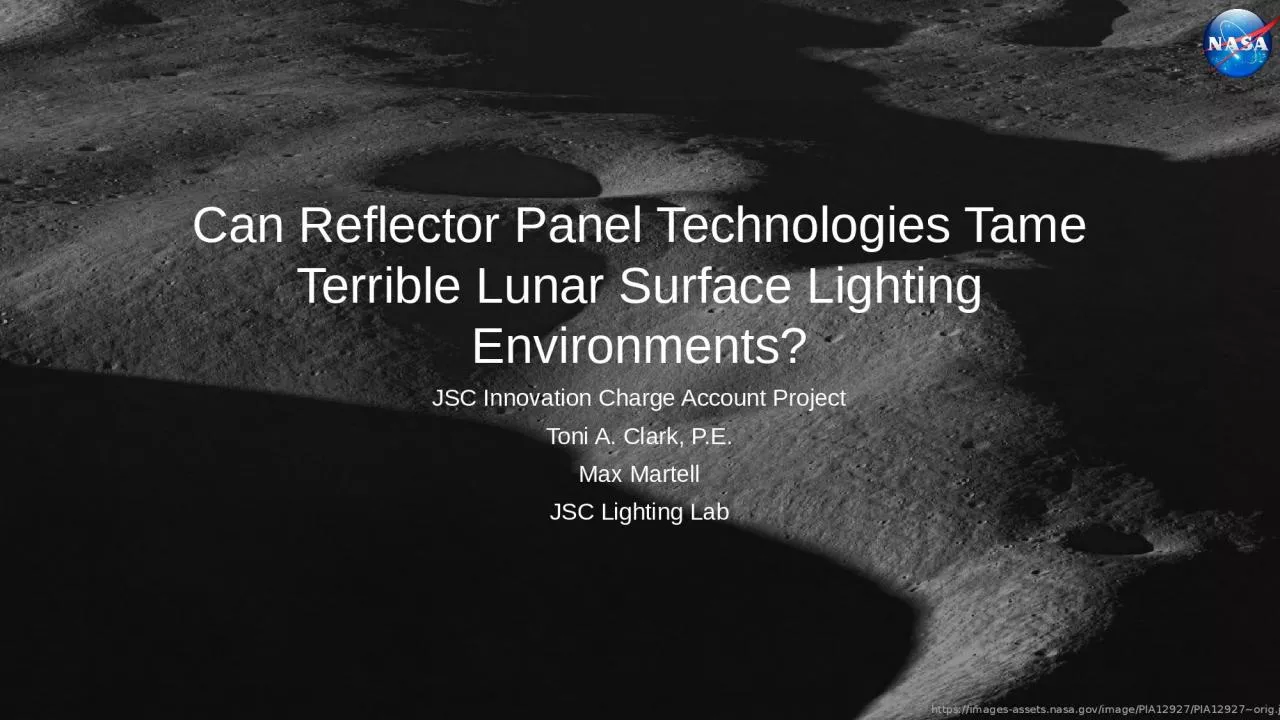
JSC Innovation Charge Account Project Toni A Clark PE Max Martell JSC Lighting Lab ICA Project Overview This project investigated passive nonpowered lighting countermeasures to improve lighting conditions where the Suns rays are nearly horizontal with the operational surface ID: 1047432

crew light lighting reflector light crew reflector lighting account charge innovation surface msc 2020 diffuser 26937 sun jsc facing

Share:

Link:

Embed:

Download Presentation from below link

Download Presentation The PPT/PDF document "Can Reflector Panel Technologies Tame Te..." is the property of its rightful owner. Permission is granted to download and print the materials on this web site for personal, non-commercial use only, and to display it on your personal computer provided you do not modify the materials and that you retain all copyright notices contained in the materials. By downloading content from our website, you accept the terms of this agreement.


Presentation Transcript

1. Can Reflector Panel Technologies Tame Terrible Lunar Surface Lighting Environments?JSC Innovation Charge Account ProjectToni A. Clark, P.E.Max MartellJSC Lighting Lab

2. ICA Project OverviewThis project investigated passive (non-powered) lighting countermeasures to improve lighting conditions where the Sun’s rays are nearly horizontal with the operational surface.NASA’s future missions are targeting the Lunar South Pole where “day” lasts for 2 weeks and the Sun is always on the horizon.The Sun’s collimated light creates harsh working conditions where the light is glaring when facing the sun, and deep long shadows are formed when turned away from the sun.The goal of this research was to determine if standard Commercial Off The Shelf (COTS) technologies, used by photographers, could increase the usability of an EVA crew member’s immediate surrounding work environment.JSC Innovation Charge Account 2020 MSC-26937-12

3. InnovationReflector panel technologies, typically used by photographers, are designed to redirect and modify light coming from a much higher intensity light source. The modified light is used to enhance the lighting for the object they are imaging. Using the orbital light source simulators at the JSC Lighting lab, and physics based optical computer models, this project investigated how different surface reflectance properties, of commercially available reflectance panels, modify worksite lighting conditions.JSC Innovation Charge Account 2020 MSC-26937-13

4. MethodsComputer ModelComputer model generated in Zemax Optics StudioModeled impacts from modification of light using diffusers and reflectorsSun’s light modeled at 5⁰ inclination angleSoftware models intensity distributionJSC Innovation Charge Account 2020 MSC-26937-14Laboratory Test4’x6’ reflector and diffuser panels1000W Plasma stage light with 10⁰ beam angle spot and inclined at 5⁰Illuminance and luminance measured at different angles with respect to the floor to document lighting modification impacts

5. Computer Model ConfigurationLunar surface modeled with Lambertian scatterTwo different “modifiers”. Translucent diffuser & semi-specular mirrorSun modeled as collimated light with 130,000 lux on targetCrewmember modeled as an opaque cylinderModel iterations:Sunlight with no modifiersReflector positioned behind crewmemberDiffuser added in front of the crew memberSide scatter added by reflector positioned to side of crew member.JSC Innovation Charge Account 2020 MSC-26937-15

6. JSC Innovation Charge Account 2020 MSC-26937-1Computer Model ResultsWithout modification, shadowing is intense.Reflector bounces light back into shadow.Addition of diffuser provides diffuse light in front of crew.Computer shows beneficial scattering from Lunar surface6Layout of Optical SystemDiffuserReflectorReflectorCrewNo CountermeasuresOne Reflector Opposite of Sun & One to sideDiffuser Added Between Crew & Sun3D Light Field Showing Effects from Reflectors & DiffuserZemax lighting simulation of direct sunlight on xEMU suit at 130,000 lux, where suit is standing on a dark Lambertian scatter type surface and lighting modifiers in use. 130K lux is on front of suit and 1k lux on back. However human vision adjusts to two orders of magnitude. Technically, the back side of the suit would appear dark.SUNSUNSUNSUNSUN

7. The horizontal and vertical detector data demonstrates how the simple placement of a diffuser in between the sun and the crew member, and addition of a reflector behind them, evens out light distribution.JSC Innovation Charge Account 2020 MSC-26937-17Horizontal work plane 1M from groundVertical Surface 1.5M from Suit Facing Away from SunBright spots are created by reflected light!Measurement Vector Normal Towards Crew Right Side & Right Angle from Sun VectorHorizontal work plane 1M from groundVertical Surface 1.5M from Suit Facing Away from SunThis shows illumination contributed from the diffuser and the reflectors!Measurement Vector Normal Towards Crew Right Side & Right Angle from Sun VectorShadow is sharp and not diffusedLighting in front of crew is harshShadow is unendingUsable horizontal surfaces surround crew Shadow is diffused

8. Laboratory Test ConfigurationPop up reflector/diffuser panels which are strategically placed:Fabric diffuser between light sensor and orbital light emulatorMetalized fabric reflector behind light sensor and orbital light emulatorMetalized fabric reflector at 45⁰ angle with respect to the light source and light sensorIlluminance/spectral irradiance sensor at different orientations:Forward facing “Sun” to represent light levels on objects in front of the crew when they are facing away from the sunReverse from facing “Sun” to represent light levels on objects in front of the crew when they are facing the sunLuminance meter to document surface brightness/luminosity of white surface object illuminated by “Sun”1000-Watt Plasma Stage lamp with 10⁰ beam angle illuminating the test rigTest conductor collecting measurements, represents crew and blocks some of the lightJSC Innovation Charge Account 2020 MSC-26937-18

9. Lighting Lab TestingJSC Innovation Charge Account 2020 MSC-26937-19Images document variety of test configurationsDiffuser Illuminance TestReflector Illuminance TestReflector Luminance TestReflector Illuminance TestReflector Luminance TestReflector Luminance TestReflector Luminance TestReflector Illuminance Test

10. ILLUMINANCELUMINANCELighting Test TerminologyWhen testing for different lighting performance metrics, it is important to understand the type of data being collected and how that impacts the required geometry for the test.Illuminance: This is the measurement of light flux impacting a surface over an area. Units are “lux” or “lumens/m2”. Illuminance is used to determine if sufficient light is impacting a surface for a human or camera to see it and resolve differences in contrast across different material surface types. An illuminance sensor is placed on and in the direction of the surface normal vector (away).Luminance: This is the measurement of light flux emitted or reflected by surface object over an area. Units are “candela/m2”. Luminance is typically used to determine visual contrast for acuity and issues with glare and potential eye hazards. A luminance measurement is directed towards the luminous or light reflecting object.JSC Innovation Charge Account 2020 MSC-26937-110MeasureLightMeasureLight

11. Lighting Lab Test ResultsJSC Innovation Charge Account 2020 MSC-26937-111123123123PanelIlluminanceLuminanceNoneFacing Up: 7350 luxTop: 2411 cd/m21. Diffuser before sensorFacing Up: 184 luxTop: 72 cd/m22. Reflector behind sensorFacing Up: 12,300 luxTop: 2178 cd/m23. Reflector @ 45⁰Facing Up: 11,800 luxTop: 2688 cd/m2PanelIlluminanceLuminanceNoneForward: 76,900 luxBehind: 66 luxForward: 27,210 cd/m2Behind: 12 cd/m21. Diffuser before sensorForward: 1930 luxBehind: 12 luxForward: 895 cd/m2Behind: 6 cd/m22. Reflector behind sensorForward: 89,000 luxBehind: 13,500 luxForward: 26,090 cd/m2Behind: 614 cd/m23. Reflector @ 45⁰Forward: 89,000 luxBehind: 76 luxForward: 26,010 cd/m2Behind: 43 cd/m2PanelIlluminanceLuminanceNoneSide: 6511 luxSide: 96 cd/m21. Diffuser before sensorSide: 64 luxSide: 21 cd/m22. Reflector behind sensorSide: 2990 luxSide: 131 cd/m23. Reflector @ 45⁰Side: 1160 luxSide: 332 cd/m2Forward  BehindLuminance values above 10,000 cd/m2 are highlighted red as a safety risk. “None” represents default state with no countermeasures.

12. ConclusionsThe quality of the work lighting conditions are significantly improved through the usage of reflectors and diffusors as compared to conditions without passive countermeasures.A pop-up diffuser placed in-between the “Sun” and the crew member scatters light, increasing the number of usable view angles to perform work by evening out illuminance levels and by reducing direct and reflected glare.A reflector placed behind or at an angle to the crew reduces shadowing by reflecting light back onto the work surfaces that were originally shadowed.The best solution would be to use a combination of diffusing material between the “Sun” and the crew member while placing a reflector directly behind or at an angle behind the crew member. The diffusor serves the purpose of removing direct glare from the sun while scattering light for observing objects directly in front of the crew while the crew is facing the sun.The diffuser makes usage of a reflector behind the crew tolerable by removing the image of the Sun from the reflector.The reflector reduces shadows created by intense directional sunlight. JSC Innovation Charge Account 2020 MSC-26937-112

13. Example of Pop-up Translucent EnclosureTest and simulation data shows the usage of simple panels are very useful for controlling light. These images demonstrate a pop-up translucent enclosure and harsh lighting conditions outside of it.Note the shadowing, contrast issues, and problems if required to work a task directly facing a bright light source.JSC Innovation Charge Account 2020 MSC-26937-113

14. Translucent Enclosure Diffuses Light in Multiple DirectionsThese images show the lighting conditions inside the pop-up translucent enclosure. The light is diffused by the first panel directly in view of the sun. Diffused light bounces around inside the enclosure, significantly muting shadows, while making it possible to work directly facing the extreme light source.A different deployment mechanism may be necessary in consideration of crew’s reduced mobility and gloved hands.JSC Innovation Charge Account 2020 MSC-26937-114

15. Application of InnovationThe COTS equipment used for this demonstration were simple popup panels, like popup panels used in car windshields to protect car interiors from heat. They were made with wire and fabric.It seems that with the simplicity of the solution, the crew could be provided with translucent fabric paneling to position, facing the Sun, in front of EVA workstations on the Moon. The translucent fabric acts as a diffuser to create a bright diffuse luminous wall, while protecting the crew from direct view of the Sun. Similarly, the crew could be provided with white opaque or metalized fabric paneling they could position opposite a “diffuser wall” to reflect light to the other side of their workstation. This solution seems portable enough that the crew could bring their own protective pop-up workspace with them, to EVA worksites established away from the safety of habitation elements. JSC Innovation Charge Account 2020 MSC-26937-115