/
P14471 Vibration Testing Apparatus II P14471 Vibration Testing Apparatus II

P14471 Vibration Testing Apparatus II - PowerPoint Presentation

olivia-moreira
olivia-moreira . @olivia-moreira
Follow
388 views
Uploaded On 2017-01-11

P14471 Vibration Testing Apparatus II - PPT Presentation

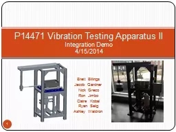
Integration Demo 4152014 Brett Billings Jacob Gardner Nick Greco Ron Jimbo Claire Kobal Ryan Selig Ashley Waldron 1 Agenda Demo Items BoM amp Budget Issues Project Plan Appendix ID: 508661

set edge easy p14471 edge set p14471 easy motor vfd number lbs rit public test follow https machine setup

Share:

Link:

Embed:

Download Presentation from below link

Download Presentation The PPT/PDF document "P14471 Vibration Testing Apparatus II" is the property of its rightful owner. Permission is granted to download and print the materials on this web site for personal, non-commercial use only, and to display it on your personal computer provided you do not modify the materials and that you retain all copyright notices contained in the materials. By downloading content from our website, you accept the terms of this agreement.


Presentation Transcript

Slide1

P14471 Vibration Testing Apparatus IIIntegration Demo4/15/2014

Brett BillingsJacob Gardner Nick Greco Ron JimboClaire KobalRyan SeligAshley Waldron

1Slide2

AgendaDemo Items

BoM & BudgetIssuesProject PlanAppendix2Slide3

Demo Items3

Mount 18 lb luminaire to 3/4'' conduitAdjust displacementTurn on VFD & motor, 500 RPMDisplay RPM & elapsed time on LCDEnd with E-StopSlide4

BoM / Budget4

Current costs:Remaining costs:VFD enclosure - $80Shipping to Syracuse - $600Travel Expenses - $240Expected final cost: $3,400https://edge.rit.edu/edge/P14471/public/WorkingDocuments/Detailed%20Design/BOM_rev6_tracking.pdfSlide5

Issues5

Reinforce motor mountVibration noise at certain frequencies

Decide on Control Panel layout

Shipping apparatus to Syracuse

RyanSlide6

Project Plan6Slide7

Questions?7Slide8

Appendix

8Slide9

Room Layout9Slide10

Selected Design

Interchangeable ConduitsMotor with V-beltVFDDigital Dial GaugeEncoderLCD, MicrocontrollerPolycarbonate GuardsE-stopPaint for Rust Protection10Slide11

11Slide12

Engineering Requirements

Number

Requirement

Raw Score

Units

Ideal Measure

1

Displacement of luminaire

69

in

1/32

2

Vibration of luminaire

69

cycles/min

2000

3

Duration of vibration test

69

hours

35

4

Isolate motor from oil spills

45

Binary

Yes

5

Maintenance Documentation

44

Survey (easy

to follow)

80%

6

Mount pendant configuration

35

Binary

Yes

7

Operation Documentation

33

Survey (easy

to follow)

80%

8

Machine won't operate if crankshaft enclosure is open

25

Binary

Yes

9Completely stop machine with Emergency Stop25seconds< 1010Maximum voltage of Motor25V AC24011Minimize number of operators21people212Max weight of mounted luminaire20lbs> 15013Visually display settings and status of test18BinaryYes14Steps to set up16steps< 1015Setup Time16seconds< 12016Low Sound15dBA< 85 17Minimize pinch points15Count< 318Total materials cost15$< 4,00019Mount stanchion configuration7BinaryYes20Mount yoke configuration7BinaryYes21Mount trunnion configuration7BinaryYes22Machine footprint5in2< 34X48

12Slide13

House of Quality

Engineering

Metrics 

Customer Requirements

Customer Weights

Displacement of luminaire

Vibration of luminaire

Duration of vibration test

Low sound

Machine won't operate if moving parts are exposed

Completely stop machine with Emergency Stop

Minimize pinch points

Minimize number of operators

Voltage of motor

Mount pendant configuration

Mount stanchion configuration

Mount yoke configuration

Mount trunnion configuration

Visually display settings and status of test

Operation documentation

Steps required for Set-up

Isolate motor from oil spills

Maintenance documentation

Max weight of mounted luminaire

Total materials cost

Time to Set up

Machine footprint

Adherence

to UL844 testing standard

5

5

5

5


    Apparatus is safe5   3553       3  1    Motor must be compatible with available voltage5        5       33    Ability to test multiple configurations3555      5111         Easy to use3       5     133 1  3 Easy to maintain2       3      1 53    Visually display test information/feedback to operator3333          511 1  1 Ability to test a range of luminaire weights4555      5111     5   Cost under $40003                   5  Long service life4              1153  1 Similar dimensions to existing machine1                     5Technical Targets (Specifications) 1/32 in.2000 cycles/min35 hours< 85 dBAyes< 10 seconds< 3≤ 2< 240 V ACYesYesYesYesYes80% via survey (easy to follow)< 10 stepsYes80% via survey (easy to follow)> 150 lbs< $4000< 120 seconds< 34X48 in2Raw score6969691525251521253577718331645442015165Relative Weight11%11%11%2%4%4%2%3%4%6%1%1%1%

3%

5%

3%7%7%3%2%3%1%

13Slide14

Safety ChecklistER # 8 – Machine Guarding

ER # 9 – Emergency StopER # 16 – Low Sound

14Slide15

Test Plans15

Refer to Excel documenthttps://edge.rit.edu/edge/P14471/public/WorkingDocuments/MSDII_Build%20Test%20Documentation/P14471 Test Plans_Rev2.xlsxor EDGEhttps://edge.rit.edu/edge/P14471/public/Build%2C%20Test%2C%20DocumentSlide16

Maintaining Displacement

ER #1: Displacement must be 1/32’’Clamping force:Provided by 2 x A574 screws - 5/8’’-11 M = torque on screws= 168.9 M ft-1

Frictional force:2 possible locations:= 33.8 M ft-1

(worst case)Maximum force applied:1.68 ft-lbs. (motor) at 1/32’’= 645 lbs.Required screw torque:= 38 ft-lbs. (Safety factor of 2)Max recommended A574 torque = 220 ft-lbs*Detailed calculations in Appendix

1

2

16Slide17

Bolt TorqueGuide

17Slide18

Setup ImprovementsER # 11 – Minimize number of operators

ER # 14 – Steps to set upER # 15 – Setup time18Slide19

Setup Improvements

Finer set screwBefore:11 threads per inch1 turn = 290% of displacement!After:100 threads per inch1 turn = 33% of displacementChanges required:Machine new set screw plateRequires threaded bushing for set screw

19Slide20

Set Up Improvements

Set screwAccount for excess space between conduit and collarFlange Dimensioned to be placed in same location every timeBlocks on the C

channel

Flange

Collar – crankshaft connection

Collar – set screws

ER # 11 – Minimize number of operators

ER # 6, 19-21 – Mount 4 configuration types

ER # 13, 14 – Setup time, number of steps

20Slide21

Full Risk Analysis21

See EDGEhttps://edge.rit.edu/edge/P14471/public/ProjectManagement/Risk%20Analysis.pdfSlide22

VFD Damage Incident22

See EDGEhttps://edge.rit.edu/edge/P14471/public/WorkingDocuments/VFD%20Damage%20Incident/VFD%20Damage%20Incident.pdf