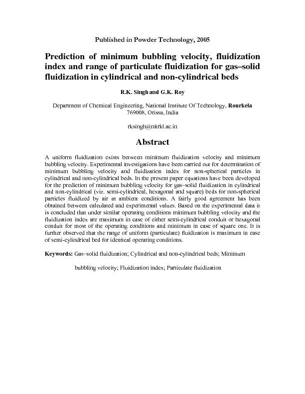
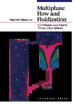
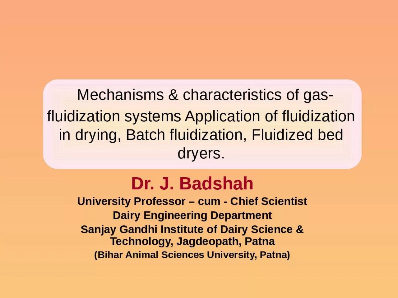
Dr J Badshah University Professor cum Chief Scientist Dairy Engineering Department Sanjay Gandhi Institute of Dairy Science amp Technology Jagdeopath Patna Bihar Animal Sciences University Patna ID: 928390
Download Presentation The PPT/PDF document "Mechanisms & characteristics of gas-..." is the property of its rightful owner. Permission is granted to download and print the materials on this web site for personal, non-commercial use only, and to display it on your personal computer provided you do not modify the materials and that you retain all copyright notices contained in the materials. By downloading content from our website, you accept the terms of this agreement.
Slide1
Mechanisms & characteristics of gas-fluidization systems Application of fluidization in drying, Batch fluidization, Fluidized bed dryers.
Dr. J. Badshah
University Professor – cum - Chief Scientist
Dairy Engineering Department
Sanjay Gandhi Institute of Dairy Science & Technology,
Jagdeopath
, Patna
(Bihar Animal Sciences University, Patna)
Slide2Solid Gas Separation in spray DryersImportance of Separation of fine powder particles (10 -30%) from air exiting from drying chamber
Economic ReasonsPollution Problems Methods of powder recovery from exhaust air 1. Cyclone separators2. Bag filters3. Wet scrubbers
Working of Cyclone Separators
High efficiency, Easy to maintain and Easy to clean.
Vortex motion due to centrifugal force move the particles of powder towards the wall but the Drag force of the air tries to carry the particles towards axis of cyclone.
Centrifugal force predominant over drag force resulted in separation of particles towards radial direction. Powder leaves the bottom of the cyclone via a locking device. The clean air spirals upwards along the center axis of the cyclone and passes out at the top.
Slide3Efficiency of Cyclone separators
Optimum size and Nos. of cyclone depend upon:Centrifugal Force = m ( vt ) 2/ r
Higher mass, Higher tangential velocity and lower radial distance of particles i.e. conical shape towards exit of powder particles results in high efficiency of separation.
Residence time should be equal to the time required by the travel towards wall for smallest size of particles
Risk of air leaks through valves in multi-cyclones
Need of one valve , final cyclone and central hopper
Same pressure drop over each cyclone to avoid powder losses
Cleaning problems and large nos. of corners and crevices for bacterial growing and multiplying problem
Optimum size is not 1.0 meter dia. Of cyclone but generally 2.5 -3.0 m dia. With air handling cap. Of 25,000 to 30,000 kg/hr.
Slide4Efficiency of Cyclone separatorsCyclone diameter : Inlet duct diameter = 3:1
Cyclone diameter : exit duct diameter = 10:1Air through-put velocity V0 and increased pressure drops will also increase the efficiency, but the energy requirement will increase simultaneously.In general the upper limit of pressure drop is 175-200 mm WG for
skimmilk
powder and 140-160 mm WG is the maximum for whole milk in order to avoid deposits and final blocking.
In most cases rotary valves are used as air lock and product discharge at the bottom of the cyclone
Slide5Terms to define efficiency of cycloneThe critical particle diameter : The particle size that will be completely removed from the air flow (100% collection efficiency).
The cut size : The size for which 50% collection is obtainedThe overall cyclone efficiency : It is obtained when handling a product of definite size distribution.
Another method of learning the cyclone efficiency is by a simple powder loss measurement after the cyclone.
A very small fraction of the out-going air is passed through a high-efficient mini cyclone or through micro dust filters.
Slide6Bag FiltersStack Losses Requirement: Less than 0.5 % to make
ecofriendlyBag Filters of proper fabrics material may give high efficiency with collection of particles of 1 micron size even. Fabrics filters consist of woven fabrics of tubular shape and supported over certain frames preferable.Arrangement of multi bag filters to have equal volume of air through each filter from outside to insideClean air is exhausted from inner part of bags to exhaust manifolds and powder
The collected powder is automatically shaken off by blowing compressed air through the filter bags from the inner side. The powder is collected at the bottom via a rotary valve.
Continuous build up dust layer on the fabric surface results in increase in pressure drop and thus in drop of capacity.
To avoid this, the dust is continuously dislodged by mechanical sacking or by reverse air pulsations.
Slide7Bag Filters.. Contd.Collection efficiency : 99 % for particles upto
1 micronPressure Drop : 7- 15 cm of water gaugeDry Recovery is advantageous in comparison to wet scrubbersNo corrosion and rustingPlugging of fabric pores need maintenance and frequent replacement due to hygrscopicity of powderThe amount of powder collected is directly proportional to the powder loss, which will mainly due to:
• Feed with low solids or feed containing air
• High outlet air temperature
• Low particle density due to entrapment of air
• Leaking product outlet from old non-adjusted rotary valves
• Blocked cyclone
• Change in drying parameter resulting in decrease of mean particle size
Slide8Wet Scrubbers Working of wet – scrubber:
It is based on the venturi scrubber principle with an efficiency very close to 100%. The liquid is injected through full - cone nozzles in the ventury as driving fluid and the outlet air from the spray dryer containing powder particles is accelerated to a high velocity in the venturi inlet before mixing zone. Due to different velocities between the air/particles and the liquid droplets, they will collide, mixed and the powder will dissolve in the liquid droplets.
Passing through the subsequent diffuser this process will continue simultaneously with a certain pressure recovery of the air/droplet mix.
Passing through the separator, air and liquid are separated again. The air leaves through the centre duct and the liquid through the bottom outlet for further processing or recycling depending on what system is selected.
Slide9Wet ScrubbersProduct is collected wet which subsequent drying.
Initial Cost is high.Pressure drop is higher. Thus operating cost is more.Large space requirement.Sever corrosion and maintenance problem.
Slide10Schematic diagram of Wet scrubbers
Slide11Bag Filter in Niro spray Dryers
All the process air is discharged through bag filters integrated inside the drying chamber at the periphery, where they hang down from the ceiling. The separation efficiency (≤10 mg/Nm3 air) ) is the same as that known from the Niro SANICIP™ CIP‐able bag filter.During operation the product, which is collected on the outside of the filter material, is removed by a compressed air stream blown into the inside of each bag by means of a specially designed reverse jet air nozzle (patented) positioned above each bag.
This results in a low pressure drop across the filter, i.e. reduced energy consumption and noise emission.
Another
special feature (patented) in the IFDTM plant ‐ inherited from the
Niro
SANICIP™ bag filter ‐ is the wet cleaning of the bags from inside towards the dirty outside by means of CIP solution, which reduces the overall CIP liquid amount and thereby the effluent from the plant.
Slide12THANK YOU