/
Medical imaging with a photogate: an activity for high school and college students Medical imaging with a photogate: an activity for high school and college students

Medical imaging with a photogate: an activity for high school and college students - PowerPoint Presentation

paisley
paisley . @paisley
Follow
342 views
Uploaded On 2022-05-18

Medical imaging with a photogate: an activity for high school and college students - PPT Presentation

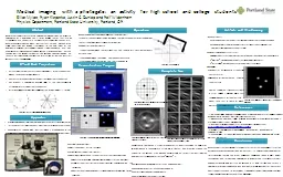
Elliot Mylott Ryan Klepetka Justin C Dunlap and Ralf Widenhorn Physics Department Portland State University Portland OR We present a laboratory activity in computed tomography CT primarily composed of a photogate and a rotary motion sensor that can be assembled quickly and partially automa ID: 911944

data figure light photogate figure data photogate light image scan physics cylinders reconstruction enclosure line projection medical apparatus artifacts

Share:

Link:

Embed:

Download Presentation from below link

Download Presentation The PPT/PDF document "Medical imaging with a photogate: an act..." is the property of its rightful owner. Permission is granted to download and print the materials on this web site for personal, non-commercial use only, and to display it on your personal computer provided you do not modify the materials and that you retain all copyright notices contained in the materials. By downloading content from our website, you accept the terms of this agreement.


Presentation Transcript

Slide1

Medical imaging with a photogate: an activity for high school and college students

Elliot Mylott, Ryan Klepetka, Justin C. Dunlap and Ralf WidenhornPhysics Department, Portland State University, Portland, OR

We present a laboratory activity in computed tomography (CT) primarily composed of a photogate and a rotary motion sensor that can be assembled quickly and partially automates data collection and analysis. We use an enclosure made with a light filter that is largely opaque in the visible spectrum but mostly transparent to the near IR light of the photogate (880nm) to scan objects hidden from the human eye. This experiment effectively conveys how an image is formed during a CT scan and highlights the important physical and imaging concepts behind CT such as electromagnetic radiation, the interaction of light and matter, image artifacts and windowing.

[1] Buzug T M 2008

Computed Tomography: From Photon Statistics to Modern Cone-Beam CT

(Berlin: Springer) pp 2, 201, 207, 485, 85,437

[2] Delaney C and Rodriguez J 2002 A simple medical physics experiment based on a laser pointer

Am.J. Phys. 70 1068-70[3] Murphy, S 2010 Basic Apparatus for CT Analogy, 2010 March 5, http://web.phys.ksu.edu/mmmm/instructor/.[4] Wolbarst, AB 2005 Physics of Radiology (Madison, WI: Medical Physics Publishing) p 409[5] Kane SA 2003 Introduction to Physics in Modern Medicine (Abingdon, UK: Taylor & Francis) pp 189-195

Abstract

References

CT and Back Projection

Apparatus

Principal components were Vernier photogate and rotary motion sensor

Instead of X-rays, we used a near IR light source to simulate a CT scanner

The enclosure is a Congo Blue light filter, which is largely opaque in the visible spectrum but mostly transparent to the near IR photogate light.

Operation

X-rays from the source are attenuated by objects in the scanned area, which is recorded as projection data That data is spread back onto a reconstruction of the scanned area This process is completed multiple times as the source/detector assembly rotates about the scanned areaAfter multiple back projections an image of the original object(s) forms.

Conclusion

We have constructed a simple, safe apparatus that effectively demonstrates the basic mechanism and concepts behind CT scans. It is comprised of a photogate, rotary motion sensor, and other equipment commonly found in most physics teaching labs. The setup can be completed in minutes and scan times are short enough that multiple objects can be imaged in a single session. The activity is appropriate for high school and college level physics or biology courses. This activity gives students a chance to learn about trigonometry, electromagnetic radiation, radiographic imaging, image analysis and windowing.

When the photogate becomes blocked, the program…calculates the equation of the line between the source and detector of the photogate enters the projection data along that original line The inputs of the program are the distance between the rotational axis and the origin, also called the focus-center distance (FCD) the angle between the FCD line and the negative x-axis q the angle between the FCD line and the scanning line f

Artifacts and Windowing

Figure 1.

Basic reconstruction technique of CT

The LabVIEW program…Collects and displays data in real timeForms image step by step (figure 7). Comes with a simulated CT scanner that uses the same algorithmQuick scans of multiple combinations of object sizes and positions. Explores the effects of the three parameters (FCD, f and q) on the final imageAn effective graphical demonstration of how back projection forms an image.

Image artifacts:Caused by either the reconstruction algorithm or the scanning technique Can be incorporated into the laboratory session as they are important considerations in medical scanners as wellThe most common artifacts are… Unwanted data that does not correlate to either the cylinders or the enclosure“Blurring” (amplitude on reconstruction proportional to 1/r)“Afterglow” (misplaced data caused by short scan times)

Figure 2.

CT apparatus and light filter

Complete Scan

Figure 3. CT geometry

Figure 5. Positions of three cylinders in the enclosure (0.6 cm in diameter)

Figure 6. Final image of cylinders in figure 4 (36 scans, 20 min scan time)

Figure 7. Scans of the cylinders as shown in figure 5 taken in 10o increments over q =150o

Reconstruction Program

Figure 4. LabVIEW user interfaces (manual and simulated)

The images in figure 6 and 7 are of three identical cylinders, each with a diameter of 0.6 cm, placed in the enclosure as shown in figure 5. The large ring around the cylinders in the images is the opaque enclosure which reflects the light from the photogate at shallow angles effectively “blocking” it.

The time needed to complete a full scan is dependent on…

The number of passes (each having a unique q) The rotational speed of the photogate The resolution of the reconstruction.

Figure 8. The same data from figure 6 after applying a window.

WindowingEmphasizes differences in attenuation characteristicsDone by adjusting the relative values of the gray scale Figure 8 shows the same data as figure 6 after applying a window. Note that the lower boundary of the grey scale is higher than that in figure 6, which obscures the unwanted data.