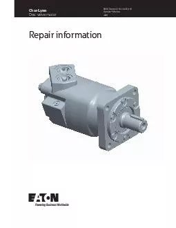
/
July  CharLynn Disc Valve Motor  Series includes Big  Geroler  dna  srotoM Repair Information July  CharLynn Disc Valve Motor  Series includes Big  Geroler  dna  srotoM Repair Information

July CharLynn Disc Valve Motor Series includes Big Geroler dna srotoM Repair Information - PDF document

pamella-moone
pamella-moone . @pamella-moone
Follow
614 views
Uploaded On 2015-03-04

July CharLynn Disc Valve Motor Series includes Big Geroler dna srotoM Repair Information - PPT Presentation

Tapered Key Shaft and Bearing Kit 112 inch Straight Shaft and Bearing Kit 112 inch 17 Tooth Splined Plug Assembly Plug Assembly Plug Assembly Check Valve Plug Assembly Ball Plug Key Dust Seal Optional Seal Guard Retainer 006 Retainer 006 Spring brPa ID: 41068

Tapered Key Shaft and

Share:

Link:

Embed:

Download Presentation from below link

Download Pdf The PPT/PDF document "July CharLynn Disc Valve Motor Series ..." is the property of its rightful owner. Permission is granted to download and print the materials on this web site for personal, non-commercial use only, and to display it on your personal computer provided you do not modify the materials and that you retain all copyright notices contained in the materials. By downloading content from our website, you accept the terms of this agreement.


Presentation Transcript

Repair informationChar-LynnDisc valve motor 6000 Series (includes Big 6)-006 2 Char-Lynn Current production -006 Version 3 Parts drawing RetainerOptionalSeal GuardSealSealSealPlugSleeve, Dash PotValve housing(Split ange ports)Piston ShuttleSleeve, Dash PotPlug assemblyPlug AssemblyPlug AssemblySpringSpringPoppetGerolerGerolerShuttle (Two way) RetainerDust SealShaft face sealO-ringPlugassemblyValve housingSealSealSealBallSealSealDriveKeyGerolerValveValveValveSealBoltSpringSpringInnerHousing, BearingKeySealShaft sealBack-upScrew, CapDust sealRetainer, FrontShaft andBearinglessBearingShuttle valvelocation whenCheckvalveOuterBalanceShaft and(1-1/2 inch straight)Shaft and(1-1/2 inch 4 Tools Shaft face sealDust sealShaft seal Special global mountShaft and bearing assembly Seal Retainer, FrontScrew, Cap 9,52 [.375]Grind at spots on each sideApprox. 12,7 [.50]215,9 [8.50](273,05 [10.75] required for 985 cm3/r [60.0 in3/r] Displ.)Alignment studs (2)25,4 [1.00]1/2-20 UNF thread12,7 [.50] Dia. Steel Rod Wheel motor and bearingless motor repair information on page 11,12. Shuttle valve and seal guard repair information on page 13. Seal guard reference on page 13.Tools required for disassembly and reassemblyTorque wrench (90 Nm [800 lb-in] capacity)305 to 406 mm [12 to 16 inch] breaker bar3/4 inch and 1/2 inch socketsSmall screwdriver (150 to 200 mm [6 to 8 inch] long,6 mm [1/4 inch] blade)3/16 inch Hex KeyHydraulic press — 1335 N [300 lbf]Plastic or rubber hammer*Bullet (600464) for 1-1/2 inch diameter shafts*Available by special order through our service department. 5 Cleanliness is extremely important when repairing a hydraulic motor. Work in a clean area. Before disconnecting the lines, clean port area of motor thoroughly. Use a wire brush to remove foreign material and debris from exterior joints of motor. Check shaft and keyway, use 600 grit paper/cloth to remove all nicks, burrs, and sharp edges that might damage the shaft seals when installing retainer on shaft and bearing assembly. Before starting disassembly procedures, drain oil from inside of motor. Place motor in a vise with output shaft down. Clamp Figure 1). Excessive clamping pressure on housing will cause distortion. When clamping, use some protective device on vise, such as special soft jaws, we recommend that you keep the motor in the vise during disassembly. Follow the clamping procedures Remove 4 bolts (or nuts for earlier models) from motor. Remove studs (earlier models) as shown in step 16. Lift valve housing straight up. If done carefully, the valve for easy removal. PlugassemblyValvehousingCheck plugassemblySeal Carefully remove the following from the valve 1 seal, 92,3 mm [3.63 inch] I.D.1 seal, 7,6 mm [.30 inch] I.D.2 check valve plug assemblies (plug, seal, spring, Innerface Spring (3)ValveOuterBalance ring Remove 3 balance ring springs.Remove balance ring subassembly.Remove inner and outer face seals from the balance Lift off valve. Valve plateSealValve drive Remove valve plate.10.Remove 95,0 mm [3.74 inch] I.D. seal from valve plate 6 11.Remove valve drive (see Figure 5). SealSealDriveGeroler 12.Remove Geroler. Retain rollers in outer Geroler ring 13.Remove 2 seals (6,1mm [.24 inch]) from Geroler, 1 seal on each side of Geroler.14.Remove drive.15.Remove 95,0 mm [3.74 inch] I.D. seal from bearing 16.Use a stud remover or vise grips to remove studs (earlier models only). Then clamp bearing housing in vise as shown in Figure 7. Loosen 6 bolts. Then remove bolts and retainer. You may have to pry retainer free but do not damage housing or retainer. Figure 7 Figure 8 RetainerDust sealSeal ShaftsealBack-up 17.Remove 92,3 mm [3.64 inch] I.D. seal, shaft seal and back-up ring (if supplied) from retainer. Use a small screwdriver to remove dust seal. Do not damage bore of retainer. Shaft face sealShaft andbearing Bearing Figure 1018.Remove shaft and bearing assembly. You may need a press to remove shaft and bearing assembly(see Figure 10)19.Remove shaft face seal from bore of bearing housing (see Figure 10). Do not damage bore of bearing ote:Individual parts of the shaft and bearing assembly are 7 Check all mating surfaces. Replace any parts that have scratches or burrs that couId cause leakage. Clean all metal parts in clean solvent. Blow dry with air. Do not matter could get into the hydraulic system and cause damage. Do not use a coarse grit papers/cloth or try to file or grind motor parts. Check around the keyway and chamfered area of the shaft for burrs, nicks, or sharp the retainer.ote:Lubricate all seals (prior to installation) with petroleum jelly such as Vaseline. Use new seals when reassembling the motor. Refer to parts list (6-159 6000 Series - 006) for replacement parts and proper kit number. Shaftface BearingSealseat Figure 11Apply petroleum jelly to shaft face seal. Install seal in seal seat. Seat seal properly in groove (see Figure 11 and 14). A damaged or improperly installed shaft face seal parts wear. BearinghousingShaft and Figure 1221.Install shaft and bearing assembly in bearing housing (see Figure 12). Do not damage seal in bore of housing. You may need a press to install shaft and bearing assembly. RetainerDust SealSealShaftsealBack-up Figure 13retainer. Metal side of dust seal must face toward retainer as shown in Figure 14. If a press isn’t Dust Seal Lip RetainerBack-upringBearingShaft andShaftShaftSeal Figure 14Install 92,3 [3.64] I.D. seal, back-up ring and shaft seal in retainer. Flat or smooth side of shaft seal must face toward retainer as shown in Figure 14. Apply petroleum jelly to inside diameter of shaft seal(after installing seal).Before installing retainer, place a protective sleeve of bullet (see note below) over shaft. Grease inside diameter of dust and shaft seals. To prevent damage to seals, install retainer over shaft with a twisting motion. Do not cut or distort shaft seal. Damage to shaft seal will cause external leakage.ote:Bullet 600464 for 1-1/2 inch diameter shafts available—by special order through our service 8 164 2 53 Figure 15Install and finger tighten all 6 bolts. Torque bolts to 6 Nm [50 lb-in] in sequence (see Figure 15). Then final torque to 34 Nm [300 lb-in], in sequence.ote:Full torque 34 Nm [300 lb-in] on one bolt at a time can damage bolt or retainer. Seal Figure 16Reposition motor in vise with output shaft down. Figure 16.27.Pour a small amount of light oil inside the output shaft.in bolt holes of bearing housing (see Figure 16). If ment purposes when stacking parts.Apply a light film of petroleum jelly on 95,0 mm [3.74 inch] I.D. seal. Install seal in bearing housing (see Figure 16).Install drive in output shaft (insert longer splined end of drive first), (see parts drawing on page 3).31.Apply petroleum jelly on 2 seals, 6,1 mm [.24 inch] I.D. Install seals (1 on each side of Geroler) in case drain grooves of Geroler.ote:Installation at this point involves 3 steps in timing the motor. Timing determines the direction of rotation of the output shaft.Timing parts include:1. Geroler2. Valve drive3. Valve Plate4. Valve ValveplateAlignmentGerolerRotate valve clockwise Largest open pocketAnyone of 6 portsPressureCase drainNote: Case drain holes (2) Valve Figure 17 Timing alignmentTiming Step No. 1 — Locate largest open pocket in Geroler. Then mark location of pocket on outside edge of Geroler (see Figure 17).housing (see Figure 17). Retain rollers in outer Install valve drive in Geroler.Apply a light film of petroleum jelly on 95,0 mm [3.74 inch] I.D. seal. Install seal in valve plate.hole in Geroler. Install valve plate (seal side toward Geroler) on Geroler as shown in Figure 17.Timing Step No. 2 — Locate slot opening in valve plate which is in line with largest open pocket of Geroler (see Figure 17). 9 Timing Step No. 3 — Locate any one of the side openslot of valve plate that is in line with largest open pocket of Geroler. Rotate valve clockwise (1/2 spIine tooth) to engage valve with the valve drive spline, alignment reference shown in Figure 17 (above). This procedure provides standard timing when pressurized as shown in Figure 18 (below). ClockwiserotationTimingStandardPressure inPressure in Figure 1837.face of valve housing (see Fig. 19). SealCase DrainSealValve housingBalance Ring Spring (3) Figure 19Apply a light film of petroleum jelly on 7,6 mm [.30 inch] I.D. seal. Install seal in case drain groove of ve of inch] I.D. seal. Install seal in outside seal groove of Install face seals in the positions shown in Figure 20 or the motor will not operate properly. Do not force or bend these face seals. Any damage to these seals will affect the operation of the motor. 41.Insert your finger through port of housing. Apply pressure to side of balance ring assembly. Hold ring 21). Align case drain hole in housing with case drain hole in valve plate. Install valve housing against ote:After installing valve housing on valve plate, check between body parts of motor for unseated seals. BoltCheckplugPlug Figure 23 Balance ring Inner seal Pin Outer seal 10 models) opposite alignment studs. Remove align4 nuts for earlier models). Torque bolts (or nuts) to 98 Nm [864 lb-in/ 72 lb-ft], in sequence (see Figure 24). Drain plug torque to17 Nm [150 lb-in]Check plug torque to7-14 Nm [60-120 lb-in] 143 C h a r - L y n n Hydraulics Div.Eden Prairie, MN 55344 Install 2 check plug assemblies (ball, spring, plug with seal). Also install case drain plug with seal, parts 11 A different bearing housing is used on standard motor and the same disassembly and reassembly procedures apply.al guardAfter completing assembly of the shaft and bearing assembly into the bearing housing, press the Extreme Duty Seal Guard onto the shaft with a tool that will provide an even push over the seal. This tool must bottom out against the front retainer and provide a 4.9 mm [.19 inch] stop for the extreme duty seal guard. (Applicable for standard and wheel motors) Bearing housingBoltKeySealRetainerNutDust sealBack-up ring(if supplied)Shaft seal 4.9 [.19]MAX Bearing housingFront retainerExtremeduty Figure 25Figure 26Figure 27 12 This motor is the same as the standard without the shaft/bearing assembly, bearing housing and retainer. The mounting Figure 28). Follow same disassembly and standard motor. Loctite information for bearingless motor below. This motor requires Loctite in Follow these procedures:Adequate Loctite penetration and sealing depend highly on cleanliness and dryness solvent to clean excess oil from threads of flange after disassembly. You may need to use a tap to clean threads of excess old Loctite. Then, after you have fully reassembled the motor, apply 2 to 3 drops of Loctite no. 290 at top of threaded holes ote:Allow Loctite 5 minutes for thread penetration before installing motor Mountingange DriveSealSeal Attention: Figure 28Figure 29 13 Motors with shuttle and, or seal guard PistonPoppet*Plug/O-ring S/A must be removed anddrain line added for shuttle valve operation.SpringSpringPoppet Seal Guard Add-on Option DashpotOptionalPlug/O-ring*S/A (9/16-18)Torque to23 Nm [200 lb-in]Thread)Plug/OringEnlargedPlug/O-ringDashPlug/O-ringTorque to5 Nm [50 lb-in](LubricatedThread) For More Detailed Information Contact Eaton Corp. HydraulicsDivision 15151 Highway 5 Eden Prairie, MN 55344.Specications and performance data, Catalog No. 11-878 Each order must include the following:How to order replacement parts1. Product number3. Part name4. Part number5. Quantity of Parts C h a r - L y n n ®Product numberEaton Corp. Hydraulics Div.Eden Prairie, MN 55344 Product Number000 0000 000 Date codeWeek ofYear 01Product lineProductNumberLastNu,bers (S)00 00 Engineering 14 Product numbers—6000 Series motors Use digit prefix —112-, 113-, or 114- plus four digit number from charts for complete product number—Example 114-1047.Displacement cm/r [ in/r ] and Product NumberMountingShaftPorts195[11.9]245[ 15.0]310[19.0]390[23.9]490[30.0]625[38.0]985[60.0]Standard1-1/2 inch Straight1-5/16 O-ring112-1064-1065-1066-1067-1068-1107-106940 mm StraightG 1 (BSP)112-1094-1095-1096-1097-1098-10991-1/2 Inch17 T Splined1-5/16 O-ring112-1058-1059-1060-1061-1062-1109-1063G 1 (BSP)112-1088-1089-1090-1091-1092-1093WheelMotor40 mm StraightG 1 (BSP)113-1082-1083-1084-1085-1086-1100-10871-3/4 Inch Tapered1-5/16 O-ring113-1070-1071-1072-1073-1074-1093-1075Bearingless1-5/16 O-ring114-1031-1032-1033-1034-1035-1055-1036G 1 (BSP)114-1043-1044-1045-1046-1047-1048114-1047 112-1215 Use digit prefix —112- plus four digit number from charts for completeproduct number—Example 112-1215.Orders will not be accepted without three digit prefix.Displacement cm/r [ in/r ] and Product NumberMountingShaftPorts310[19.0]390[23.9]490[30.0]625[38.0]737[45.0]800[49.0]985[60.0]Standard50 mm StraightG 1 (BSP)112-1217-1218-1215-1216-1247-1219-1220 15 Ea1000 Eaton BoulevardCleveland, OH 44122United States© 2019 EatonAll Rights ReservedPrinted in USADocument No. C-MOLO-TS009-E1 toFluid Power GroupHydraulics Business USA14615 Lone Oak RoadEden Prairie, MN 55344USATel: 952-937-9800Fax: 952-294-7722www.eaton.com/hydraulicstoFluid Power GroupHydraulics Business EuropeRoute de la Longeraie 71110 MorgesSwitzerlandTel: +41 (0) 21 811 4600Fax: +41 (0) 21 811 4601toFluid Power GroupHydraulics Business Asia Pacic11th Floor Hong Kong New World Tower300 Huaihai Zhong RoadShanghai 200021Tel: 86-21-6387-9988Fax: 86-21-6335-3912 Eaton is a registered trademark.All trademarks are property of their respective owners. 6000 Series Char-Lynn Motors6000 SERIES CHAR-LYNN MOTORS C-MOLO-TS009-E1 October 2019 www.eaton.com 6000 Series Char-Lynn Motors6000 SERIES CHAR-LYNN MOTORS C-MOLO-TS009-E1 October 2019 www.eaton.com