/
Owners manual  Installation manual  All Rights Reserve Owners manual  Installation manual  All Rights Reserve

Owners manual Installation manual All Rights Reserve - PDF document

pasty-toler
pasty-toler . @pasty-toler
Follow
516 views
Uploaded On 2015-05-15

Owners manual Installation manual All Rights Reserve - PPT Presentation

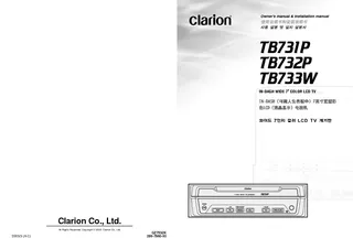
Copyright 57513 2003 Clarion Co Ltd 20033 A57527C QZ7532K 280796000 Clarion Co Ltd INDASH WIDE 7 COLOR LCD TV 1287935403605435516761552661 1287935403605435516761552661 1287935403605435516761552661 12879354036054355 ID: 67433

Copyright 57513 2003 Clarion

Share:

Link:

Embed:

Download Presentation from below link

Download Pdf The PPT/PDF document "Owners manual Installation manual All ..." is the property of its rightful owner. Permission is granted to download and print the materials on this web site for personal, non-commercial use only, and to display it on your personal computer provided you do not modify the materials and that you retain all copyright notices contained in the materials. By downloading content from our website, you accept the terms of this agreement.


Presentation Transcript

Owner’s manual & Installation manual All Rights Reserved. Copyright © 2003: Clarion Co., Ltd.2003/3 (AáC)QZ7532K280-7960-00 ৬੉٘ੋ஖ஸ۞-$%57҅ӝ߈ 2TB731P/TB732P/TB733W OwnerÕs manual Please read this OwnerÕs manual & Installation manual in its entirety before proceeding with wire OwnerÕs manual1.FEATURES.........32.PRECAUTIONS..43.CONTROLS........54.BUTTON TERMINOLOGY................................................................................................................65.CAUTIONS ON HANDLING..............................................................................................................7Concerning the LCD screen...............................................................................................................7Cleaning.............................................................................................................................................7Concerning the wide screen..............................................................................................................76.REMOTE CONTROL.........................................................................................................................87.OPERATION.....10Basic Operations..............................................................................................................................10TV Mode Operations........................................................................................................................138.TROUBLESHOOTING....................................................................................................................179.SPECIFICATIONS...........................................................................................................................19 Installation and Wire connection manual1.BEFORE STARTING.......................................................................................................................212.PACKAGE CONTENTS..................................................................................................................213.GENERAL CAUTIONS....................................................................................................................214.CAUTIONS ON INSTALLATION.....................................................................................................225.INSTALLING THE MAIN UNIT........................................................................................................236.REMOVING THE MAIN UNIT..........................................................................................................257.CAUTIONS ON WIRING.................................................................................................................258.WIRE CONNECTIONS....................................................................................................................269.SAMPLE SYSTEMS........................................................................................................................28 Ù®Û½౸ݒೞח੽ࣘਊࠗಿè57উపա ୎оغח৔࢚ਊউపա ݽ؛ߣഐ;$"ࠗझఠ੢଱੄೙ܴഋध৽ଃয়ܲଃ੄ࣁ౟ न୷ࢿ੗੤ ࠗझఠ੢଱੸ਊदझమߣഐ઱ݾ ਤীࢲ঱әೠܻझ౟ী׮নೠ੹ജয؅ఠ ഛ੢௏٘ উపա߂׮ܲࠗಿਸ୎о೧بਬബ೤פ׮࢚ࣁೠѪ਷ ҳੑ୊աоө਍$MBSJPOࢲ࠺झ҅ৌ౸ݒ੼җ࢚੄ೞभदয় 7" Wide (16:9) TFT Active Matrix Color LCD Panel4 Modes Supported: Cinema, Wide, Full Wide and NormalWide Viewing Angle, Low Reflection and High-brightness Panel EmployedPreset Tuning (total of 12 stations), Manual Tuning and Automatic TuningFacilities for Speedy Selection of Any Broadcast StationVery Easy and Functional Operation2 AV input (RCA/DIN)1 AV output (RCA)RADIO ANT IN/OUT (TB731P, TB732P only)3.This unit uses a precision mechanism. Even4.TV broadcast receptionWhen receiving TV broadcasts, the strengthTV signals are strongly linear, soreception is affected by buildings,If the reception is poor, switch to a stationCHANGES OR MODIFICATIONS TO THISPRODUCT NOT APPROVED BY THEMANUFACTURER WILL VOID THEWARRANTY. 1.FEATURESFor your safety, the driver should not watchsome countries. Also, while driving, keep1.When the inside of the car is very cold andheater, moisture may form on the disc or theforms on the disc, wipe it off with a soft cloth.player, do not use the player for about one2.Driving on extremely bumpy roads which CAUTION 2.PRECAUTIONS OwnerÕs manual OwnerÕs manual ࠺٣য়à­¹Û±ױ੗ীোѾ ࠺٣য়য়٣য়ੑ۱ױ੗ীোѾ ଵҊোѾױ੗ীҙೠ࢚ࣁೠѪ਷੹ࢶোѾࣂ࣌ਸଵҊ۽ೞभदয় ಕ੉૑ ৻ؘࠗ߄੉झח$$"੹ജா੉࠶ਸࢎਊೞৈदझమഛ੢ױ੗ীোѾؼࣻ੓णפ׮ TB731P/TB732P/TB733W5 Be sure to spread this page and refer to the front diagrams when you read each chapter.੉ಕ੉૑ܳಟ୛فҊ п੢ਸ੍ਸٸ੹ݶӒܿਸଵઑೞب۾ೞभदয় 3.CONTROLS 4.BUTTON TERMINOLOGYÒ3. CONTOROLSÓ OwnerÕs manual OwnerÕs manual zdaLCD panel PS] DISP] ADJ] TILT] OPEN/CLOSE] RESET] SENSOR] ¥Use this button to open/close the liquid crystal¥Press and hold this button for about 2[TILT] button¥Use this button to adjust the angle of the¥Each time this button is pressed and held forabout 2 seconds or longer, the liquid crystal, the liquid crystal¥Shows the ADJUST MODE menu to change MODE menu to change¥Shows the manual memory screen to store¥Press and hold this button for 1 second orPress and hold this button for 1 second or¥Press to perform preset scans.¥Press and hold for 1 second or longer toPress and hold for 1 second or longer to¥Press this button to show the information on¥Press and hold this button for 1 second orPress and hold this button for 1 second or¥Press this button to turn on/off the power..¥Press this button to switch the receiving¥Press and hold this button for 1 second orlonger to turn on/off the monitor.¥Press this button to return to the previousPress this button to return to the previousa], [d] buttons¥Press to perform the Manual tuning operation.¥Press and hold for 1 second or longer to¥Press to select the desired mode inPress to select the desired mode inw], [z] buttons¥Press to select the preset channel.¥Press to select the desired menu inPress to select the desired menu in¥Remote control infrared sensor..¥Press [Press [TILT¥Press this button, frequencies of TV, etc.3$"ഛ੢ா੉࠶ࣳ౟ߑ૑োѾ੉غয੓૑ঋਸٸীח3$"ഛ੢ா੉࠶੄੺ো஭ਸઁѢೞ૑݃भदোѾࠗಿਸוटೞѱೞ૑ঋਵ۰ݶ੺োపੑਵ۽3$"ഛ੢ா੉࠶ਸҊ੿ೞभदয়ઑݺ੹ਗҕәীҙೞৈ ੗زਵ۽ࠛࡄਸ઴੉חӝמ ઑݺ੹ਗҕәبࢶ੉োѾغয੓ਵݶ ߎী੗زରઑݺ੉ெ૑ݶ৔࢚੄ߋӝо੗ز੸ਵ۽઴যٟפ׮઱ର࠳ۨ੉௼بࢶোѾೞӝبࢶਸÞ·à° ಁօী੓ח઱ର࠳ۨ੉௼۔೐যझীোѾೞभदয়ଵҊ઱ର࠳ۨ੉௼بࢶਸ۔೐যझীোѾೞݶ઱ର࠳ۨ੉௼оѦ۰੓যب57ܳࠅࣻ੓णפ઱ର࠳ۨ੉௼بࢶ੉োѾغ૑ঋওਸٸীח ݽפఠח੘زೞ૑ঋणפ׮ ௏٘઱ର࠳ۨ੉௼नഐب English OwnerÕs manualthe internal circuitry.way. Doing so may result in damage.a tray. Also, subjecting the LCD panel toDo not let cigarettes burn the display. DoingIf a problem should occur, have the setstopped or when it is cold. This is not a In extremely cold weather, the movement ofbe dark, but this is not a malfunction. The Use a soft, dry cloth and gently wipe off thediluted in water to a soft cloth, wipe off thedirt gently, then wipe again with a dry cloth.Do not use benzene, thinner, car cleaner,cabinet or cause the paint to peel. Also,it off occasionally with a soft cloth. A wide-screen TV comes with a function forselect a screen mode that differs from thepicture ratio of the TV program or other 5.CAUTIONS ON HANDLING English OwnerÕs manual English OwnerÕs manual 6.REMOTE CONTROL 1.Turn the remote control unit over, then slidethe rear cover in the direction of the arrow.2.Insert the AA (SUM-3/1.5V) batteries thatthe rear cover.explode. Take note of the following points:¥When replacing batteries, replace both batteries¥Do not short-circuit, disassemble or heat¥Do not dispose of batteries into fire or water.¥Dispose of spent batteries properly. Receiver for remotecontrol unitSignal transmitter Operating range: 30û in all directionswzda POWER][BAND/RTN/ADJ][DISP][PS/AS] [1-6] AA (SUM-3/1.5V)BatteriesRear cover ¥Power on/off.f.¥Showing the information on the screen.¥Hold down (for 1 second) to select the screenHold down (for 1 second) to select the screenw], [z] buttons¥Selecting the preset channel.¥Selecting the desired menu in the adjustmentSelecting the desired menu in the adjustment¥Switching the receiving bands.¥Change to the previous screen in the¥Hold down for 1 second to show theHold down for 1 second to show thea], [d] buttons¥Manual tuning UP/DOWN.¥Selecting the desired mode in the adjustment¥Hold down for 1 second for Seek tuning.Hold down for 1 second for Seek tuning.¥Preset scan.¥Hold down for 1 second for auto store.Hold down for 1 second for auto store.¥Selecting the preset channel directly.¥Hold down for 1 second to store the currentstation into preset memory. English OwnerÕs manual English OwnerÕs manual 7.OPERATION Basic Operations Be sure to read this chapter referring to the frontdiagrams of chapter 3. CONTROL on page 5 (spread).To prevent the battery from running down,the instrument panel of the car. CAUTION Turning on and off the powerbattery too far, you may not be able to start thebattery.1.Press the [2.The illumination and display on the unit lightup. The unit automatically remembers its last3.Press the [] button to turn off the power 20û20û 1.Press the [automatically..RESET] button blinks.Note:¥If the liquid crystal panel stops in the middle of itsoperation, press the [OPEN/CLOSE] button tohouse the panel and press the button again tostand it up. The unit enters the same displaymode as the display was turned off the last time.Adjusting the angel, etc. of theliquid crystal panelThe angle of the liquid crystal panel orprotruding amount of the panel from themounting surface can be adjusted dependingon the mounting angle of the unit or lightcoming into the car. To adjust the angle1.Every time the [TILTat up to about 20 degrees. The adjustedangel is stored in memory. To adjust the slide position1.Press and hold the [TILTbackward. The adjusted slide position isstored in memory.1.Press the [liquid crystal panel is housed automatically.of time or leaving your car, be sure to house theTurning the liquid crystal panelconditioner, the position of the panel can beturned horizontal temporarily.1.Press and hold the [2.The liquid crystal panel turns horizontal.The liquid crystal panel turns horizontal.OPEN/CLOSE] button again whenthe liquid crystal panel is in the horizontalposition, and the panel returns to the originalposition.Even if the button is not operated for about 10seconds, the panel returns to the originalposition with a warning sound.Turning on and off the monitor1.Pressing and holding the [second or longer turns the monitor off. TooBND]button once again.When a button is pressed or during securitymonitoring, the monitor-off mode is canceled.1.Set the car stereoÕs radio frequency to themodulator frequency. (TB731P/TB732P2.Use the car stereoÕs volume and toneBAL (left/right balance)/FAD (front/back balance) English OwnerÕs manual English OwnerÕs manual For your safety, the driver should not watchsome countries. Also, while driving, keepWatching TVatching TVBND] button to select TV1, TV2,TV2,BND] buttonis pressed, the setting is switched in thesequence shown below. CAUTION the same for TV1 and TV2.1.Press the [] button for 1 second or longer,the broadcast stations are automaticallyhe broadcast stations are automaticallya] or [d] button for about1 second.The seek tuning mode is selected. Tuning willuning willa] or [d] buttonagain.Manual tuningPress the [a] or [d] button to select thechannel.The channel number appears at the top right ofthe screen.Each time the [a] or [d] button is pressed, thechannel number is incremented or decrementedby 1.The channel number remains on the screen forabout 5 seconds.Preset memory functionThe number of preset channels which can bestored in the memory is:¥6 stations for TV1 Total of 12 stations6 stations for TV2 TV1 3 4 screen. To view original pictures so as to respectthe intentions of the producer, use the normal, use the normalDISP] button for 1 second or longer to select the screen display mode. Each time thisbutton is pressed for 1 second or longer, the display mode is changed in the sequence shown below. The whole picture is stretched The picture at the top and bottom The picture at the left and right of the screen is stretched in the In wide mode, the picture is stretched in both the upward and downward direction when a Black bands appear all around the The picture is shown expanded channel without a station is stored in the memory.without a station has been stored in the memory,1.Press the [] button to select TV1 or2.Press the [3.Press the [Press the [d] button to select thechannel to be preset.4.Press the [Press the [z] button to select thepreset channel in which the station to bestored.5.Press the [memory.6.To cancel the manual memory mode, press English OwnerÕs manual English OwnerÕs manual TV Mode Operations TV Mode OperationsP.SCAN 3 4 TV1 [ MODU FREQ MONIADJ[ COLOR [ HUE [ COLOR [ HUE HUE [ COLOR [ HUE MONIADJMONIADJMONIADJ [z] RTN MODU FREQ OFF[ BEEP MONI ADJ MODULATER MODU FREQ MODUFREQ MODU FREQ 1.Press the [2.To release the preset scanning, press the release the preset scanning, press thePS] button again.Preset selection1. Press the [BND] button to select TV1 or2.Press the [Press the [z] button to select thepreset channel.The station in the channel which is stored inthe memory is now tuned in.Checking out the channels1.Press the [Press the [DISP] button again to turn off thechannel display.1.Press the [1.Display the adjustment menu as described2.Press the [Hue adjustment is not possible in PAL3.Press the [Press the [z] button to select whatis to be adjusted, and then press the [a] or[d] button to make the adjustment.The pointer which indicates the adjustmentposition moves one scale increment wheninitially pushed once.Press the [BND] button when all adjustmentshave been made to return to the adjustmentmenu screen.Press the [ADJ] button to return to the normalscreen mode.Setting the beepThe sound heard when you make operations iscalled ÒbeepÓ. The unit can be set up so that it1.Display the adjustment menu as described2.Press the [Press the [ë] button to select adesired mode and set it.3.Press the [Turning the FM modulator on/off1.Display the adjustment menu as described2.Press [Press [ë] button to select ON orOFF..ADJ] button when all adjustmentshave been made to return to the normalscreen mode.The factory default setting is ÒONÓ.Selecting the FM modulatorfrequency (TB731P/TB732P only)1.Display the adjustment menu as described2.Press the [3.Press the [Press the [z] button to changefrequencies.¥Frequencies can be set in the range 88.1MHz to 89.9 MHz in 0.2 MHz increments.¥Set the FM modulator frequency to afrequency without a FM broadcast.Press the [BND] button when all adjustmentshave been made to return to the adjustmentmenu screen.Press the [ADJ] button to return to the normalscreen mode.The factory default setting is Ò88.10Ó MHz.2.Press the [ English OwnerÕs manual English OwnerÕs manual VTR N/P PAL TV Mode Operations 8.TROUBLESHOOTING [ TV AREA ]VTR N/P AUDIO OUT Selecting VTR system (NTSC/PAL/AUTO)1.Display the adjustment menu as described2.Press the [Press the [d] button to selectNTSC, PAL or AUTO.O.AUTOswitching between NTSC and PAL may notoccur properly. In such cases, use manual. In such cases, use manualADJ] button to return to the normalscreen mode.The factory default setting is ÒAUTOYou can adjust an output sound level of audio1.Display the adjustment menu as described2.Press the [Press the [d] button to select adesired mode and set it.3.Press the [1.Display the adjustment menu as described TV AREA OTHERS NEW ZELAND [ AUSTRALIA ] 2.Press the [] button to display a TV area3.Press the [Press the [z] button to select adesired mode and set it.Press the [BND] button when all adjustmentshave been made to return to the adjustmentmenu screen.Press the [ADJ] button to return to the normalscreen mode.Any station preset memories are lost whenthe reception area is changed.Watching a external deviceatching a external deviceBND] button to select VTR (ExternalDevice).Each time the [BND] button is pressed, thesetting is switched in the sequence shownbelow. ProblemCauseMeasureremote controller.Turn off the power, then press the reset button forNote:When the reset button is pressed, turn off theACC power.TV, etc. stored in memory are cleared.part of the remote controller, it may not work. The Reset button English OwnerÕs manual English OwnerÕs manual 9. SPECIFICATIONSScreen size:7-inch wide type (152 mmDisplay method:Transmission type TN liquidDrive method:TFT(thin-film transistor) activePixels:336.960 (1440 TV TunerTuning system:PLL synthesizer system TB731PVHF:CCIR2 to 12 chNEW ZEALAND1 to 11 chAUSTRALIA0 to 11chUHF:CCIR21 to 69 chNEW ZEALAND21 to 69 chAUSTRALIA28 to 69ch TB732PVHF:1 to 12 ch (48.5 to 223 MHz)UHF:13 to 57 ch (470 to 870 MHz) TB733WVHF:2 to 13 ch (54 to 216 MHz)UHF:14 to 69 ch (470 to 806 MHz)Video input:130 ± 60 mVrms (input impedance 45 kVideo output:1.0 V ± 0.2 Vp-p (outputHIGH230 ± 100 mV (at VTR Input 130 mV)LOW125 ± 50 mV (at VTR Input 130 mV)(LOAD RESISTANCE 10 kPower source voltage:DC13.2 VGround:NegativeCurrent consumption:Less than 2.0 AWeight:1.75 kgDimensions:178 mm Width 110 mm DepthWeight of the Remote Control Unit: 50 g 165 178 172 50 ProblemCauseMeasureunclear.The TV tuner hasThe TV tuner hasdisplay.low.adequately.Improper NTSC/PAL settingAdjust the brightness properly.Check that COL and HUE are adjusted properly.Set the NTSC/PAL properly according to the VTR.A radio wave may not reach sufficiently due toproperly.streetcar, power cable, neon sign, and so forth.Note that, though there are effective pixels of English OwnerÕs manual TB731P/TB732P/TB733W BEFORE STARTING 1.This set is exclusively for use in cars with anegative ground 12 V power supply.2.Read these instructions carefully. OwnerÕs Manual & Installation Manual 8)..........................4 8)..................5Electro tap..................................................1Hook plate..................................................2Cable tie.....................................................1Rubber cap................................................1Special screw.............................................1 Figure 1Car battery TB731PTB732PTB733WInstallation and Wire connection manual 1.Do not open the case. There are no usercenter.2.Use a soft, dry cloth to clean the case.Never use a rough cloth, thinner, benzine, oror warm water to a soft cloth and wipe offthe dirt gently. TB731P/TB732P/TB733W Installation and Wireconnection manual22 CAUTIONS ON INSTALLATION 1.Prepare all articles necessary for installing2.This model is used with the LCD panel slid Dashboard Shift stick(check that it does not Shift stick 3.Install the unit within 30 4.If you have to do any work on the car body,5.Use the enclosed screws for installation. 6.The main unit has mounting screw holes forNISSAN (N marks) and TOYOTA (T marks) TN INSTALLING THE MAIN UNIT 1.Place the universal mounting bracket into2.Wire as shown in Section 8.3.Insert the main unit into the universal4.Mount the outer escutcheon so that all the1)Some car models require special mounting kits2)Fasten the front stopper securely to prevent 182 mm 53 mm Instrument panelRear fastening hole (of vehicle)Hole Console opening dimensionsFigure 6Hole2–SpringsOuter escutcheonSpecial screwRubber capStoppersStoppersScrewdriverUniversal mounting bracket Main Unit Note: that its metallic part on the back side fits the upper edge of the main unit. TB731P/TB732P/TB733W Installation and Wireconnection manual24 Fixed Mount (TOYOTA, NISSAN and other ISO/DIN equipped vehicles)1.Remove the screws at both sides of the2.Secure the mounting brackets to the chassisfor TOYOTA and NISSAN vehicles;3.Wire as shown in Section 7.4.Secure the unit in the dashboard, and then : The parts and screws with this mark are used to install radio or included in the installation kit.The parts and screws with this mark are originally attached to the vehicle. : Note 1)Main UnitMounting bracket  (1 pair for the left and right sides)Dashboard Pocket  4–Hexagonal screws * (M5 × 8) 2–SpringsFigure 7Figure 82–Screws Screwdriver    Note 2Note 1:In some cases, the center panel mayrequire some modification (trimming,filling, etc.).Note 2:If a hook on the installation bracketinterferes with the unit, bend and flatten itwith a nipper or a similar tool.REMOVING THE MAIN UNIT 7.CAUTIONS ON WIRING 1.When the rear of the main unit has beenunfasten the special screw.2.Remove the outer escutcheon.3.Insert the hook plate between the spring and of the hook plate,Keep the hook plate. You cannot remove the main 2–Hook platesSpringUniversal mounting bracketInstrument panel Figure 9 A B Outer escutcheon 1.Be sure to turn the power off before wiring.2.Be particularly careful where you route the3.When connecting the ground lead, fastenmetal plate on the car. (Figure 10)If the set is insufficiently grounded, it may4.If the fuse should blow, check to see if the5.To replace the fuse, remove the old fuse ofone (3A). (Figure 11) CAUTION Screw on car Fasten securely to a clean metal plate on the car.Figure 10 Figure 11 TB731P/TB732P/TB733W Installation and Wireconnection manual26 Installation and Wireconnection manual8.WIRE CONNECTIONS System expansionterminal 1:Connect this to the antenna input terminal2:Connect the vehicle3:Connect to the power supply terminal whichcan be turned on and off by the ignition4:Connect to the power supply terminalturned on or off.5:Connect securely to the metal part of thevehicle with a screw, etc.6:Connect to the ground lead of the parking7:There are four antenna terminals: Main andantenna connector, connect it to the main8:It is not connected. Insulating tape Parking brakeParking brake lamp lead to batteryConnect these three leads. cord parking Parking brake lead (bright green) TB731P/TB732P/TB733W Installation and Wireconnection manual28 Installation and Wireconnection manual9.SAMPLE SYSTEMS Parts sold separately for connections  TV antennas (antennas for added pictures)Model numberTV antenna for vehiclesTV antenna (diversity) for vehiclesTV antenna (diversity) for vehiclesTV antenna (diversity) for vehiclesZCP-104ZCA-404ZCP-100ZCB-3034442Film type antenna withbooster1 set of left and rightantennas (retractable)With boosterApplicationNo. of systemsRemarks *Various conversion adaptors, extension cords, antennas and other parts are available in addition to what is Radio antennaCCD Camera (sold separately) or External device (VTR2)4-system TV diversity antenna Connected to system expansion terminalConnected to video output terminal (RCA pin jack)REAR MONITOR (sold separately) Center unit with AUX inputMain unitTB731P/TB732P/TB733W or Car stereo with FM Tuner (sold sepatately) (RCA pin jacks) (sold separately) External device(VTR1)(sold separately) (sold separately) TB731P/TB732P onlyConnected to audio output terminals For details on the connecting terminals, refer tothe section on wire connections (page 26).A External device can be connected to the systemexpansion terminal using the CCA-389conversion cable. 30 Installation and Wireconnection manual