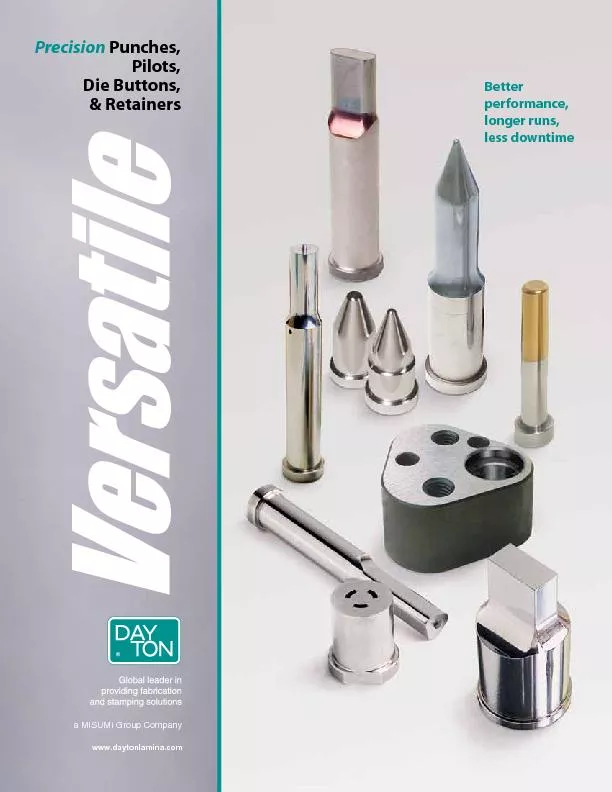
/
Precision Punches,Pilots,Die Buttons,Better performance, longer runs, Precision Punches,Pilots,Die Buttons,Better performance, longer runs,

Precision Punches,Pilots,Die Buttons,Better performance, longer runs, - PDF document

pasty-toler
pasty-toler . @pasty-toler
Follow
452 views
Uploaded On 2016-07-16

Precision Punches,Pilots,Die Buttons,Better performance, longer runs, - PPT Presentation

2 wwwdaytonlaminacom Dayton Progress Corporation HOW TO ORDER Versatile Precision Products5 VPR 37 1223 P1875 W1325 Versatile Punches Pilots and are built to e ID: 406119

2 www.daytonlamina.com Dayton Progress Corporation HOW ORDER Versatile

Share:

Link:

Embed:

Download Presentation from below link

Download Pdf The PPT/PDF document "Precision Punches,Pilots,Die Buttons,Bet..." is the property of its rightful owner. Permission is granted to download and print the materials on this web site for personal, non-commercial use only, and to display it on your personal computer provided you do not modify the materials and that you retain all copyright notices contained in the materials. By downloading content from our website, you accept the terms of this agreement.


Presentation Transcript

2 www.daytonlamina.com Dayton Progress Corporation HOW TO ORDER Versatile Precision Products5 VPR 37 1223 P.1875 W.1325 Versatile Punches, Pilots, and are built to exact tolerances and con-centricity to provide superior align-ment, better performance, longer runs, and less downtime. Dayton Versatile products are considered “top-of-the-line” by regular users, and are mainstays in heavy industries with high-demand applications, such as automotive and major appliance manufacturing.Versatile punches and die buttons provide three times better alignment than other major brands, thus assur-ing longer runs and better part performance. Versatile die buttons with tapered relief have no overhand and no step (unlike conventional counter-bored relief); provide positive slug control; and never fail due to lack of support of the cutting edge.Dayton’s Versatile precision product line includes: Punches (slug ejection punches); Regular Punches; Up Pilots; Straight and Blank Punches; Clospace Punches; Guide Bushings; and others, including and Locking Standard sizes and standard alterations are shown in this catalog within individual product sections. is a guaranteed method for reducing the risk of pulling slugs to the die surface during withdrawal of the punch. A series of grooves is designed inside the die buttons (see drawing). There, the slugs are trapped until they fall freely through the relief. The use of Dayton Slug Control has no effect on hole size, and will not require any changes in current regrind practices.Each page contains detailed instruc-tions on how to order specific Dayton Versatile products. Individual drawings show product shape, dimensions, tolerances, and concentricity. When ordering, you are asked to specify quantity, type, shank and length codes (for example), and other applicable data. In the example below, the type specified is “VPR.”“V” stands for Versatile, “P” stands for punch, and “R” stands for rectangle. 37 is the press-fit diameter, which is coded by the first two digits of the decimal equivalent (.375"). 12 is the shank length, which is coded by inches and quarter-inches (one inch and two quarters). 23 is the overall length, coded by inches and quarter-inches. Finally, P.1875 and W.1325 represent the point or hole size dimensions. Punches, pilots, and die buttons are available in sizes other than those listed in the catalog. When ordering, you are asked to specify differentdesignations for various non-standard dimensions. For example, if the P and W dimensions are outside the standard range, an “X” is placed in front of the P or W dimension, e.g., “XP” and/or “XW.” If the point length is other than standard, designate “XB” for the point length. See the foldout tabs in the individual product sections for these and other special order designations. DPPWW Qty.Type L ® Jektole is a registered trademark of Dayton Progress Corporation.TM All Triliteral Designators are trademarks of Dayton Progress Corporation.©2007 Dayton Progress Corporation. All Rights Reserved. PXPXW www.daytonlamina.com 3 Dayton Progress Corporation KD_/KH_ EDM 19 VRP Retainers 20VRT/VRTS Retainers 21Single-head/True-Location 4, 5Regular 6, 7VPA Pilots 10, 11VUAC/VPAC Pilots 12, 13VJB/VPB Blanks 14, 15VYX/VUX Straight Straight/Regular/BlanksMEX/MFX/MGX 25 MDX/MHX VQX/VFQ Classified Shapes 22, 23Shear Angles 29 Locking Devices 30, 31Form Shapes 32, 33 Data 34 (cont'd) HJROX KYVNZ PunchMatrix  Each page contains detailed instructions on how to order specific Dayton Versatile products. In addition, use the following chart to define the product as a part number.Classified shapes (83 common shapes, no detailing required) are available on all punches, solid die but-tons, and guide bushings as indicated in this catalog. See pp. 22, 23 for more information and special instructions. Also, see individual product pages and pp. 30, 31 for additional information on orientation and views.Normal grinding methods produce: .007 max fillet on the punch —matching corner shape on the die button..007 max fillet on the die button — matching corner shape on the punch. 12 .1250 18 .1875 25 .2500 31 .3125 37 .3750 43 .4375 50 .5000 62 .6250 75 .7500 87 .8750 100 1.0000 125 1.2500 150 1.5000 200 2.0000 225 2.2500 Product Series Length Point or Hole Size Type Catalog Number Dimensions As Specified1223 P.1875, W.1325 Code DCode DCode D 3 LA°+.020+.00590°0° L+.020+.010 A°.04 L+.020+.005 A° L+.020 A° 90°0 ° A° L+.020+.005 width 90° L A° 0° +.020 4 www.daytonlamina.com Dayton Progress Corporation Dayton Progress Corporation 3 3Contents JektolePunchesRegularPunchesRegular PilotsPositive Pick-UpPilotsCompact PilotsPunch BlanksStraight &Clospace PunchesDie ButtonsRetainersClassified Shapes/Miscellaneous Jektole® Punches TypeVJ_ –.0000 .0003 +.0–.00++.010+.005+.010+.00–.0.0.0+.0002+.0004 D+.125Press-In Lead.5RLP*.188BFilleD*.125 when D = .1875 .020 ShankCodeRoundShape JektoleGroup Min.XPRangeMin.Min. Max.W P/G1.251.501.752.002.252.502.753.003.253.503.754.004.25 4.504.755.005.255.505.756.006.256.50 .1875.2500.3125.3750.50.050.080.115.158.062-.1874.093-.2499.125-.3124.187-.3749.062.080.115.158 .062- .1875 .093 - .2500 .125 - .3125 .187 - .37500311101211131220132120222123223023313032313332403341 4042414342504351505251535260J2 .1875.2500.3125.3750.4375.5000.6250.7500.87501.0000.75.050.080.115.158.158.158.235.300.350.400.062-.1874.093-.2499.125-.3124.187-.3749.187-.4374.225-.4999.310-.6249.390-.7499.440-.8749.485-.9999.062.080.115.158.158.158.235.235.235.235 .062- .1875 .093 - .2500 .125 - .3125 .187 - .3750 .187 - .4375 .250 - .5000 .282 - .6250 .312 - .7500 .343 - .8750 .375 -1.0000031210131120122113222023213022312332303331403241 334240434150425143525053516052615362J2 .1875.2500.3125.3750.4375.5000.6250.7500.87501.00001.00.058.080.115.158.158.158.235.300.350.400.062-.1874.093-.2499.125-.3124.187-.3749.187-.4374.225-.4999.310-.6249.390-.7499.440-.8749.485-.9999.093.093.115.158.158.158.235.235.235.235 .093 - .1875 .093 - .2500 .125 - .3125 .187 - .3750 .187 - .4375 .250 - .5000 .282 - .6250 .312 - .7500 .343 - .8750 .375-1.000003131020112112221323203021312232233330403141 324233434050415142524353506051615262J2 .2500.3125.3750.4375.5000.6250.7500.87501.00001.25.080.115.158.158.158.235.300.350.400.093-.2499.125-.3124.187-.3749.187-.4374.225-.4999.310-.6249.390-.7499.440-.8749.485-.9999.093.115.158.158.158.235.235.235.235.093 - .2500 .125 - .3125 .187 - .3750 .187 - .4375 .250 - .5000 .282 - .6250 .312 - .7500 .343 - .8750 .375-1.00000320102111221223133020312132223323403041 314232433350405141524253436050615162 .3125.3750.4375.5000.6250.7500.87501.00001.50.115.158.158.158.235.300.350.400.125-.3124.187-.3749.187-.4374.225-.4999.310-.6249.390-.7499.440-.8749.485-.9999.115.158.158.158.235.235.235.235 .125 - .3125 .187 - .3750 .187 - .4375 .250 - .5000 .282 - .6250 .312 - .7500 .343 - .8750 .375-1.0000032110221123123013312032213322402341 304231433250335140524153426043615062 **See .34 for additional information. www.daytonlamina.com 5 Dayton Progress Corporation VJX VJO VJR VJK VJH VJJ VJN VJV VJY VJZ G2R= R (Specify 2 Note: The standard location of a key flat is at 0°. See p. for more information on flats and dowel slots. HOW TO ORDER Specify: Qty. Type D Code L P (or P&W) Example: 2 VJX 50 1020 P.375 PS 1 VJR 37 0312 P.321, W.189 A2, X2 0 (X2)90ReflectedViewD Jektole punches permit doubling punch to die button clearance; produce up to three times the number of hits between sharpenings; and reduce burr heights. Jektole punches are available in sizes other than those shown in the chart to the left. Jektole® Punches ShankCodeRoundShape JektoleGroup Min.XPRangeMin.Min. Max.W P/G1.251.501.752.002.252.502.753.003.253.503.754.004.25 4.504.755.005.255.505.756.006.256.50 .1875.2500.3125.3750.50.050.080.115.158.062-.1874.093-.2499.125-.3124.187-.3749.062.080.115.158 .062- .1875 .093 - .2500 .125 - .3125 .187 - .37500311101211131220132120222123223023313032313332403341 4042414342504351505251535260J2 .1875.2500.3125.3750.4375.5000.6250.7500.87501.0000.75.050.080.115.158.158.158.235.300.350.400.062-.1874.093-.2499.125-.3124.187-.3749.187-.4374.225-.4999.310-.6249.390-.7499.440-.8749.485-.9999.062.080.115.158.158.158.235.235.235.235 .062- .1875 .093 - .2500 .125 - .3125 .187 - .3750 .187 - .4375 .250 - .5000 .282 - .6250 .312 - .7500 .343 - .8750 .375 -1.0000031210131120122113222023213022312332303331403241 334240434150425143525053516052615362J2 .1875.2500.3125.3750.4375.5000.6250.7500.87501.00001.00.058.080.115.158.158.158.235.300.350.400.062-.1874.093-.2499.125-.3124.187-.3749.187-.4374.225-.4999.310-.6249.390-.7499.440-.8749.485-.9999.093.093.115.158.158.158.235.235.235.235 .093 - .1875 .093 - .2500 .125 - .3125 .187 - .3750 .187 - .4375 .250 - .5000 .282 - .6250 .312 - .7500 .343 - .8750 .375-1.000003131020112112221323203021312232233330403141 324233434050415142524353506051615262J2 .2500.3125.3750.4375.5000.6250.7500.87501.00001.25.080.115.158.158.158.235.300.350.400.093-.2499.125-.3124.187-.3749.187-.4374.225-.4999.310-.6249.390-.7499.440-.8749.485-.9999.093.115.158.158.158.235.235.235.235.093 - .2500 .125 - .3125 .187 - .3750 .187 - .4375 .250 - .5000 .282 - .6250 .312 - .7500 .343 - .8750 .375-1.00000320102111221223133020312132223323403041 314232433350405141524253436050615162 .3125.3750.4375.5000.6250.7500.87501.00001.50.115.158.158.158.235.300.350.400.125-.3124.187-.3749.187-.4374.225-.4999.310-.6249.390-.7499.440-.8749.485-.9999.115.158.158.158.235.235.235.235 .125 - .3125 .187 - .3750 .187 - .4375 .250 - .5000 .282 - .6250 .312 - .7500 .343 - .8750 .375-1.0000032110221123123013312032213322402341 304231433250335140524153426043615062Surface Coatings & Treatments Some catalog products can be coated to increase hardness, reduce galling, and improve wear and/or corrosion resistance. DayTride (XN)—a low-cost surface application that treats all exposed surfaces. Ideal for punches and die buttons. Provides high dimensional stability. Approx. hardness: RC73. DayTiN (XNT)—applied via PVD (physical vapor deposition). Provides extreme hardness (hard as carbide) and excellent lubricity when used with a lubricant. Not recommended for stainless steel, copper, or nickel. Approx. hardness: *Vickers 2300.DayTAN (XAN)—ultra-hard, high-aluminum PVD coating. Absorbs shear stress and provides high temperature resistance. Ideal for HSLA, dual phase, and TRIP steels. Approx. hardness: *Vickers 3400.TiCN (XCN)—very hard PVD, thin film. Provides ultra hardness (harder than carbide) and superior abrasive wear resistance. Approx. hardness: *Vickers 3000. XNM—PVD, solid film. Produces lower coefficient of friction than other coatings. Provides excellent lubricity. Approx. hard-ness: *Vickers 2000. XNP—the ultimate coating for extrusion and forming applica-tions. Also works well in shaving operations. Tolerance is ± .0002. Approx. hardness: *Vickers 3100.DayKool (XCR)—cryogenic steel conditioning process, used primarily with hard, thick materials. Improves strength, tough-ness, and dimensional stability. CrN (CRN)—excellent adhesion, high toughness, and good corrosion resistance. Primary applications are metal forming (copper, brass, bronze), metal die casting, and plastic injection molding. Approx. hardness: *Vickers 1800-2100.ZertonPlus (XNA)—excellent wear resistance, thermal shock stability and hot hardness. Approx. hardness *Vickers 3200.XNAProgress (XNAP)—ultra-hard PVD coating that absorbs shear stress; provides excellent high-temperature resistance. Ideal for stamping where tools are exposed to extreme stress profiles. A good alternative to TD coating without the dimen-sional changes associated with that process. Approx hardness: *Vickers 3200.Diamond Like Carbon Coating (XCD)—combines high hard-ness with an extremely low coefficient of friction. Good pro-tection against abrasive & adhesive wear. Approx. hardness *Vickers 5000. Code/Delivery MaterialXN —DayTride+ 3 daysM2, PS4 & PSXNT—DayTiN+ 3 daysM2, PS4 & PSXAN—DayTAN+ 4 daysM2, PS4 & PSXCN —TiCN+ daysM2, PS4 & PSXNM+12 daysM2, PS4 & PSXNP+ daysM2, PS4 & PSXCR —DayKooldayM2, PS4 & PSCRNdaysM2, PS4 & PSXNA —ZertonPlusdaysM2, PS4 & PSXNAP—XNAProgresdaysM2, PS4 & PSXCDdaysM2, PS4 & PS* Vickers used when RC exceeds 80.DayTride and DayTiN are registered trademarks of Dayton Progress.DayTAN, DayKool, and ZertonPlus are trademarks of Dayton Progress. www.daytonlamina.comDayton Progress Corporation 6 Dayton Progress Corporation 4.755.005.255.505.756.006.256.506.757.00-.1250-.1875-.2500-.3125.125 -.375040424143425043515052515352601.0000.350.440-.8749-.1250-.1875-.2500-.3125.125 -.3750-.4375-.5000-.6250-.7500-.8750.375 -1.000040434150425143525053516052615362606361701.00001.00.350.440-.8749-.1250-.1875-.2500-.3125-.3750-.4375-.5000-.6250-.7500-.8750.375 -1.000033434050415142524353506051615262536360701.00001.25.350.440-.8749 -.1250-.1875-.2500-.3125-.3750-.4375-.5000-.6250-.7500-.8750.375 -1.000032433350405141524253436050615162526353701.00001.50.350.440-.8749-.1875-.2500-.3125-.3750-.4375-.5000-.6250-.7500343 -.8750.375 -1.00003143325033514052415342604361506251635270 –.0000 .0003 +.0–.0+.0+.0+.005+.010+.00–.01.01.02+.0002+ .0004 D+.125Press-In Lead.5RLP*.188BFilleD*.125 when D = .1250 or .1875 1. Calculate (D-P)/2. 2. Find (D-P)/2 value on left side of chart. 3. Follow line over to intersection point on radius blend line. 4. Read LRB value on bottom of chart. Example:P=.175(D-P)/2=(.375–.175)/2=.100Following the .100 line on chart over the radius the LRB to be approximately .300. 5XP, XW P and W DimensionsSmaller than StandardPoint LengthXB XPXWP .75 Min. B XB P XPXWP .75 Min. B XB P Head diameter does not change with body diameter.Shank Dia. 18 25 31 37 43 50 62 75 87 100Min. XD .172 .218 .282 .344 .376 .438 .562 .688 .813 .938 XT TTXH.75 min.(Ref.)XLLLL B length. To maintain “B,” specify “XLB.”Same as XT except head thick ness tolerance is S XD XJ+3 days For XBB, add three days to delivery. XB XBB XB XBB .500 .400 .300 .200 .100 .300.200 .100 DBSBLR P Point .500- .751- 1.001- 1.251- 1.501- - .500- .751- 1.001- 1.251- 1.501- Length .750 1.000 1.250 1.500 1.625 2.000 .750 1.000 1.250 1.500 1.625Type Min. P (Rounds) Min. W (Shapes)18 VJ_ .050 .058 .062 .093 25 VJ_ .080 .080 .080 .080 .093 .093 31 VJ_ .115 .115 .115 .115 .115 .115 .115 .115 .115 .115 37 VJ_ .158 .158 .158 .158 .158 .158 .158 .158 .158 .158 43 VJ_ .158 .158 .158 .158 .158 .158 .158 .158 .158 .158 50 VJ_ .158 .158 .158 .158 .158 .158 .158 .158 .158 .158 62 VJ_ .235 .235 .235 .235 .235 .235 .235 .235 .235 .235 .235 75 VJ_ .300 .300 .300 .300 .300 .300 .235 .235 .235 .235 .235 87 VJ_ .350 .350 .350 .350 .350 .350 .235 .235 .235 .235 .235 100 VJ_ .400 .400 .400 .400 .400 .400 .235 .235 .235 .235 .235 Shank Dia.D 18 25 31 37 43 50 62 75 87 100Thickness T .125 .125 .125 .188 .188 .188 .250 .250 .250 .250 XTKXD See page 35 for Shear Angles. www.daytonlamina.comDayton Progress CorporationDayton Progress Corporation 4.755.005.255.505.756.006.256.506.757.00-.1250-.1875-.2500-.3125.125 -.375040424143425043515052515352601.0000.350.440-.8749-.1250-.1875-.2500-.3125.125 -.3750-.4375-.5000-.6250-.7500-.8750.375 -1.000040434150425143525053516052615362606361701.00001.00.350.440-.8749-.1250-.1875-.2500-.3125-.3750-.4375-.5000-.6250-.7500-.8750.375 -1.000033434050415142524353506051615262536360701.00001.25.350.440-.8749 -.1250-.1875-.2500-.3125-.3750-.4375-.5000-.6250-.7500-.8750.375 -1.000032433350405141524253436050615162526353701.00001.50.350.440-.8749-.1875-.2500-.3125-.3750-.4375-.5000-.6250-.7500343 -.8750.375 -1.00003143325033514052415342604361506251635270 –.0000 .0003 +.0–.0+.0+.0+.005+.010+.00–.01.01.02+.0002+ .0004 D+.125Press-In Lead.5RLP*.188BFilleD*.125 when D = .1250 or .1875 1. Calculate (D-P)/2. 2. Find (D-P)/2 value on left side of chart. 3. Follow line over to intersection point on radius blend line. 4. Read LRB value on bottom of chart. XPXWP.75 Min. B XB P XPXWP.75 Min. B XB P Head diameter does not change with body diameter.Shank Dia. 18 25 31 37 43 50 62 75 87 100Min. XD .172 .218 .282 .344 .376 .438 .562 .688 .813 .938 XTTTXH.75 min.(Ref.)XLLLL B length. To maintain “B,” specify “XLB.”Same as XT except head thick ness tolerance is XD For XBB, add three days to delivery. .500 .400 .300 .200 .100 .300.200 .100 DBSBLR P Point .500- .751- 1.001- 1.251- 1.501- - .500- .751- 1.001- 1.251- 1.501- Length .750 1.000 1.250 1.500 1.625 2.000 .750 1.000 1.250 1.500 1.625Type Min. P (Rounds) Min. W (Shapes)18 VJ_ .050 .058 .062 .093 25 VJ_ .080 .080 .080 .080 .093 .093 31 VJ_ .115 .115 .115 .115 .115 .115 .115 .115 .115 .115 37 VJ_ .158 .158 .158 .158 .158 .158 .158 .158 .158 .158 43 VJ_ .158 .158 .158 .158 .158 .158 .158 .158 .158 .158 50 VJ_ .158 .158 .158 .158 .158 .158 .158 .158 .158 .158 62 VJ_ .235 .235 .235 .235 .235 .235 .235 .235 .235 .235 .235 75 VJ_ .300 .300 .300 .300 .300 .300 .235 .235 .235 .235 .235 87 VJ_ .350 .350 .350 .350 .350 .350 .235 .235 .235 .235 .235 100 VJ_ .400 .400 .400 .400 .400 .400 .235 .235 .235 .235 .235Shank Dia.D 18 25 31 37 43 50 62 75 87 100Thickness T .125 .125 .125 .188 .188 .188 .250 .250 .250 .250 6 www.daytonlamina.com Dayton Progress Corporation Dayton Progress Corporation TypeVP_Regular Punches ShankCodePointLgth.BRoundShape L DMin.XPRangePMin.XWMin.WMax.P/G1.251.501.752.002.252.502.753.003.253.503.754.004.25 4.755.005.255.505.756.006.256.506.757.00 -.1250-.1875-.2500-.3125.125 -.3750 4042414342504351505251535260 1.0000.350.440-.8749-.1250-.1875-.2500-.3125.125 -.3750-.4375-.5000-.6250-.7500-.8750.375 -1.0000 4043415042514352505351605261536260636170 1.00001.00.350.440-.8749-.1250-.1875-.2500-.3125-.3750-.4375-.5000-.6250-.7500-.8750.375 -1.0000 3343405041514252435350605161526253636070 1.00001.25.350.440-.8749-.1250-.1875-.2500-.3125-.3750-.4375-.5000-.6250-.7500-.8750.375 -1.0000 3243335040514152425343605061516252635370 1.00001.50.350.440-.8749-.1875-.2500-.3125-.3750-.4375-.5000-.6250-.7500343 -.8750.375 -1.0000 3143325033514052415342604361506251635270 –.0000 .0003 +.0–.0+.0+.0+.005+.010+.00–.01.01.02+.0002+ .0004 D+.125 Press-In Lead .5RLP*.188BFilleD*.125 when D = .1250 or .1875 1. Calculate (D-P)/2. 2. Find (D-P)/2 value on left side of chart. 3. Follow line over to intersection point on radius blend line. 4. Read LRB value on bottom of chart. XPXWP.75 Min. B XB P XPXWP.75 Min. B XB P Head diameter does not change with body diameter.Shank Dia. 18 25 31 37 43 50 62 75 87 100Min. XD .172 .218 .282 .344 .376 .438 .562 .688 .813 .938 XTTTXH.75 min.(Ref.)XLLLL B length. To maintain “B,” specify “XLB.”Same as XT except head thick ness tolerance is XD For XBB, add three days to delivery. .500 .400 .300 .200 .100 .300.200 .100 DBSBLR P Point .500- .751- 1.001- 1.251- 1.501- - .500- .751- 1.001- 1.251- 1.501- Length .750 1.000 1.250 1.500 1.625 2.000 .750 1.000 1.250 1.500 1.625Type Min. P (Rounds) Min. W (Shapes)18 VJ_ .050 .058 .062 .093 25 VJ_ .080 .080 .080 .080 .093 .093 31 VJ_ .115 .115 .115 .115 .115 .115 .115 .115 .115 .115 37 VJ_ .158 .158 .158 .158 .158 .158 .158 .158 .158 .158 43 VJ_ .158 .158 .158 .158 .158 .158 .158 .158 .158 .158 50 VJ_ .158 .158 .158 .158 .158 .158 .158 .158 .158 .158 62 VJ_ .235 .235 .235 .235 .235 .235 .235 .235 .235 .235 .235 75 VJ_ .300 .300 .300 .300 .300 .300 .235 .235 .235 .235 .235 87 VJ_ .350 .350 .350 .350 .350 .350 .235 .235 .235 .235 .235 100 VJ_ .400 .400 .400 .400 .400 .400 .235 .235 .235 .235 .235Shank Dia.D 18 25 31 37 43 50 62 75 87 100Thickness T .125 .125 .125 .188 .188 .188 .250 .250 .250 .250 www.daytonlamina.com 7 Dayton Progress Corporation Regular Punches Code Note: The standard location of a key flat is at 0°. See p. for more information on flats and dowel slots. HOW TO ORDER Specify: Qty. Type D Code L P (or P&W) Example: 2 VPX 37 1020 P.250 A2 1 VPJ 12 0312 P.103, W.065 M2, XN 0 (X2)90ReflectedViewD Regular Versatile punches provide three times better alignment than other major brands; offer longer tool life; and can significantly improve finished part quality. ShankCodePointLgth.BRoundShape L DMin.XPRangePMin.XWMin.WMax.P/G1.251.501.752.002.252.502.753.003.253.503.754.004.25 4.755.005.255.505.756.006.256.506.757.00 -.1250-.1875-.2500-.3125.125 -.3750 4042414342504351505251535260 1.0000.350.440-.8749-.1250-.1875-.2500-.3125.125 -.3750-.4375-.5000-.6250-.7500-.8750.375 -1.0000 4043415042514352505351605261536260636170 1.00001.00.350.440-.8749-.1250-.1875-.2500-.3125-.3750-.4375-.5000-.6250-.7500-.8750.375 -1.0000 3343405041514252435350605161526253636070 1.00001.25.350.440-.8749-.1250-.1875-.2500-.3125-.3750-.4375-.5000-.6250-.7500-.8750.375 -1.0000 3243335040514152425343605061516252635370 1.00001.50.350.440-.8749-.1875-.2500-.3125-.3750-.4375-.5000-.6250-.7500343 -.8750.375 -1.0000 3143325033514052415342604361506251635270 G2R= VPX VPO VPR VPK VPH VPJ VPNVPV VPY VPZR (Specify Regular Versatile punches are available in sizes other than those shown in the chart to the left. When ordering, you are asked to specify different designations for various non-standard dimensions. For example, if the P and W dimensions are out-side the standard range, an “X” is placed in front of the P or W dimension, e.g., “XP” and/or “XW.” If the point length is longer than standard, desig-nate “XB” as the point length. Also see “Standard Alterations” on the front of the pullout tab in this section for other special order designators. Surface Coatings & Treatments Some catalog products can be coated to increase hardness, reduce galling, and improve wear and/or corrosion resistance. DayTride (XN)—a low-cost surface application that treats all exposed surfaces. Ideal for punches and die buttons. Provides high dimensional stability. Approx. hardness: RC73. DayTiN (XNT)—applied via PVD (physical vapor deposition). Provides extreme hardness (hard as carbide) and excellent lubricity when used with a lubricant. Not recommended for stainless steel, copper, or nickel. Approx. hardness: *Vickers 2300.DayTAN (XAN)—ultra-hard, high-aluminum PVD coating. Absorbs shear stress and provides high temperature resistance. Ideal for HSLA, dual phase, and TRIP steels. Approx. hardness: *Vickers 3400.TiCN (XCN)—very hard PVD, thin film. Provides ultra hardness (harder than carbide) and superior abrasive wear resistance. Approx. hardness: *Vickers 3000. XNM—PVD, solid film. Produces lower coefficient of friction than other coatings. Provides excellent lubricity. Approx. hard-ness: *Vickers 2000. XNP—the ultimate coating for extrusion and forming applica-tions. Also works well in shaving operations. Tolerance is ± .0002. Approx. hardness: *Vickers 3100.DayKool (XCR)—cryogenic steel conditioning process, used primarily with hard, thick materials. Improves strength, tough-ness, and dimensional stability. CrN (CRN)—excellent adhesion, high toughness, and good corrosion resistance. Primary applications are metal forming (copper, brass, bronze), metal die casting, and plastic injection molding. Approx. hardness: *Vickers 1800-2100.ZertonPlus (XNA)—excellent wear resistance, thermal shock stability and hot hardness. Approx. hardness *Vickers 3200.XNAProgress (XNAP)—ultra-hard PVD coating that absorbs shear stress; provides excellent high-temperature resistance. Ideal for stamping where tools are exposed to extreme stress profiles. A good alternative to TD coating without the dimen-sional changes associated with that process. Approx hardness: *Vickers 3200.Diamond Like Carbon Coating (XCD)—combines high hard-ness with an extremely low coefficient of friction. Good pro-tection against abrasive & adhesive wear. Approx. hardness *Vickers 5000. Code/Delivery MaterialXN —DayTride+ 3 daysM2, PS4 & PSXNT—DayTiN+ 3 daysM2, PS4 & PSXAN—DayTAN+ 4 daysM2, PS4 & PSXCN —TiCN+ daysM2, PS4 & PSXNM+12 daysM2, PS4 & PSXNP+ daysM2, PS4 & PSXCR —DayKooldayM2, PS4 & PSCRNdaysM2, PS4 & PSXNA —ZertonPlusdaysM2, PS4 & PSXNAP—XNAProgresdaysM2, PS4 & PSXCDdaysM2, PS4 & PS* Vickers used when RC exceeds 80.DayTride and DayTiN are registered trademarks of Dayton Progress.DayTAN, DayKool, and ZertonPlus are trademarks of Dayton Progress. www.daytonlamina.comDayton Progress Corporation 8 Dayton Progress Corporation Regular Pilots ShankPointLgth.RoundMin.Range1.251.501.752.002.252.502.753.003.253.503.754.004.254.504.755.005.255.505.756.006.256.506.757.00.050.050.061.061.061.061 - .1250.061 - .1875.061 - .2500.092 - .3125.124 - .3750031110121113122013212022212322302331303231333240334140424143425043515052515352601.0000.050.050.061.061.061.092.124.234.299.349.399.061 - .1250.061 - .1875.061 - .2500.092 - .3125.124 - .3750.186 - .4375.224 - .5000.309 - .6250.389 - .7500.439 - .8750.484 -1.0000031210131120122113222023213022312332303331403241334240434150425143525053516052615362606361701.0000.057.057.061.061.061.092.124.234.299.349.399.061 - .1250.061 - .1875.061 - .2500.092 - .3125.124 - .3750.186 - .4375.224 - .5000.309 - .6250.389 - .7500.439 - .8750.484 -1.000003131020112112221323203021312232233330403141324233434050415142524353506051615262536360701.0000.074.074.079.092.092.092.124.234.299.349.399.092 - .1250.092 - .1875.092 - .2500.092 - .3125.124 - .3750.186 - .4375.224 - .5000.309 - .6250.389 - .7500.439 - .8750.484 -1.00000320102111221223133020312132223323403041314232433350405141524253436050615162526353701.0000.092.092.092.124.124.124.234.299.349.399.124 - .1875.124 - .2500.124 - .3125.124 - .3750.186 - .4375.224 - .5000.309 - .6250.389 - .7500.439 - .8750.484 -1.000003211022112312301331203221332240234130423143325033514052415342604361506251635270 .0003 –.0000 End ofCut Punch Parabolic Point Shapefor Smooth Pick-up ActionFull Diameter Lead.119Under.238.238Point Diameters .25 .2 Over.238 .0+.06–.00++.01+.005+.010+.00– .01.01.02+.0002+.0004 D+.125Press-In Lead.5RLP**.188BFilleD**.125 when D = .1250 or .1875.25**Length slightlyless for Dias.under .238Punch Length (Ref.).09 Full Dia. Lead PThanLess.0 12 VP_ .042*.058 .075 .062 .062 .093 18 VP_ .042 .058 .075 .093 .062 .062 .093 .125 25 VP_ .062 .062 .080 .093 .062 .062 .093 .125 31 VP_ .062 .062 .093 .093 .125 .062 .093 .093 .125 .195 37 VP_ .062 .062 .093 .125 .125 .250 .312 .080 .109 .125 .125 .195 43 VP_ .093 .093 .093 .125 .125 .250 .312 .109 .109 .141 .172 .195 50 VP_ .125 .125 .125 .125 .125 .250 .312 .125 .125 .141 .172 .195 62 VP_ .235 .235 .235 .235 .235 .235 .312 .375 .235 .235 .235 .235 .235 75 VP_ .300 .300 .300 .300 .300 .300 .343 .406 .235 .235 .235 .235 .235 87 VP_ .350 .350 .350 .350 .350 .350 .375 .437 .235 .235 .235 .235 .235 100 VP_ .400 .400 .400 .400 .400 .400 .400 .437 .235 .235 .235 .235 .235 *.031 for .500 B XHXLLLL B XT TT.75 min(Ref. Head diameter does not change with body diameter.Shank Dia. 12 18 25 31 37 43 50 62 75 87 100 .251 .313 .376 .438 .562 .688 .813 .938 1. Calculate (D-P)/2. 2. Find (D-P)/2 value on left side of chart. 3. Follow line over to intersection point on radius blend line. 4. Read LRB value on bottom of chart. Example:P=.175(D-P)/2=(.375–.175)/2=.100Following the .100 line on chart over the radius the LRB to be approximately .300. .500 .400 .300 .200 .100 .300.200 .100 DBSBLR P XPXWP .75 Min. B XB P XPXWP .75 Min. B XB PXP, XW P and W DimensionsSmaller than StandardStandard AlterationsRegular Punches .500- .751- 1.001- 1.251- 1.501- 1.626- 2.001- 2.501 .500- .751- 1.001- 1.251- 1.501- 1.626-Length .750 1.000 1.250 1.500 1.625 2.000 2.500 3.000 .750 1.000 1.250 1.500 1.625 2.000XB XBB X3B XB XBB For XBB and X3B, add three days to delivery. Code Type length. To maintain “B,” specify “XLB.”Same as XT except head thick ness tolerance is Shank Dia.D 18 25 31 37 43 50 62 75 87 100Thickness T .125 .125 .125 .188 .188 .188 .250 .250 .250 .250 XTK See page 35 for Shear Angles. 8 www.daytonlamina.com Dayton Progress Corporation Dayton Progress Corporation Regular Pilots TypeVPT ShankPointLgth.Round L Min.Range1.251.501.752.002.252.502.753.003.253.503.754.004.254.50 4.755.005.255.505.756.006.256.506.757.00 .050.050.061.061.061.061 - .1250.061 - .1875.061 - .2500.092 - .3125.124 - .375003111012111312201321202221232230233130323133324033414042 414342504351505251535260 1.0000.050.050.061.061.061.092.124.234.299.349.399.061 - .1250.061 - .1875.061 - .2500.092 - .3125.124 - .3750.186 - .4375.224 - .5000.309 - .6250.389 - .7500.439 - .8750.484 -1.00000312101311201221132220232130223123323033314032413342 4043415042514352505351605261536260636170 1.0000.057.057.061.061.061.092.124.234.299.349.399.061 - .1250.061 - .1875.061 - .2500.092 - .3125.124 - .3750.186 - .4375.224 - .5000.309 - .6250.389 - .7500.439 - .8750.484 -1.0000031310201121122213232030213122322333304031413242 3343405041514252435350605161526253636070 1.0000.074.074.079.092.092.092.124.234.299.349.399.092 - .1250.092 - .1875.092 - .2500.092 - .3125.124 - .3750.186 - .4375.224 - .5000.309 - .6250.389 - .7500.439 - .8750.484 -1.000003201021112212231330203121322233234030413142 3243335040514152425343605061516252635370 1.0000.092.092.092.124.124.124.234.299.349.399.124 - .1875.124 - .2500.124 - .3125.124 - .3750.186 - .4375.224 - .5000.309 - .6250.389 - .7500.439 - .8750.484 -1.00000321102211231230133120322133224023413042 3143325033514052415342604361506251635270 .0003 –.0000 When P=D, shank tolerance applies. End ofCut Punch Parabolic Point Shapefor Smooth Pick-up ActionFull Diameter Lead.119Under.238.238Point Diameters .25 .2 Over.238 .0 +.06–.00++.01+.005+.010+.00– .01.01.02+.0002+.0004 D+.125Press-In Lead.5RLP**.188BFilleD**.125 when D = .1250 or .1875.25**Length slightlyless for Dias.under .238Punch Length (Ref.).09 Full Dia. Lead PThanLess .0 12 VP_ .042*.058 .075 .062 .062 .093 18 VP_ .042 .058 .075 .093 .062 .062 .093 .125 25 VP_ .062 .062 .080 .093 .062 .062 .093 .125 31 VP_ .062 .062 .093 .093 .125 .062 .093 .093 .125 .195 37 VP_ .062 .062 .093 .125 .125 .250 .312 .080 .109 .125 .125 .195 43 VP_ .093 .093 .093 .125 .125 .250 .312 .109 .109 .141 .172 .195 50 VP_ .125 .125 .125 .125 .125 .250 .312 .125 .125 .141 .172 .195 62 VP_ .235 .235 .235 .235 .235 .235 .312 .375 .235 .235 .235 .235 .235 75 VP_ .300 .300 .300 .300 .300 .300 .343 .406 .235 .235 .235 .235 .235 87 VP_ .350 .350 .350 .350 .350 .350 .375 .437 .235 .235 .235 .235 .235 100 VP_ .400 .400 .400 .400 .400 .400 .400 .437 .235 .235 .235 .235 .235 *.031 for .500 B XHXLLLL B XTTT.75 min(Ref. XD Head diameter does not change with body diameter.Shank Dia. 12 18 25 31 37 43 50 62 75 87 100 .251 .313 .376 .438 .562 .688 .813 .938 1. Calculate (D-P)/2. 2. Find (D-P)/2 value on left side of chart. 3. Follow line over to intersection point on radius blend line. 4. Read LRB value on bottom of chart. .500 .400 .300 .200 .100 .300.200 .100 DBSBLR P XPXWP.75 Min. B XB P XPXWP.75 Min. B XB P .500- .751- 1.001- 1.251- 1.501- 1.626- 2.001- 2.501 .500- .751- 1.001- 1.251- 1.501- 1.626-Length .750 1.000 1.250 1.500 1.625 2.000 2.500 3.000 .750 1.000 1.250 1.500 1.625 2.000XB XBB X3B XB XBBFor XBB and X3B, add three days to delivery.Code Type length. To maintain “B,” specify “XLB.”Same as XT except head thick ness tolerance is Shank Dia.D 18 25 31 37 43 50 62 75 87 100Thickness T .125 .125 .125 .188 .188 .188 .250 .250 .250 .250 www.daytonlamina.com 9 Dayton Progress Corporation Regular Pilots Code HOW TO ORDER Regular Versatile pilots are built to exact tolerances; the parabolic point shape allows for smooth pick-up action; and pilots offer a wide range of unique punching and fabrication applications. ShankPointLgth.RoundMin.Range1.251.501.752.002.252.502.753.003.253.503.754.004.254.50 4.755.005.255.505.756.006.256.506.757.00 .050.050.061.061.061.061 - .1250.061 - .1875.061 - .2500.092 - .3125.124 - .375003111012111312201321202221232230233130323133324033414042 414342504351505251535260 1.0000.050.050.061.061.061.092.124.234.299.349.399.061 - .1250.061 - .1875.061 - .2500.092 - .3125.124 - .3750.186 - .4375.224 - .5000.309 - .6250.389 - .7500.439 - .8750.484 -1.00000312101311201221132220232130223123323033314032413342 4043415042514352505351605261536260636170 1.0000.057.057.061.061.061.092.124.234.299.349.399.061 - .1250.061 - .1875.061 - .2500.092 - .3125.124 - .3750.186 - .4375.224 - .5000.309 - .6250.389 - .7500.439 - .8750.484 -1.0000031310201121122213232030213122322333304031413242 3343405041514252435350605161526253636070 1.0000.074.074.079.092.092.092.124.234.299.349.399.092 - .1250.092 - .1875.092 - .2500.092 - .3125.124 - .3750.186 - .4375.224 - .5000.309 - .6250.389 - .7500.439 - .8750.484 -1.000003201021112212231330203121322233234030413142 3243335040514152425343605061516252635370 1.0000.092.092.092.124.124.124.234.299.349.399.124 - .1875.124 - .2500.124 - .3125.124 - .3750.186 - .4375.224 - .5000.309 - .6250.389 - .7500.439 - .8750.484 -1.00000321102211231230133120322133224023413042 3143325033514052415342604361506251635270 End ofCut Punch Parabolic Point Shapefor Smooth Pick-up ActionFull Diameter Lead.119Under.238.238Point Diameters .25 .2 Over.238 .0 +.06–.00++.01+.005+.010+.00– .01.01.02+.0002+.0004 D+.125Press-In Lead.5RLP**.188BFilleD**.125 when D = .1250 or .1875.25**Length slightlyless for Dias.under .238Punch Length (Ref.).09 Full Dia. Lead P ThanLess .0 Regular Versatile pilots are available in sizes other than those shown in the chart to the left. When ordering, you are asked to specify different designations for various non-standard dimensions. For example, if the P dimension is outside the standard range, an “X” is placed in front of the P dimension, e.g., “XP.” If the point length is longer than standard, designate “XB” as the point length. Also see “Standard Alterations” on the front of the pullout tab in this section for other special order designators.Specify: Qty. Type D Code L P Steel Example: 3 VPT 37 1020 P.251 M2 2 VPT 43 1322 P.300 M2, XNT Surface Coatings & Treatments Some catalog products can be coated to increase hardness, reduce galling, and improve wear and/or corrosion resistance. DayTride (XN)—a low-cost surface application that treats all exposed surfaces. Ideal for punches and die buttons. Provides high dimensional stability. Approx. hardness: RC73. DayTiN (XNT)—applied via PVD (physical vapor deposition). Provides extreme hardness (hard as carbide) and excellent lubricity when used with a lubricant. Not recommended for stainless steel, copper, or nickel. Approx. hardness: *Vickers 2300.DayTAN (XAN)—ultra-hard, high-aluminum PVD coating. Absorbs shear stress and provides high temperature resistance. Ideal for HSLA, dual phase, and TRIP steels. Approx. hardness: *Vickers 3400.TiCN (XCN)—very hard PVD, thin film. Provides ultra hardness (harder than carbide) and superior abrasive wear resistance. Approx. hardness: *Vickers 3000. XNM—PVD, solid film. Produces lower coefficient of friction than other coatings. Provides excellent lubricity. Approx. hard-ness: *Vickers 2000. XNP—the ultimate coating for extrusion and forming applica-tions. Also works well in shaving operations. Tolerance is ± .0002. Approx. hardness: *Vickers 3100.DayKool (XCR)—cryogenic steel conditioning process, used primarily with hard, thick materials. Improves strength, tough-ness, and dimensional stability. CrN (CRN)—excellent adhesion, high toughness, and good corrosion resistance. Primary applications are metal forming (copper, brass, bronze), metal die casting, and plastic injection molding. Approx. hardness: *Vickers 1800-2100.ZertonPlus (XNA)—excellent wear resistance, thermal shock stability and hot hardness. Approx. hardness *Vickers 3200.XNAProgress (XNAP)—ultra-hard PVD coating that absorbs shear stress; provides excellent high-temperature resistance. Ideal for stamping where tools are exposed to extreme stress profiles. A good alternative to TD coating without the dimen-sional changes associated with that process. Approx hardness: *Vickers 3200.Diamond Like Carbon Coating (XCD)—combines high hard-ness with an extremely low coefficient of friction. Good pro-tection against abrasive & adhesive wear. Approx. hardness *Vickers 5000. Code/Delivery MaterialXN —DayTride+ 3 daysM2 & PSXNT—DayTiN+ 3 daysM2 & PSXAN—DayTAN+ 4 daysM2 & PSXCN —TiCN+ daysM2 & PSXNM+12 daysM2 & PSXNP+ daysM2 & PSXCR —DayKooldayM2 & PSCRNdaysM2 & PSXNA —ZertonPlusdaysM2 & PSXNAP—XNAProgresdaysM2 & PSXCDdaysM2 & PS* Vickers used when RC exceeds 80.DayTride and DayTiN are registered trademarks of Dayton Progress.DayTAN, DayKool, and ZertonPlus are trademarks of Dayton Progress. www.daytonlamina.comDayton Progress Corporation 10 Dayton Progress Corporation TypeVPAPositive Pick-Up Pilots If you require a length other than shown, designate “XL” (original B length will be maintained). Example: You require a length of 3.600. Order 375, then show XL 3.600. See “How to Order” example on the next page. XL is available down to 1.375. Note shank length limitation of .75. (B length may be shorter than shown when XL is under the shortest length shown.) ShankPointLgth.Round*N L A2/M2 M2 only L M2 onlyMin.Range2.252.502.753.003.253.503.754.004.254.504.755.005.255.505.756.006.256.506.757.00 .1875 .2500 .3125 .3750 .4375 .5000 .6250 .7500 .87501.0000.75.050.061.061.061.092.124.234.299.349.399.061 - .1875.061 - .2500.092 - .3125.124 - .3750.186 - .4375.224 - .5000.309 - .6250.389 - .7500.439 - .8750.484 -1.0000 .18 .25 .31 .37 .43 .50 .62 .75 .871.00.0977.1432.1883.2342.2793.3252.4162.5072.5982.689212211322202321302231233230333140324133424043415042514352505351605261536260636170 .1875 .2500 .3125 .3750 .4375 .5000 .6250 .7500 .87501.00001.00.057.061.061.061.092.124.234.299.349.399.061 - .1875.061 - .2500.092 - .3125.124 - .3750.186 - .4375.224 - .5000.309 - .6250.389 - .7500.439 - .8750.484 -1.0000 .18 .25 .31 .37 .43 .50 .62 .75 .871.00.0977.1432.1883.2342.2793.3252.4162.5072.5982.689211211222132320302131223223333040314132423343405041514252435350605161526253636070 .1875 .2500 .3125 .3750 .4375 .5000 .6250 .7500 .87501.00001.25.074.079.092.092.092.124.234.299.349.399.092 - .1875.092 - .2500.092 - .3125.124 - .3750.186 - .4375.224 - .5000.309 - .6250.389 - .7500.439 - .8750.484 -1.0000 .18 .25 .31 .37 .43 .50 .62 .75 .871.00.0977.1432.1883.2342.2793.3252.4162.5072.5982.68921122122313302031213222332340304131423243335040514152425343605061516252635370 –.0000 .0003 P+.0002–.0000+.0–.0+.02– .00+.005+.010+.00–.01.01.02+.0002+.0004D+.125Press-In Lead.5R*.188 BFilleDN40Included PL*.125 when D = .1875 *N =[(P-.057)/.728]+.132 when “P” dimension is less than “Pn” shown in chart. Standard AlterationsRegular Pilots 1. Calculate (D-P)/2. 2. Find (D-P)/2 value on left side of chart. 3. Follow line over to intersection point on radius blend line. 4. Read LRB value on bottom of chart. Example:P=.175(D-P)/2=(.375–.175)/2=.100Following the .100 line on chart over the radius the LRB to be approximately .300. P XP .75Min.XBBP XHXLLB XT TT.75 min.(Ref.) P XP Point .500- .751- 1.001- 1.251- 1.501- 1.6261- 2.0001- 2.5001- Length .750 1.000 1.250 1.500 1.625 2.0000 2.5000 3.0000 Code Type Min. P (Rounds) 12 VPT .050 .057 .074 18 VPT .050 .057 .074 .092 25 VPT .061 .061 .079 .092 31 VPT .061 .061 .092 .092 .124 37 VPT .061 .061 .092 .124 .124.186 .249 .311 43 VPT .092 .092 .092 .124 .124.186 .249 .311 50 VPT .124 .124 .124 .124 .124.186 .249 .311 62 VPT .234 .234 .234 .234 .234.234 .311 .374 75 VPT .299 .299 .299 .299 .299.299 .342 .405 87 VPT .349 .349 .349 .349 .349.349 .374 .436100 VPT .399 .399 .399 .399 .399.399 .399 .499 Head diameter does not change with body diameter.Shank Dia. 12 18 25 31 37 43 50 62 75 87 100 .251 .313 .376 .438 .562 .688 .813 .938 .500 .400 .300 .200 .100 .300.200 .100 DBSBLR P For XBB and X3B, add three days to delivery. length. To maintain “B,” specify “XLB.”Same as XT except head thick ness tolerance is Shank Dia.D 18 25 31 37 43 50 62 75 87 100Thickness T .125 .125 .125 .188 .188 .188 .250 .250 .250 .250 XTK 10 www.daytonlamina.com Dayton Progress Corporation Dayton Progress Corporation TypeVPAPositive Pick-Up Pilots If you require a length other than shown, designate “XL” (original B length will be maintained). Example: You require a length of 3.600. Order 375, then show XL 3.600. See “How to Order” example on the next page. XL is available down to 1.375. Note shank length limitation of .75. (B length may be shorter than shown when XL is under the shortest length shown.) ShankPointLgth.Round*N L A2/M2 M2 only L M2 only Min.Range2.252.502.753.003.253.503.754.004.254.504.755.00 5.255.505.756.006.256.506.757.00 .1875 .2500 .3125 .3750 .4375 .5000 .6250 .7500 .87501.0000.75.050.061.061.061.092.124.234.299.349.399.061 - .1875.061 - .2500.092 - .3125.124 - .3750.186 - .4375.224 - .5000.309 - .6250.389 - .7500.439 - .8750.484 -1.0000 .18 .25 .31 .37 .43 .50 .62 .75 .871.00.0977.1432.1883.2342.2793.3252.4162.5072.5982.6892122113222023213022312332303331403241334240434150 42514352505351605261536260636170 .1875 .2500 .3125 .3750 .4375 .5000 .6250 .7500 .87501.00001.00.057.061.061.061.092.124.234.299.349.399.061 - .1875.061 - .2500.092 - .3125.124 - .3750.186 - .4375.224 - .5000.309 - .6250.389 - .7500.439 - .8750.484 -1.0000 .18 .25 .31 .37 .43 .50 .62 .75 .871.00.0977.1432.1883.2342.2793.3252.4162.5072.5982.6892112112221323203021312232233330403141324233434050 41514252435350605161526253636070 .1875 .2500 .3125 .3750 .4375 .5000 .6250 .7500 .87501.00001.25.074.079.092.092.092.124.234.299.349.399.092 - .1875.092 - .2500.092 - .3125.124 - .3750.186 - .4375.224 - .5000.309 - .6250.389 - .7500.439 - .8750.484 -1.0000 .18 .25 .31 .37 .43 .50 .62 .75 .871.00.0977.1432.1883.2342.2793.3252.4162.5072.5982.689211221223133020312132223323403041314232433350 40514152425343605061516252635370 –.0000 .0003 P+.0002–.0000+.0–.0+.02– .00+.005+.010+.00–.01.01.02+.0002+.0004D+.125Press-In Lead.5R*.188 BFilleDN40Included P L*.125 when D = .1875*N =[(P-.057)/.728]+.132 when “P” dimension is less than “Pn” shown in chart. 1. Calculate (D-P)/2. 2. Find (D-P)/2 value on left side of chart. 3. Follow line over to intersection point on radius blend line. 4. Read LRB value on bottom of chart. P XP.75Min.XBBP XHXLLB XTTT.75 min.(Ref.) P XP.75Min.XBBP Point .500- .751- 1.001- 1.251- 1.501- 1.6261- 2.0001- 2.5001-Length .750 1.000 1.250 1.500 1.625 2.0000 2.5000 3.0000Code Type Min. P (Rounds) 12 VPT .050 .057 .074 18 VPT .050 .057 .074 .092 25 VPT .061 .061 .079 .092 31 VPT .061 .061 .092 .092 .124 37 VPT .061 .061 .092 .124 .124.186 .249 .311 43 VPT .092 .092 .092 .124 .124.186 .249 .311 50 VPT .124 .124 .124 .124 .124.186 .249 .311 62 VPT .234 .234 .234 .234 .234.234 .311 .374 75 VPT .299 .299 .299 .299 .299.299 .342 .405 87 VPT .349 .349 .349 .349 .349.349 .374 .436100 VPT .399 .399 .399 .399 .399.399 .399 .499 XD Head diameter does not change with body diameter.Shank Dia. 12 18 25 31 37 43 50 62 75 87 100 .251 .313 .376 .438 .562 .688 .813 .938 .500 .400 .300 .200 .100 .300.200 .100 DBSBLR P For XBB and X3B, add three days to delivery.length. To maintain “B,” specify “XLB.”Same as XT except head thick ness tolerance is Shank Dia.D 18 25 31 37 43 50 62 75 87 100Thickness T .125 .125 .125 .188 .188 .188 .250 .250 .250 .250 www.daytonlamina.com 11 Dayton Progress Corporation Positive Pick-Up Pilots HOW TO ORDER Dayton Versatile positive pick-up pilots provide smoother pick-up without the risk of distorting the hole; in addition, the unique design moves the stock farther than conventional pilots. sizes other than those shown in the chart to the left. When ordering, you are asked to specify different designations for various non-standard dimensions. For example, if the P dimension is outside the standard range, an “X” is placed in front of the P dimension, e.g., “XP.” If the point length is other than standard, designate “XB” as the point length. Also see “Standard Alterations” on the front of the pullout tab in this section for other special order designators. ShankPointLgth.Round*N L A2/M2 M2 only L M2 onlyMin.Range2.252.502.753.003.253.503.754.004.254.504.755.00 5.255.505.756.006.256.506.757.00 .1875 .2500 .3125 .3750 .4375 .5000 .6250 .7500 .87501.0000.75.050.061.061.061.092.124.234.299.349.399.061 - .1875.061 - .2500.092 - .3125.124 - .3750.186 - .4375.224 - .5000.309 - .6250.389 - .7500.439 - .8750.484 -1.0000 .18 .25 .31 .37 .43 .50 .62 .75 .871.00.0977.1432.1883.2342.2793.3252.4162.5072.5982.6892122113222023213022312332303331403241334240434150 42514352505351605261536260636170 .1875 .2500 .3125 .3750 .4375 .5000 .6250 .7500 .87501.00001.00.057.061.061.061.092.124.234.299.349.399.061 - .1875.061 - .2500.092 - .3125.124 - .3750.186 - .4375.224 - .5000.309 - .6250.389 - .7500.439 - .8750.484 -1.0000 .18 .25 .31 .37 .43 .50 .62 .75 .871.00.0977.1432.1883.2342.2793.3252.4162.5072.5982.6892112112221323203021312232233330403141324233434050 41514252435350605161526253636070 .1875 .2500 .3125 .3750 .4375 .5000 .6250 .7500 .87501.00001.25.074.079.092.092.092.124.234.299.349.399.092 - .1875.092 - .2500.092 - .3125.124 - .3750.186 - .4375.224 - .5000.309 - .6250.389 - .7500.439 - .8750.484 -1.0000 .18 .25 .31 .37 .43 .50 .62 .75 .871.00.0977.1432.1883.2342.2793.3252.4162.5072.5982.689211221223133020312132223323403041314232433350 40514152425343605061516252635370 Code Geometry providessmoother pick-upwithout risk ofdistortion of hole.Greater positioning —moves stock farther thanconventional pilots. P+.0002– .0000+.0–.0+.02–.00+.00+.010+.00–.01.0.02+.0002+ .000D+.125Press-In Lead.5R.188BFillet D N40Included P L Specify: Qty. Type D Code L P XL Steel Example: 6 VPA 100 1 Day VPA Surface Coatings & Treatments Some catalog products can be coated to increase hardness, reduce galling, and improve wear and/or corrosion resistance. DayTride (XN)—a low-cost surface application that treats all exposed surfaces. Ideal for punches and die buttons. Provides high dimensional stability. Approx. hardness: RC73. DayTiN (XNT)—applied via PVD (physical vapor deposition). Provides extreme hardness (hard as carbide) and excellent lubricity when used with a lubricant. Not recommended for stainless steel, copper, or nickel. Approx. hardness: *Vickers 2300.DayTAN (XAN)—ultra-hard, high-aluminum PVD coating. Absorbs shear stress and provides high temperature resistance. Ideal for HSLA, dual phase, and TRIP steels. Approx. hardness: *Vickers 3400.TiCN (XCN)—very hard PVD, thin film. Provides ultra hardness (harder than carbide) and superior abrasive wear resistance. Approx. hardness: *Vickers 3000. XNM—PVD, solid film. Produces lower coefficient of friction than other coatings. Provides excellent lubricity. Approx. hard-ness: *Vickers 2000. XNP—the ultimate coating for extrusion and forming applica-tions. Also works well in shaving operations. Tolerance is ± .0002. Approx. hardness: *Vickers 3100.DayKool (XCR)—cryogenic steel conditioning process, used primarily with hard, thick materials. Improves strength, tough-ness, and dimensional stability. CrN (CRN)—excellent adhesion, high toughness, and good corrosion resistance. Primary applications are metal forming (copper, brass, bronze), metal die casting, and plastic injection molding. Approx. hardness: *Vickers 1800-2100.ZertonPlus (XNA)—excellent wear resistance, thermal shock stability and hot hardness. Approx. hardness *Vickers 3200.XNAProgress (XNAP)—ultra-hard PVD coating that absorbs shear stress; provides excellent high-temperature resistance. Ideal for stamping where tools are exposed to extreme stress profiles. A good alternative to TD coating without the dimen-sional changes associated with that process. Approx hardness: *Vickers 3200.Diamond Like Carbon Coating (XCD)—combines high hard-ness with an extremely low coefficient of friction. Good pro-tection against abrasive & adhesive wear. Approx. hardness *Vickers 5000. Code/Delivery MaterialXN —DayTride+ 3 daysXNT—DayTiN+ 3 daysXAN—DayTAN+ 4 daysXCN —TiCN+ daysXNM+12 daysXNP+ daysXCR —DayKooldayCRNdaysXNA —ZertonPlusdaysXNAP—XNAProgresdaysXCDdays* Vickers used when RC exceeds 80.DayTride and DayTiN are registered trademarks of Dayton Progress.DayTAN, DayKool, and ZertonPlus are trademarks of Dayton Progress. www.daytonlamina.comDayton Progress Corporation 12 Dayton Progress Corporation Specify: Qty. Type D Code L P Alt. SteelExample: 25 VUAC — 11 VPAC 62 100 2 Days TypeVUACStraightCompact Positive Pick-Up PilotsMaterialSteel: .0.0+.0002-.0000+.02-.0HP.188+.005+.010+.00-.0 TypeHeadRange P.625.750.8751.001.1251.2501.375VUACStraight.375 .438.500.562.625.750.8751.00125 .1865- .2500 .25- .3130 .3131- .3750 .3751 .4380 .4381- .5000 .5001- .6250 .6251- .7500 .7501- .8750 .8751- .0000 .25 .31 .37 .43 .50 .87.00100112125137 Standard AlterationsPositive Pick-up Pilots .500 .400 .300 .200 .100 .300.200 .100 DBSBLR P 1. Calculate (D-P)/2. 2. Find (D-P)/2 value on left side of chart. 3. Follow line over to intersection point on radius blend line. 4. Read LRB value on bottom of chart. Example:P=.175(D-P)/2=(.375–.175)/2=.100Following the .100 line on chart over the radius the LRB to be approximately .300. Head Diameter does not change with body diameter.Shank Dia. 18 25 31 37 43 50 62 75 87 100Min. XD .126 .188 .251 .313 .376 .438 .562 .688 .813 .938 For XBB and X3B, add three days to delivery. Same as XT except head thick ness tolerance XD P P XP XB B .75Min XH XL L B XTTT.75 min.(Ref.) P P XP XB B .75Min Point Length Other than StandardSpecify XB, XBB, or X3B and length .500- .626- .751- .876- 1.001- 1.126- 1.251- 1.376- 1.501- 1.626- 2.001- 2.501- Length .625 .750 .875 1.000 1.125 1.250 1.375 1.500 1.625 2.000 2.500 3.000 Code Type 18 VPA .050 .050 .057 .057 .074 .074 .092 .092 25 VPA .061 .061 .061 .061 .079 .079 .092 .092 31 VPA .061 .061 .061 .061 .092 .092 .092 .092 .124 .186 37 VPA .061 .061 .061 .061 .092 .092 .124 .124 .124 .186 .249 .311 43 VPA .092 .092 .092 .092 .092 .092 .124 .124 .124 .186 .249 .311 50 VPA .124 .124 .124 .124 .124 .124 .124 .124 .124 .186 .249 .311 62 VPA .234 .234 .234 .234 .234 .234 .234 .234 .234 .234 .311 .374 75 VPA .299 .299 .299 .299 .299 .299 .299 .299 .299 .299 .342 .405 87 VPA .349 .349 .349 .349 .349 .349 .349 .349 .349 .349 .374 .436 100 VPA .399 .399 .399 .399 .399 .399 .399 .399 .399 .399 .399 .436 XB Shank Dia.D 18 25 31 37 43 50 62 75 87 100Thickness T .125 .125 .125 .188 .188 .188 .250 .250 .250 .250 XTK 12 www.daytonlamina.com Dayton Progress Corporation Dayton Progress Corporation HOW TO ORDER Specify: Qty. Type D Code L P Alt. SteelExample: 25 VUAC — 11 VPAC 62 100 2 Days TypeVUACStraightCompact Positive Pick-Up Pilots Material .0.0+.0002-.0000+.02-.0HP.188+.005+.010+.00-.0*Any length is available within catalog range. Specify “XL” and length. TypeHeadRange P.625.750.8751.001.1251.2501.375VUACStraight.375.438.500.562.625.750.8751.00125 .1865- .2500 .25- .3130 .3131- .3750 .3751 .4380 .4381- .5000 .5001- .6250 .6251- .7500 .7501- .8750 .8751- .0000 .25 .31 .37 .43 .50 .87.00100112125137 Standard AlterationsPositive Pick-up Pilots .500 .400 .300 .200 .100 .300.200 .100 DBSBLR P 1. Calculate (D-P)/2. 2. Find (D-P)/2 value on left side of chart. 3. Follow line over to intersection point on radius blend line. 4. Read LRB value on bottom of chart.Head Diameter does not change with body diameter.Shank Dia. 18 25 31 37 43 50 62 75 87 100Min. XD .126 .188 .251 .313 .376 .438 .562 .688 .813 .938For XBB and X3B, add three days to delivery.Same as XT except head thick ness tolerance XD P P XP XB B .75Min XH XL L B XTTT.75 min.(Ref.) P P XP XB B .75Min .500- .626- .751- .876- 1.001- 1.126- 1.251- 1.376- 1.501- 1.626- 2.001- 2.501- Length .625 .750 .875 1.000 1.125 1.250 1.375 1.500 1.625 2.000 2.500 3.000 Code Type 18 VPA .050 .050 .057 .057 .074 .074 .092 .092 25 VPA .061 .061 .061 .061 .079 .079 .092 .092 31 VPA .061 .061 .061 .061 .092 .092 .092 .092 .124 .186 37 VPA .061 .061 .061 .061 .092 .092 .124 .124 .124 .186 .249 .311 43 VPA .092 .092 .092 .092 .092 .092 .124 .124 .124 .186 .249 .311 50 VPA .124 .124 .124 .124 .124 .124 .124 .124 .124 .186 .249 .311 62 VPA .234 .234 .234 .234 .234 .234 .234 .234 .234 .234 .311 .374 75 VPA .299 .299 .299 .299 .299 .299 .299 .299 .299 .299 .342 .405 87 VPA .349 .349 .349 .349 .349 .349 .349 .349 .349 .349 .374 .436 100 VPA .399 .399 .399 .399 .399 .399 .399 .399 .399 .399 .399 .436Shank Dia.D 18 25 31 37 43 50 62 75 87 100Thickness T .125 .125 .125 .188 .188 .188 .250 .250 .250 .250 www.daytonlamina.com 13 Dayton Progress Corporation Compact Positive Pick-Up Pilots .0.0+.0002+.0002-.0000+.02-.0(L1)H+.03-.0+.00-.0.188+.005.1.12RP Type ShankCodeHead Min.Range P **L.625.750.8751.001.1251.2501.375VPACPointed.2500.3125.3750.4375.5000.6250.7500.8750.00031100.375.500.562.625.750.875125 .092 .092 .092 .092124 .234 .299 .349 .399.1500.2499.1870.3124.2250.3749.2650.4374 .3000.4999.3750.6249.4500.7499.5250.8749.6000.9999.25.31.37.43.50.87.001432.1883.2342.2793.3252.4162.5072.5982.6892100112125137 Specify “XL” and length. The L .12 is maintained. .12 is standard, use alteration code .0003 P to D MaterialSteel: TypeVPACPointedFeatures/BenefitsDayton Versatile Compact Positive Pick-Up Pilots—mounted in a guided stripper—provide exceptional resistance to lateral deflec-tion. A typical longer pilot may have several inches of exposed, unsupported surface. As bending or forming takes place, this lateral strength of the pilot—as well as the function of the other die set components—can be compromised. Dayton Compact Pilots provide virtually no unsupported surface that is susceptible to sideways movement, stress, or wear. Pilots always adjust the pilot during regrinding.Dayton Compact Pilots are rigid during use; last longer; and are ideally suited for high-demand applications. ()“” is less than “Pn” shown in chart.* Vickers used when RC exceeds 80.DayTride and DayTiN are registered trademarks of Dayton Progress.DayTAN, DayKool, and ZertonPlus are trademarks of Dayton Progress. Surface Coatings & Treatments Some catalog products can be coated to increase hardness, reduce galling, and improve wear and/or corrosion resistance. DayTride (XN)—a low-cost surface application that treats all exposed surfaces. Ideal for punches and die buttons. Provides high dimensional stability. Approx. hardness: RC73. DayTiN (XNT)—applied via PVD (physical vapor deposition). Provides extreme hardness (hard as carbide) and excellent lubricity when used with a lubricant. Not recommended for stainless steel, copper, or nickel. Approx. hardness: *Vickers 2300.DayTAN (XAN)—ultra-hard, high-aluminum PVD coating. Absorbs shear stress and provides high temperature resistance. Ideal for HSLA, dual phase, and TRIP steels. Approx. hardness: *Vickers 3400.TiCN (XCN)—very hard PVD, thin film. Provides ultra hardness (harder than carbide) and superior abrasive wear resistance. Approx. hardness: *Vickers 3000. XNM—PVD, solid film. Produces lower coefficient of friction than other coatings. Provides excellent lubricity. Approx. hard-ness: *Vickers 2000. XNP—the ultimate coating for extrusion and forming applica-tions. Also works well in shaving operations. Tolerance is ± .0002. Approx. hardness: *Vickers 3100.DayKool (XCR)—cryogenic steel conditioning process, used primarily with hard, thick materials. Improves strength, tough-ness, and dimensional stability. CrN (CRN)—excellent adhesion, high toughness, and good corrosion resistance. Primary applications are metal forming (copper, brass, bronze), metal die casting, and plastic injection molding. Approx. hardness: *Vickers 1800-2100.ZertonPlus (XNA)—excellent wear resistance, thermal shock stability and hot hardness. Approx. hardness *Vickers 3200.XNAProgress (XNAP)—ultra-hard PVD coating that absorbs shear stress; provides excellent high-temperature resistance. Ideal for stamping where tools are exposed to extreme stress profiles. A good alternative to TD coating without the dimen-sional changes associated with that process. Approx hardness: *Vickers 3200.Diamond Like Carbon Coating (XCD)—combines high hard-ness with an extremely low coefficient of friction. Good pro-tection against abrasive & adhesive wear. Approx. hardness *Vickers 5000. Code/Delivery MaterialXN —DayTride+ 3 daysM2 & PSXNT—DayTiN+ 3 daysM2 & PSXAN—DayTAN+ 4 daysM2 & PSXCN —TiCN+ daysM2 & PSXNM+12 daysM2 & PSXNP+ daysM2 & PSXCR —DayKooldayM2 & PSCRNdaysM2 & PSXNA —ZertonPlusdaysM2 & PSXNAP—XNAProgresdaysM2 & PSXCDdaysM2 & PS www.daytonlamina.comDayton Progress Corporation 14 Dayton Progress Corporation **See p.32 for additional information. TypeVJBJektole®TypeVPBRegular VPB +.01+.02+.005+.010+.00–.01.01.02+.0002+.0004D+.125L*.188FilleDVJB +.01+.02+.005+.010+.00–.01.01.02+.0002+.0004D+.125L*.188FilleDB(Ref.)*.125 when D = .125 or .1875*.125 when D = .125 or .1875 ShankPointLgth.JektoleGroup1.251.501.752.002.252.502.753.003.253.503.754.004.254.504.755.005.255.505.756.006.256.506.757.00VJB.1875.2500.3125.3750.500311101211131220132120222123223023313032313332403341404241434250435150525153526053616062.1875.2500.3125.3750.4375.5000.6250.7500.87501.0000100.75031210131120122113222023213022312332303331403241334240434150425110043525053516052615362.1875.2500.3125.3750.4375.5000.6250.7500.87501.00001001.0003131020112112221323203021312232233330403141324233434050415110042524353506051625262.2500.3125.3750.4375.5000.6250.7500.87501.00001001.250320102111221223133020312132223323403041314232433350405110041524253436050615162.3125.3750.4375.5000.6250.7500.87501.00001001.50032110221123123013312032213322402341304231433250335110040524153426043615062VPB.1250.1875.2500.3125.3750.4375.5000.6250.7500.87501.0000100N/A125150175200225250275300325350375400425450475500525100550575600625650675700N/AType 13Standard AlterationsCompact PilotsXPP DimensionSmaller than Standard Same as XT except head thick ness tolerance XBR L1 Longer than Standard.12R is maintained. XP L1.12R P XP L1.12R P XTTTXH Reduced Shank Diameter (VPAC only)Head Diameter does not change with body diameter.Shank Dia. 25 31 37 43 50 62 75 87 100Min. XD .188 .251 .313 .376 .438 .562 .688 .813 .938 XD 14 www.daytonlamina.com Dayton Progress Corporation Dayton Progress Corporation **See p.32 for additional information. TypeVJBJektole®TypeVPBRegular VPB +.01+.02+.005+.010+.00–.01.01.02+.0002+.0004D+.125L*.188FilleD VJB +.01+.02+.005+.010+.00–.01.01.02+.0002+.0004D+.125L*.188FilleDB(Ref.)*.125 when D = .125 or .1875 *.125 when D = .125 or .1875 ShankPointLgth. JektoleGroup 1.251.501.752.002.252.502.753.003.253.503.754.004.254.504.755.005.25 5.505.756.006.256.506.757.00 VJB.1875.2500.3125.3750.5003111012111312201321202221232230233130323133324033414042414342504351 50525153526053616062 .1875.2500.3125.3750.4375.5000.6250.7500.87501.0000100.750312101311201221132220232130223123323033314032413342404341504251 10043525053516052615362 .1875.2500.3125.3750.4375.5000.6250.7500.87501.00001001.00031310201121122213232030213122322333304031413242334340504151 10042524353506051625262 .2500.3125.3750.4375.5000.6250.7500.87501.00001001.2503201021112212231330203121322233234030413142324333504051 10041524253436050615162 .3125.3750.4375.5000.6250.7500.87501.00001001.500321102211231230133120322133224023413042314332503351 10040524153426043615062 VPB.1250.1875.2500.3125.3750.4375.5000.6250.7500.87501.0000100N/A125150175200225250275300325350375400425450475500525 100550575600625650675700N/A Type Same as XT except head thick ness tolerance XP L1.12RP XP L1.12RP XTTTXH (L1) Reduced Shank Diameter (VPAC only)Head Diameter does not change with body diameter.Shank Dia. 25 31 37 43 50 62 75 87 100Min. XD .188 .251 .313 .376 .438 .562 .688 .813 .938 XD www.daytonlamina.com 15 Dayton Progress Corporation Features/BenefitsDayton Punch Blanks are an ideal cost-effective alternative in applications where Dayton standard shape configurations or our classified shapes do not meet customer requirements. Blanks—available in a full be custom-ground to meet virtually any customer requirement. CodePunch BlanksJektole® & Regular MaterialAll heads are drawn to RC 40-55. VPB +.01+.02+.005+.010+.00–.01.01.02+.0002+.0004D+.125L*.188FilleD VJB +.01+.02+.005+.010+.00–.01.01+.0002+.0004D+.125L*.188FilleDB(Ref.)*.125 when D = .125 or .1875 *.125 when D = .125 or .1875 HOW TO ORDER Specify: Qty. Type D Code L SteelExample: 4 VJB 50 1020 A23 VPB 37 200 M2 1 Day ShankPointLgth. JektoleGroup 1.251.501.752.002.252.502.753.003.253.503.754.004.254.504.755.005.25 5.505.756.006.256.506.757.00 VJB.1875.2500.3125.3750.5003111012111312201321202221232230233130323133324033414042414342504351 50525153526053616062 .1875.2500.3125.3750.4375.5000.6250.7500.87501.0000100.750312101311201221132220232130223123323033314032413342404341504251 10043525053516052615362 .1875.2500.3125.3750.4375.5000.6250.7500.87501.00001001.00031310201121122213232030213122322333304031413242334340504151 10042524353506051625262 .2500.3125.3750.4375.5000.6250.7500.87501.00001001.2503201021112212231330203121322233234030413142324333504051 10041524253436050615162 .3125.3750.4375.5000.6250.7500.87501.00001001.500321102211231230133120322133224023413042314332503351 10040524153426043615062 VPB.1250.1875.2500.3125.3750.4375.5000.6250.7500.87501.0000100N/A125150175200225250275300325350375400425450475500525 100550575600625650675700N/A Surface Coatings & Treatments Some catalog products can be coated to increase hardness, reduce galling, and improve wear and/or corrosion resistance. DayTride (XN)—a low-cost surface application that treats all exposed surfaces. Ideal for punches and die buttons. Provides high dimensional stability. Approx. hardness: RC73. DayTiN (XNT)—applied via PVD (physical vapor deposition). Provides extreme hardness (hard as carbide) and excellent lubricity when used with a lubricant. Not recommended for stainless steel, copper, or nickel. Approx. hardness: *Vickers 2300.DayTAN (XAN)—ultra-hard, high-aluminum PVD coating. Absorbs shear stress and provides high temperature resistance. Ideal for HSLA, dual phase, and TRIP steels. Approx. hardness: *Vickers 3400.TiCN (XCN)—very hard PVD, thin film. Provides ultra hardness (harder than carbide) and superior abrasive wear resistance. Approx. hardness: *Vickers 3000. XNM—PVD, solid film. Produces lower coefficient of friction than other coatings. Provides excellent lubricity. Approx. hard-ness: *Vickers 2000. XNP—the ultimate coating for extrusion and forming applica-tions. Also works well in shaving operations. Tolerance is ± .0002. Approx. hardness: *Vickers 3100.DayKool (XCR)—cryogenic steel conditioning process, used primarily with hard, thick materials. Improves strength, tough-ness, and dimensional stability. CrN (CRN)—excellent adhesion, high toughness, and good corrosion resistance. Primary applications are metal forming (copper, brass, bronze), metal die casting, and plastic injection molding. Approx. hardness: *Vickers 1800-2100.ZertonPlus (XNA)—excellent wear resistance, thermal shock stability and hot hardness. Approx. hardness *Vickers 3200.XNAProgress (XNAP)—ultra-hard PVD coating that absorbs shear stress; provides excellent high-temperature resistance. Ideal for stamping where tools are exposed to extreme stress profiles. A good alternative to TD coating without the dimen-sional changes associated with that process. Approx hardness: *Vickers 3200.Diamond Like Carbon Coating (XCD)—combines high hard-ness with an extremely low coefficient of friction. Good pro-tection against abrasive & adhesive wear. Approx. hardness *Vickers 5000. Code/Delivery MaterialXN —DayTride+ 3 daysM2 & PSXNT—DayTiN+ 3 daysM2 & PSXAN—DayTAN+ 4 daysM2 & PSXCN —TiCN+ daysM2 & PSXNM+12 daysM2 & PSXNP+ daysM2 & PSXCR —DayKooldayM2 & PSCRNdaysM2 & PSXNA —ZertonPlusdaysM2 & PSXNAP—XNAProgresdaysM2 & PSXCDdaysM2 & PS* Vickers used when RC exceeds 80.DayTride and DayTiN are registered trademarks of Dayton Progress.DayTAN, DayKool, and ZertonPlus are trademarks of Dayton Progress. www.daytonlamina.comDayton Progress Corporation 16 Dayton Progress Corporation P+.0002–.0000+.01+.02+.005+.010+.00–.01.01.02HLTFilleVUX P+.0002–.0000+.0+.02+.00+.010+.00–.0.0.02HL.188FilleC Vent HoleVY Straight PunchesJektole® and Regular P Tolerance –.0000 Versatile straight and clospace punches are available in sizes other than those shown in the chart above and on p.17. When ordering, you are asked to specify different designations for various non-standard dimensions.For example, if the P dimension is outside the standard range, an “X” is placed in front of the P dimension, e.g., “XP.” Also see “Standard Alterations” on the front of the pullout tab in this section for other special order designators. RangeHeadDia.Head Thk.VentHoleJektoleGroup1.251.501.752.002.252.502.753.003.253.503.754.004.254.504.755.005.255.505.756.006.256.50VYX.1870-.2500.375 SeeDWG125150175200225250275300J2.2501-.3130.438.80125150175200225250275300325350375400.3131-.3750.500.60.85125150175200225250275300325350375400.3751-.4380.562.851.10150175200225250275300325350375400.4381-.5000.625.851.10150175200225250275300325350375400.5001-.6250.750.851.10150175200225250275300325350375400VUX.0620-.1250.1251-.1880.1881-.2500.2501-.3130.3131-.3750.3751-.4380.4381-.5000.5001-.6250.250.312.375.438.500.562.625.750.125.125.188.188.188.188.188.188N/A125150175200225250275300325350375400425450475500525550575600625650N/ASpecify: Qty. Type P L SteelExample: 5 VYX P.324 250 A2 2 VUX P.492 325 M2 15 Point LengthOther than StandardXB XPXWP .75Min. XB Head diameter does not change with body diameter.Shank Dia. 18 25 31 37 43 50 62 75 87 100Min. XD VJB .172 .218 .282 .344 .376 .438 .562 .688 .813 .938Min. XD VPB .126 .188 .251 .313 .376 .438 .562 .688 .813 .938 XT TTXH.75 min.(Ref.)XLLLL B length. To maintain “B,” specify “XB.”Same as XT except head thick ness tolerance is XD XJ+3 days For XBB, add three days to delivery. Shank Dia.D 18 25 31 37 43 50 62 75 87 100Thickness T .125 .125 .125 .188 .188 .188 .250 .250 .250 .250 XTK 16 www.daytonlamina.com Dayton Progress Corporation Dayton Progress Corporation P+.0002–.0000+.01+.02+.005+.010+.00–.01.01.02HLTFille VUX P+.0002–.0000+.0+.02+.00+.010+.00–.0.0.02HL.188FilleC Vent HoleVY Straight PunchesJektole® and Regular 1 Day P Tolerance –.0000 HOW TO ORDER Versatile straight and clospace punches are available in sizes other than those shown in the chart above and on p.17. When ordering, you are asked to specify different designations for various non-standard dimensions.For example, if the P dimension is outside the standard range, an “X” is placed in front of the P dimension, e.g., “XP.” Also see “Standard Alterations” on the front of the pullout tab in this section for other special order designators. *See p32 for additional information. RangeHeadDia.Head Thk.VentHoleJektoleGroup1.251.501.752.002.252.502.753.003.253.503.754.004.254.504.755.005.255.505.756.006.256.50VYX.1870-.2500.375 SeeDWG125150175200225250275300J2.2501-.3130.438.80125150175200225250275300325350375400.3131-.3750.500.60.85125150175200225250275300325350375400.3751-.4380.562.851.10150175200225250275300325350375400.4381-.5000.625.851.10150175200225250275300325350375400.5001-.6250.750.851.10150175200225250275300325350375400VUX.0620-.1250.1251-.1880.1881-.2500.2501-.3130.3131-.3750.3751-.4380.4381-.5000.5001-.6250.250.312.375.438.500.562.625.750.125.125.188.188.188.188.188.188N/A125150175200225250275300325350375400425450475500525550575600625650N/ASpecify: Qty. Type P L SteelExample: 5 VYX P.324 250 A2 2 VUX P.492 325 M2 15Point LengthOther than StandardXB XPXWP.75Min. XB Head diameter does not change with body diameter.Shank Dia. 18 25 31 37 43 50 62 75 87 100Min. XD VJB .172 .218 .282 .344 .376 .438 .562 .688 .813 .938Min. XD VPB .126 .188 .251 .313 .376 .438 .562 .688 .813 .938 XTTTXH.75 min.(Ref.)XLLLL B length. To maintain “B,” specify “XB.”Same as XT except head thick ness tolerance is XD For XBB, add three days to delivery.Shank Dia.D 18 25 31 37 43 50 62 75 87 100Thickness T .125 .125 .125 .188 .188 .188 .250 .250 .250 .250 www.daytonlamina.com 17 Dayton Progress Corporation –.0000 .0003 HOW TO ORDER Punches, Blanks 1 Day Specify: Qty. Type D Code L P SteelExample: 5 VCX 12 200 P.098 M2Surface Coatings & Treatments Some catalog products can be coated to increase hardness, reduce galling, and improve wear and/or corrosion resistance. DayTride (XN)—a low-cost surface application that treats all exposed surfaces. Ideal for punches and die buttons. Provides high dimensional stability. Approx. hardness: RC73. DayTiN (XNT)—applied via PVD (physical vapor deposition). Provides extreme hardness (hard as carbide) and excellent lubricity when used with a lubricant. Not recommended for stainless steel, copper, or nickel. Approx. hardness: *Vickers 2300.DayTAN (XAN)—ultra-hard, high-aluminum PVD coating. Absorbs shear stress and provides high temperature resistance. Ideal for HSLA, dual phase, and TRIP steels. Approx. hardness: *Vickers 3400.TiCN (XCN)—very hard PVD, thin film. Provides ultra hardness (harder than carbide) and superior abrasive wear resistance. Approx. hardness: *Vickers 3000. XNM—PVD, solid film. Produces lower coefficient of friction than other coatings. Provides excellent lubricity. Approx. hard-ness: *Vickers 2000. XNP—the ultimate coating for extrusion and forming applica-tions. Also works well in shaving operations. Tolerance is ± .0002. Approx. hardness: *Vickers 3100.DayKool (XCR)—cryogenic steel conditioning process, used primarily with hard, thick materials. Improves strength, tough-ness, and dimensional stability. CrN (CRN)—excellent adhesion, high toughness, and good corrosion resistance. Primary applications are metal forming (copper, brass, bronze), metal die casting, and plastic injection molding. Approx. hardness: *Vickers 1800-2100.ZertonPlus (XNA)—excellent wear resistance, thermal shock stability and hot hardness. Approx. hardness *Vickers 3200.XNAProgress (XNAP)—ultra-hard PVD coating that absorbs shear stress; provides excellent high-temperature resistance. Ideal for stamping where tools are exposed to extreme stress profiles. A good alternative to TD coating without the dimen-sional changes associated with that process. Approx hardness: *Vickers 3200.Diamond Like Carbon Coating (XCD)—combines high hard-ness with an extremely low coefficient of friction. Good pro-tection against abrasive & adhesive wear. Approx. hardness *Vickers 5000. Code/Delivery MaterialXN —DayTride+ 3 daysXNT—DayTiN+ 3 daysXAN—DayTAN+ 4 daysXCN —TiCN+ daysXNM+12 daysXNP+ daysXCR —DayKooldayCRNdaysXNA —ZertonPlusdaysXNAP—XNAProgresdaysXCDdays* Vickers used when RC exceeds 80.DayTride and DayTiN are registered trademarks of Dayton Progress.DayTAN, DayKool, and ZertonPlus are trademarks of Dayton Progress. ShankHeadDia.PointLgth.RangeTypeCode1.501.752.002.252.502.753.003.253.503.754.00Straight PunchesVXXVWXN/A.125N/A.0300-.0500150175200225250.125.0501-.0630275300325350375400.160.0631-.0940.190.0941-.1250.220.1251-.1570.250.1571-.1880.282.1881-.2190.313.2191-.2500Regular PunchesVVX.062506.125.19.0310-.0624150175200225250275300325350375400.0938.160.25.0626-.0937.1250.190.31.0939-.1249.1562.220.31.1251-.1561.187518.250.31.1563-.1874.2188.282.31.1876-.2187.2500.313.31.2189-.2499PunchBlanksVCBVVB.062506.125N/A150175200225250275300325350375400.0938.160.1250.190.1562.220.187518.250.2188.282.2500.313 www.daytonlamina.comDayton Progress Corporation 18 Dayton Progress Corporation Die Buttons .0003 TypeVN_TypeVRXTypeVR_MaterialSteel: A2, M2 (RC 60-63), PS (RC 63-65)Shown here with optional key flat. See p. 31. +.00– .01+.005+.010.0.0L.188*FilleD+.125 .125+.005+.015.125+.0002+.0004DPPress-InLead+.0002+.0004DPL.125+.01+.02*.125 when D = .1875VNX/VN__VRX/VR__ .0005 2PLandPTapered Relief—.004-.008/inch/side .012max*3P or holesunder .100Matrix Construction When P.062.125StraightLandPL.125StraightLand4Pto5P*TaperedRound ReliefTaperedRound Relief.004/inch/side.006TaperedShape Relief.004/inch/sid.006.006/inch/side.010 HOW TO ORDER G2R= V_X V_O V_R V_K V_H V_J V_N V_V V_Y V_Z R (Specify 2PLandPTapered Relief—.004-.008/inch/side .012max*3P or holesunder .100Matrix Construction When P.062.125StraightLandPL.125StraightLand4Pto5P*TaperedRound ReliefTaperedRound Relief.004/inch/side.006TaperedShape Relief.004/inch/sid.006.006/inch/side.010 2PLandPTapered Relief—.004-.008/inch/side .012max*3P or holesunder .100Die Button Construction When P.062.125StraightLandPL.125StraightLand4PtoTapered Relief.004/inch/side.006TaperedShape Relief.004/inch/sid.006Tapered Relief.006/inch/side.010 Versatile die buttons are available in sizes other than those shown in the chart above. When ordering, you are asked to specify different designations for various non-standard dimensions. For example, if the L dimension is outside the standard range, an “X” is placed in front of the L dimension, e.g., “XL.” Also see “Standard Alterations” on the front of the pullout tab in this section for other special order designators.18-100 Dia. 1 Day Specify: Qty. Type D Code L P (or P&W) Example: 4 VNR 37 112 P.207, W.126 A2, X8 3 VRO 50 137 P.3125, W.1562 M2, X2 17Overall Length Shortened Stock removal from point end.Precision Overall LengthSame as XL except overall ±.001.XLLLXH XHD L XLLL thick ness tolerance is For an explanation of the alteration codes shown above, see the “Standard Alterations, Regular Punches” on the p.7 pullout tab. AlterationCodeProductVXXVWXVCXVVXVCBVVBXBXDXHXLLLXPXTTT Clospace Punches BodyRoundShapeTypeRange P Min. Max. W P/G.500.625.750.8751.0001.1251.2501.3751.5001.6251.7501.8752.00031162175187200162175187200.5000.6250.7500162175187200100125150162175187200200225250275 XKNFor air ejection. No cost.SSee p.XJ+3 days See page 35 for Shear Angles. 18 www.daytonlamina.com Dayton Progress Corporation Dayton Progress Corporation Die Buttons .0003 TypeVN_TypeVRXTypeVR_MaterialSteel: A2, M2 (RC 60-63), PS (RC 63-65)Shown here with optional key flat. See p. 31. +.00– .01+.005+.010.0.0L.188*FilleD+.125 .125+.005+.015.125+.0002+.0004DPPress-InLead+.0002+.0004DPL.125+.01+.02*.125 when D = .1875 VNX/VN __ VRX/VR .0005 2PPTapered Relief—.004-.008/inch/side .012 *3P or holesunder .100 Matrix Construction When P.062 .125StraightLandPL .125StraightLand 4Pto5P*TaperedRound ReliefTaperedRound Relief.004/inch/side.006 TaperedShape Relief.004/inch/sid.006 .006/inch/side.010 HOW TO ORDER G2R= V_X V_O V_R V_K V_H V_J V_N V_V V_Y V_Z R (Specify 2PPTapered Relief—.004-.008/inch/side .012*3P or holesunder .100Matrix Construction When P.062.125StraightLandPL .125StraightLand 4Pto5P*TaperedTaperedRound Relief.004/inch/side.006 TaperedShape Relief.004/inch/sid.006 .006/inch/side.010 2PPTapered Relief—.004-.008/inch/side .012*3P or holesunder .100 Die Button Construction When P.062.125StraightLandPL.125StraightLand4PTapered Relief.004/inch/side.006TaperedShape Relief.004/inch/sid.006Tapered Relief.006/inch/side.010 Versatile die buttons are available in sizes other than those shown in the chart above. When ordering, you are asked to specify different designations for various non-standard dimensions. For example, if the L dimension is outside the standard range, an “X” is placed in front of the L dimension, e.g., “XL.” Also see “Standard Alterations” on the front of the pullout tab in this section for other special order designators.18-100 Dia. 1 Day Specify: Qty. Type D Code L P (or P&W) Example: 4 VNR 37 112 P.207, W.126 A2, X8 3 VRO 50 137 P.3125, W.1562 M2, X2 17Overall Length Shortened Stock removal from point end.Precision Overall LengthSame as XL except overall ±.001.XLLLXH XHD L XLLL XT/TT thick ness tolerance is For an explanation of the alteration codes shown above, see the “Standard Alterations, Regular Punches” on the p.7 pullout tab. BodyRoundShapeTypeRange P Min. Max. W P/G.500.625.750.8751.0001.1251.2501.3751.5001.6251.7501.8752.00031162175187200162175187200.5000.6250.7500162175187200100125150162175187200200225250275 XKNFor air ejection. No cost.SSee p.XJ+3 daysSee page 35 for Shear Angles. www.daytonlamina.com 19 Dayton Progress Corporation EDM Die Button Blanks TypeKHUKHE Headed TypeKDU Headless Steel: M2 (RC 60-63) .005P to D Features/Benefits L+.015–.000D+.0002+.0005PUnlessSpecifiedPress-InLead .125 L+.02–.00+.0002+.0005PUnlessSpecifiedD+.125 .188+.01–.00D+.00–.01.01R L+.015–.000D+.0002+.0005PUnlessSpecifiedPress-InLead .125 L+.02–.00+.0002+.0005PUnlessSpecifiedD+.125 .188+.01–.00 D+.00– .01.01.02R B R+.010–.000 R B 1.00 1 Day 1.50 2 Days(with XP, add 2 Days) 1.50 4 Days BodyK_UK_E**LTypeCodeStd.Optional PStd. Optional P.75.87.93*1.001.1251.251.3751.501.6251.751.8752.00 .2500.031.020.031.020.15 .156100112125137.3125.031.020.031.020.25.191.3750.031.020.031.020.25.228150162175187200.4375.031.020.031.020.25.281.5000.062.020.031.020.25.312.6250.062.020.031.093.020.031.25.391.7500.062.020.031.093.020.031.31.468.8750.062.020.031.093.020.031.31.5781.0000.062.020.031.093.020.031.31.7031.2500.062.020.031.125.020.031.37.8281.5000.062.020.031.125.031.371.0941.7500.125.020.031.125.020.031.371.4301001121251371501621751872002.0000.125.020.031.125.020.031.371.6302.2500.125.020.031.125.020.031.371.8302.5000.125.020.031.125.020.031.372.0302.7500.125.020.031.125.020.031.372.230Standard “P” will be provided, unless otherwise specified. HOW TO ORDER Specify: Qty. Type D Code L P Steel Example: 6 KDE 37 100 XP.020 M2 5 KDU 50 112 .031 M2 Dayton Slug ControlDayton Slug Control is a guaranteed method for reducing the risk of pulling slugs to the die surface during withdrawal of the punch. A series of grooves is designed inside the die button (see drawing). There, the slugs are trapped until they fall freely through the relief. The use of Dayton Slug Control has no effect on hole size, and will not require any changes in current regrind practices.Our guarantee: Use Dayton Slug Control in a stamping die now pulling slugs. If, for any reason, you are not completely satisfied, we will refund the full cost of the Slug Control alteration. (We cannot guarantee the retention of slugs when clearance exceeds 10% per side.)OrderingDayton Slug Control is easy to specify and order. Simply add the information that is unique to your application to the die button catalog number. Please specify XSC for alteration and show material thickness (inches) and clearance per side (percentage).For additional information, contact your Dayton distributor. HOW TO ORDER Catalog Number Your SpecsInchVNX 62 100 P.250 XSC MT.0125 CS 5Type D L P Alt. Mat’l Clear Code Thickness Per Side (inches) (%) **Maximum L for KDE & KHE is 150. www.daytonlamina.comDayton Progress Corporation 20 Dayton Progress Corporation Multiple Head Type Punch RetainerType2.502.753.003.253.503.754.005.006.007.008.009.0010.0012.00VRP2.002.753.004.006.008.002025202727272030273030302032273230322035273530352037273730372040274030404040205027503050405020602760306040606060207027703070407060702080278030804080209027903090409060908090201027103010401060108010201227123012401260128012See the back of the pullout tab for additional information on VRP Locking Devices.Multi-Location™ Retainers require special order forms, which are available on request. Specify all dimensions from the datum: Use the drawing above for reference. HOW TO ORDER Example:Retainer TypeCatalog No.Special SizeVRP1003070A ________B _________ B A Datum View from the punch head side. Specify screw and dowel size and location. H T VRP100 = 1.00VRP125 = 1.25 D +.002- .000 Space Requirements.1250.125.281.1875.125.344.2500.188.406.3125.188.469.3750.188.531.5000.188.656.6250188.781.7500188.9061.0000.1881.156 19Standard AlterationsDie Buttons XPorXW DXP, XW P and W Dimensions Larger than Standard Body Max Code P/G 18 .130 25 .190 31 .240 37 .290 43 .340 50 .390 62 .500 75 .600 87 .700 100 .800 125 1.000 150 1.200 Land Length XB .0621-.0930 .187 .0931-.1580 .250 .1581-.2350 .312 .2351-.3000 .375 .3001-.4000 .437 .4001- Over .500 Body Min MaxCode XD P/G8 .126 .076 25 .188 .130 31 .251 .190 37 .313 .240 43 .376 .290 50 .438 .340 62 .562 .437 75 .688 .550 87 .813 .650 100 .938 .750 125 1.188 .950 150 1.438 1.150 DayTrideA unique wear-resistant surface treatment for M2 & PS only. XLLL D +.000 - .001. XT/TT XH D XSCSlug Control (When ordering Dayton Slug Control, please code, as well as your specifications. See the on the front of this tab.) *No max XB on shaped dies Min. P or .050” 1° Taper Relief 20 www.daytonlamina.com Dayton Progress Corporation Dayton Progress Corporation Multiple Head Type Punch Retainer Type2.502.753.003.253.503.754.005.006.007.008.009.0010.0012.00VRP2.002.753.004.006.008.002025202727272030273030302032273230322035273530352037273730372040274030404040205027503050405020602760306040606060207027703070407060702080278030804080209027903090409060908090201027103010401060108010201227123012401260128012See the back of the pullout tab for additional information on VRP Locking Devices.Multi-Location™ Retainers require special order forms, which are available on request. Specify all dimensions from the datum: Use the drawing above for reference. HOW TO ORDER Example: Retainer TypeCatalog No.Special SizeVRP1003070A ________B _________ B A Datum View from the punch head side. Specify screw and dowel size and location. H T VRP100 = 1.00VRP125 = 1.25 D +.002- .000 Space Requirements.1250.125.281.1875.125.344.2500.188.406.3125.188.469.3750.188.531.5000.188.656.6250188.781.7500188.9061.0000.1881.156 Hole ReferenceRe: Datum PointDowel Holes ±.0003Screw Holes ±.005Component ±.0003 1-6 Holes, 7+ Holes, Multi-Location™ is 19Standard AlterationsDie Buttons XPorXW D Code P/G 25 .190 31 .240 37 .290 43 .340 50 .390 62 .500 75 .600 87 .700 100 .800 125 1.000 150 1.200 PDXB.015in. .0621-.0930 .187 .0931-.1580 .250 .1581-.2350 .312 .2351-.3000 .375 .3001-.4000 .437 .4001- Over .500 XD Body Min MaxCode XD P/G8 .126 .076 25 .188 .130 31 .251 .190 37 .313 .240 43 .376 .290 50 .438 .340 62 .562 .437 75 .688 .550 87 .813 .650 100 .938 .750 125 1.188 .950 150 1.438 1.150DayTrideA unique wear-resistant surface treatment for M2 & PS only. XLLL L D +.000 - .001. XT/TT XH D XSCSlug Control (When ordering Dayton Slug Control, please code, as well as your specifications. See the on the front of this tab.)*No max XB on shaped dies Min. P or .050” 1° Taper Relief www.daytonlamina.com 21 Dayton Progress Corporation True Location TypeVRTForRound PunchesTypeVRTSFor BGGX.188D29°±.005±.005AYK±.005RSU1.00±.0004±.0004-.000+.002± .0004 H Slip fit for .3125 dowel Counter bored and tappedfor top or bottom mounting. (.250 for VRT 37) 2 places BGGXM (Rad.).188D29°±.005±.005AYK±.005RSU1.00±.0004 Slip fit for .3125 dowel Counter bored and tapped(.250 for VRT 37) 2 places ±.0004-.000+.002±.0004 .5D TypeCodeScrewSizeTappedHoleVRT/VRTS100125 .3750 .5000 .6250 .7500 1.00001.25001.752.002.122.382.752.751.721.972.092.342.722.72.438.562.625.688.781.781.750.750.750.750.938.938.38.50.56.69.88.88.47.60.66.79.97.971.0601.1801.2501.3201.6001.600.354.472.532.650.866.866.295.256.236.197.276.276-18-18-18-18-13-13-16-16-16-16-11-11Retainer sets include: 2 Dowels 2 Screws HOW TO ORDER Specify: Qty. Type D Code Example: 3 VRT 37 4 VRTS 62 Locking MechanismThe locking mechanism for the Multi-Location™ VRP Retainer and the True Location™ VRTS Retainer (for shaped punches) is part of the retainer itself, and is used to lock the shaped punches, thus providing accurate radial location.The flat for the VRTS Retainer is always located as shown in the drawing on the left. The flats for the VRP Retainer can be located at any angle by specify-ing the angle from 0°. Specify radial location on VRP Retainersfor shaped punches. 90°0°180°270° 90°0°180°270°135°Standard LocationCustom Location Shim/Backing PlateShim Plates can be used as an effective way to accu-rately time pilot entry, or used as a backing plate. Shim Plates can also be used on any Dayton Progress triangular-shaped retainers. Thickness T.189 Rc54-56.071 Soft ClearanceHoles (5) .071 or .189 ±.005 www.daytonlamina.comDayton Progress Corporation 22 Dayton Progress Corporation C24* W P RC2 W P S R W P C22*C2 W P A S R C25* W PA C3A = 3 sides (equilateral) W Classified Shapes** Now standard. See product pages.Triangles/TrapezoidsKeysMulti Lobes P C10** P P2 W C11** W R C3 P P2 WC5 W P RG2 R= G **** P AC3 1 WP AC3 2 WB C61* W PC3 0 P AWAC6 2 P R W C1A 2 A PWC5 9 WA 2 RA P C2 W A PC1 WPA 2 A C1 8 PA 2 A W C6 R A P W Classified shapes (83 com-mon shapes, no detailing required) are available on all punches, die buttons, and guide bushings, as indicated in this catalog. The 83 avail-able common shapes are shown here and on p. 23. Also, see the outside of the pullout tab for notes and drawing references. C1 WPW2A2AR WPAC5 3 C1 3W 2 A 2C5 4 W PW 2 A 2 A W PW 2 A C5 6 W PW 2 AR C5 7 W PW 2 AC5 8 W PW 2 ARC5 5 WW 2 A 2 AR P Ordering InformationCorner DimensionsDimensions should be the theo-retical sharp corners for shapes C22, C24, C34, C61, and C88. However, some reduction of these dimensions will result from fitting the punch and die button under conditions where the clear-ance is .0025 or less per side.Shape CenterShapes are centered on the punch shanks as shown. Shapes in guide bushings and die buttons are also centered as shown with the exception of shapes C22 and C34. Due to clearance, the P dimension on these shapes will not be centered. TM .62 .503/8 -16 B A 22 www.daytonlamina.com Dayton Progress Corporation Dayton Progress Corporation C24* W P RC2 W P S R W P C22*C2 W P A S R C25* W PA C3 A = 3 sides (equilateral) W Classified Shapes** Now standard. See product pages.Triangles/TrapezoidsKeysMulti Lobes P C10** P P2 W C11** W R C3 P P2 WC5 W P RG2 R= G **** P AC3 1 WP AC3 2 WB C61* W PC3 0 P AWAC6 2 P R W C1A 2 A PWC5 9 WA 2 RA P C2 W A PC1 WPA 2 A C1 8 PA 2 A W C6 R A P Classified shapes (83 com-mon shapes, no detailing required) are available on all punches, die buttons, and guide bushings, as indicated in this catalog. The 83 avail-able common shapes are shown here and on p. 23. Also, see the outside of the pullout tab for notes and drawing references. Mono Lobes C1 WPW2A2AR WPAC5 3 C1 3W 2 A 2C5 4 W PW 2 A 2 A W PW 2 A C5 6 W PW 2 AR C5 7 W PW 2 AC5 8 W PW 2 ARC5 5 WW 2 A 2 AR P Flatted Rounds Ordering InformationCorner DimensionsDimensions should be the theo-retical sharp corners for shapes C22, C24, C34, C61, and C88. However, some reduction of these dimensions will result from fitting the punch and die button under conditions where the clear-ance is .0025 or less per side.Shape CenterShapes are centered on the punch shanks as shown. Shapes in guide bushings and die buttons are also centered as shown with the exception of shapes C22 and C34. Due to clearance, the P dimension on these shapes will not be centered. .62 .503/8 -16 B A www.daytonlamina.com 23 Dayton Progress Corporation Classified Shapes MiscellaneousP P P C4 R1PR2 R2 C4 WR1R1 = .683W – .183PR2 = 1.183P – .683WC42*WPAC4A2A PWC9 WW2 PRC6WW2BAPC65 WW2BB2A C28** WW2 PC1 WPW2 R WPW2 C2WPR B SC2 WW2 R C5 0A BPW B W A PC6 8 W A PC7B 2B C7 1 A B PB 2 R W W A PC7B 2B R C5 1 W A B P R W A PC7 B R A PC7 BRB 2 W C7 W A B PRB 2 S W A PC7 BRB 2 S C6BB 2 A P W Us C4 W AB P C6 P AB A 2 B2 W C6 W P AB R A2 B2 C4 W P AB R Ts *See “Corner Dimensions” note on p. 22. C4 8 W A B PC8A R W PBA 2B 2PPC7 9 WWBWPA R B 2A 2C4 7 WA RPBC8 RWWB W A PPPC4 9 W APBRC8 1 WWW B APPPC8 2 WWBWPA RB 2A 2PPC8 RB W A PPP WWC4 W A BP RC7 7WAA 2B 2 PB PPWC7 8WW B A PLs 270090180 Duo Tees AR P P C21WB A P C91 P WAR B C9 2 W B A R S C15 W Polygons C1 W C85** WR C3A =Even No. of Sides W C8R A =Even No. of SidesWC8R A =Odd No. of Sides W C88* P WC8 R(4) P WC3 WC3C3 A =No. of teeth (3, 4,6 or 8 only) B W PC9 A =No. of teeth (3, 4,6 or 8 only) R1R2 WPC3A =Odd No. of Sides W W ** www.daytonlamina.comDayton Progress Corporation 24 Dayton Progress Corporation –.0000 TypeVE_ .0003 +.0002+.0004D CVG__+ .005+.015 L VP VF__+.0002+.0004D C+.01+.02 L VP +.005+.010.125 +.00.01 D + .125 .01.02FilleVE__+.0002+.0004D C+.0+ .0 L VP +.005+.010.125 +.00–.01D + .125 .01.02Fille Guide Bushings +.0002+.0004D CVG__+ .005+.015 L VP VF__+.0002+.0004D C+.01+.02 L VP +.005+.010.125 +.00.01 D + .125 .01.02FilleVE__+.0002+.0004D C+.0+ .0 L VP +.005+.010.125 +.00–.01D + .125 .01.02Fille Specify: Qty. Type Code L P (or P&W)Example: 4 VEX 37 62 P.146 2 VFO 50 50 P.250, W.075Note: The standard location of a key flat is at 0°. See p. 31 for more information. 0 (X2)90ReflectedViewD 2P Alterations—Guide Bushings BodyRoundShapeC’BoreDia.CodeRange P Min. Max. W P/G.3125.3750.5000.6250Headless VG_.1875.2500.3125.3750.4375.5000.62501831.062-.130.062-.170.093-.212.125-.255.187-.297.212-.344.293-.425.050 - .130.050 - .170.050 - .212.050 - .255.075 - .297.075 - .344.075 - .425.141.201.261.323.386.44831Head Down VF_.1875.2500.3125.3750.4375.5000.62501831.062-.130.062-.170.093-.212.125-.255.187-.297.212-.344.293-.425.050 - .130.050 - .170.050 - .212.050 - .255.075 - .297.075 - .344.075 - .425.141.201.261.323.386.44831Head UpVE_.1875.2500.3125.3750.4375.5000.62501831.062-.130.062-.170.093-.212.125-.255.187-.297.212-.344.293-.425.050 - .130.050 - .170.050 - .212.050 - .255.075 - .297.075 - .344.075 - .425.141.201.261.323.386.44831 G2R= V_X V_O V_R V_K V_H V_J V_N V_V V_Y V_Z R (Specify Reflected View—Punches and GuidesThe reflected view is used for punches and guides. It is the view as seen in a mirror held below a punch or guide in its operating position. It is the same as a plan view from the head end, in which the point shape is shown dotted. A reflected view is shown with solid lines.Orientation and LockingThe locking device orientation is standard at 0°. For types of locking methods and custom locations, see p. 30.ClearanceNormal grinding methods produce .007 max fillet on the punch and .007 max fillet on the die button with matching corner shape on the die button and punch, respectively. When ordering die buttons, please specify punch dimensions and clearance per side (). (If the clearance is .0025 , Dayton will break sharp corners when the punches and die buttons are ordered together.) Punch0º Punch0º GuideHead Down0º MatrixPlan ViewPlan ViewReflected Views0º 90°0°180°270°Reflected View X5PunchMatrix  24 www.daytonlamina.com Dayton Progress Corporation Dayton Progress Corporation –.0000 TypeVE_ .0003 +.0002+.0004D C VG __+ .005+.015 L VP VF __+.0002+.0004D C+.01+.02 L VP +.005+.010.125 +.00.01 D + .125 .01.02Fille VE__+.0002+.0004D C+.0+ .0 L VP +.005+.010.125 +.00–.01D + .125 .01.02Fille Guide Bushings +.0002+.0004D CVG__+ .005+.015 L VP VF__+.0002+.0004D C+.01+.02 L VP +.005+.010.125 +.00.01 D + .125 .01FilleVE __+.0002+.0004D C+.0+ .0 L VP +.005+.010.125 +.00–.01D + .125 .01.02Fille HOW TO ORDER Specify: Qty. Type Code L P (or P&W)Example: 4 VEX 37 62 P.146 2 VFO 50 50 P.250, W.075 Note: The standard location of a key flat is at 0°. See p. 31 for more information. 0 (X2)90ReflectedViewD 2P 1 Day Alterations—Guide Bushings Guide Chart Hole Range P or GLand LengthVUp to .06502P.0651-.0950P + .065.0951-.4250.82P + .082 BodyRoundShapeC’BoreDia.CodeRange P Min. Max. W P/G.3125.3750.5000.6250Headless VG_.1875.2500.3125.3750.4375.5000.62501831.062-.130.062-.170.093-.212.125-.255.187-.297.212-.344.293-.425.050 - .130.050 - .170.050 - .212.050 - .255.075 - .297.075 - .344.075 - .425.141.201.261.323.386.44831Head Down VF_.1875.2500.3125.3750.4375.5000.62501831.062-.130.062-.170.093-.212.125-.255.187-.297.212-.344.293-.425.050 - .130.050 - .170.050 - .212.050 - .255.075 - .297.075 - .344.075 - .425.141.201.261.323.386.44831Head UpVE_.1875.2500.3125.3750.4375.5000.62501831.062-.130.062-.170.093-.212.125-.255.187-.297.212-.344.293-.425.050 - .130.050 - .170.050 - .212.050 - .255.075 - .297.075 - .344.075 - .425.141.201.261.323.386.44831 G2R= V_X V_O V_R V_K V_H V_J V_N V_V V_Y V_Z R (Specify Reflected View—Punches and GuidesThe reflected view is used for punches and guides. It is the view as seen in a mirror held below a punch or guide in its operating position. It is the same as a plan view from the head end, in which the point shape is shown dotted. A reflected view is shown with solid lines.Orientation and LockingThe locking device orientation is standard at 0°. For types of locking methods and custom locations, see p. 30.ClearanceNormal grinding methods produce .007 max fillet on the punch and .007 max fillet on the die button with matching corner shape on the die button and punch, respectively. When ordering die buttons, please specify punch dimensions and clearance per side (). (If the clearance is .0025 , Dayton will break sharp corners when the punches and die buttons are ordered together.) Punch0º Punch0º GuideHead Down0º MatrixPlan ViewPlan ViewReflected Views0º 90°0°180°270°Reflected View X5 PunchMatrix  25 www.daytonlamina.com Dayton Progress Corporation Micro Guides/Die Buttons –.0000 .0003 TypeMEXTypeMDXTypeMGXTypeMFXTypeMHX BodyRangeC’BoreDia. CCode.250.3125.375.500MGX Headless Guide.1250.187518.031 - .062.046 - .130.076.1413131MFX Head-Down Guide.1250.187518.031 - .062.046 - .130.076.1413131MEX Head-Up Guide.1250.187518.031 - .062.046 - .130.076.1413131MDX Headless Die Button.1250.187518.031 - .062.046 - .130N/A3131MHX Headed Die Button.1250.187518.031 - .062.046 - .130N/A3131 HOW TO ORDER Specify: Qty. Type Code L P (or P&W)Example: 3 MEX 18 31 P.062 3 MGX 12 31 P.044 2 MFX 12 31 P.057 3 MHX 18 37 P.060 2 MDX 12 31 P.045 Guides, Die Buttons 3 Days PVGuidesDie ButtonsGuide Chart Hole Range PLand LengthVUp to .06502P.0651-.0950P + .065.0951-.4250.82P + .082 DP+ .0002– .0000+ .0002L2×P+.005.006Tapered/inch/side DP+ .0002+ .0002L+ .01+ .02.006.010TaperedRelief/inch/side .01.02Fillet +.005+.010.094+ .00– .01 D+ .063 DP+ .0002+ .0002L.109+.005.006Tapered Relief .004 3to4P DP+ .0002+ .0002L.109+.01+.02.006.010Tapered Relief.004.006 3to4P .01.02Fillet + .005+ .010+ .00– .01 D+.063.094 MDXMHX MEMGXMF CP+ .0002– .0000+ .00– .01D + .063 + .005+ .010 D+ .0002 L+.01V .01Fillet .094 P+ .0002 C D+ .0002+ .005+ .010L V CP+ .0002+ .00D + .063 + .005 D+ .0002+ .0004 .094 L+ .01+ .02V .01Fillet PX � VE__+.0002+.0004D C+.0+.0 L VP +.005+.010.125 +.00–.01D + .125 .01.02Fille /inch/side/inch/side /inch/side /inch/side 2×P DP+ .0002– .0000+ .0002L2×P+.005.006Tapered/inch/side DP+ .0002+ .0002+ .0004L+ .01.006.010TaperedRelief/inch/side .01.02Fillet +.005+.010.094+ .00– .01 D+ .063 DP+ .0002– .0000+ .0002L.109+.005.006.010Tapered Relief .004.006 3to4P DP+ .0002+ .0002L.109+.01.006Tapered Relief.004.006 3to4P .01Fillet + .005+ .00– .01 D+.063.094 MDXMHX MEMGXMF CP+ .0002– .0000+ .00– .01D + .063 + .005+ .010 D+ .0002 L+.01+.02V .01.02Fillet .094 P+ .0002– .0000 C D+ .0002+ .0004+ .005L V CP+ .0002+ .00D + .063 + .005 D+ .0002 .094 L+ .01V .01Fillet PX� VE__+.0002+.0004D C+.0+.0 L VP +.005+.010.125 +.00–.01D + .125 .01.02Fille /inch/side/inch/side /inch/side /inch/side 2×P P X M_X 26 www.daytonlamina.com Dayton Progress Corporation Quill Bushings/Guides HOW TO ORDER Specify: Qty. Type Code L SteelExample: 3 VQX 31 75 A24 VFQ 31 75 Bearing Bronze +.005+.010 +.01+.02 60°+.00–.01D + .125.7PFille.01.02.188L2P(min.).125DPPPress-InLead+.0002+.0004+.004+.006+.0002+.0004 +.01+.02 D L+.00–.01D + .125.125P.5Fille.01.02+.0005+.0007+.005+.010+.0002+.0004 GroundBearingSurface Matched Quill SetsMatched Quill Sets are ideal for small hole applications where the risk of punch breakage is extremely high and where replacement costs must be considered.Perfect AlignmentGround bearings at both ends of the Quill Bushing assure precise punch-to-punch alignment. This eliminates the bending influence of unrelieved bushing holes, which are difficult to manufacture straight. Dayton manufactures products with a .002 to .003 relief per side between bearing surfaces, which eliminates this problem.No Stock Distortion RiskDuring stripping, the punch tends to pull the stock into the stripper void, which may cause part distortion. Dayton eliminates the distor-tion potential by manufacturing the product with a controlled limit, i.e., .015 per side maximum. Distortion cannot occur when the space between the guides and the punch (.5 D-P) is less than the stock thickness. Reduced Head Diameter Overall Length Shortened P Dimensions Larger than 1 DayTypeVQXTypeVFQ Limitations BodyCodeXPXDMin. PMax. PMin. XDMax. P18.0625.094.126.062525.0625.125.188.093831.0625.156.251.125037.0625.188.313.156243.0625.219.376.1875 Body PunchHoleCode.500.625.7501.0001.250VQX Press FitQuill Bushings.1875.2500.3125.3750.43751831.0625.0938.1250.1562.1875100125VFQ Quill Guide Bushings.1875.2500.3125.3750.43751831.0625.0938.1250.1562.1875 27 www.daytonlamina.com Dayton Progress Corporation VersaPlus is a registered trademark of Dayton Progress. Precision, High-Performance VersaPlusPunches and Pilots are a premium line of precision, high-per-formance products that offer more features and benefits to users in industries where higher-than-normal production runs occur—and where optimum performance is a MUST.VersaPlusis “setting the new standard in high performance,” according to tool companies and manufacturers who have field-tested the products. For example, a fur-niture hardware manufacturer real-ized a production run improvement from 250,000 to 375,000—a 150% increase. In another test, a tool and die company increased run-time-to-sharpening from 100,000 pieces to 200,000. VersaPlusgives users the real “plus” through improved production capabilities, increased uptime, and lower costs.VersaPlu For additional information or a copy of our latest ® catalog, contact your Dayton 28 www.daytonlamina.com Dayton Progress Corporation G2R= V_X V_O V_R V_K V_H V_J V_N V_V V_Y V_Z R (Specify 2 P&W Tolerance P to D .0003 Extended Range Punches HOW TO ORDER Surface Coatings 45° PWhen D-P exceeds .406a step will exist. L+.01+.02B+.0–.0.188D+.125+.00–.01Fillet.0.0D+.0002+.0006Press-in Lead.5R±.0002+.010+.005 V_XV_OV_R P WP GWP V_JV_KV_H2 P— PW WPW2 R(Specify) P W Shown here with optional key flat. See p. 31. ShankPointLgth.RoundShapeJektoleGroupRange Min. Max. W P/G 2.252.502.753.003.253.503.754.004.254.504.755.005.255.505.756.006.256.506.757.001.2501.5001.7502.0002.2502.5001.25 .625-1.2499 .750-1.49991.000-1.74991.187-1.99991.375-2.24991.625-2.4999.282-1.2500.300-1.5000.350-1.7500.400-2.0000.450-2.2500.500-2.500010211122122313302031213222332340304131423243335040514152425343605061516252635370J12J12J12J12J12J121.2501.5001.7502.0002.2502.5001.50 .625-1.2499 .750-1.49991.000-1.74991.187-1.99991.375-2.24991.625-2.4999.282-1.2500.300-1.5000.350-1.7500.400-2.0000.450-2.2500.500-2.50001022112312301331203221332240234130423143325033514052415342604361506251635270J12J12J12J12J12J12 For more information on Dayton Progress surface coatings, see the back of the pullout tab on p. 5.Specify: Qty. Type Shank L P (or P&W) Example: 3 VPR 200 1021 P1.206, W.582 M2DayTride and DayTiN are registered trademarks of Dayton Progress. DayTAN and DayKool are trademarks of Dayton Progress. Code/Delivery MaterialXN —DayTride+ 3 daysM2 & PS4XNT—DayTiN+ 3 daysM2 & PS4XAN—DayTAN+ 4 daysM2 & PS4XCN —TiCN+ daysM2 & PS4XNM+12 daysM2 & PS4XNP+ daysM2 & PS4XCR —DayKooldayM2 & PS4CRNdaysM2 & PS4XNA —ZertonPlusdaysM2 & PS4XNAP—XNAProgresdaysM2 & PS4XCDdaysM2 & PS4 29 www.daytonlamina.com Dayton Progress Corporation Shear Angles can be applied to all punch points. These angles are used primarily to reduce slug pulling. Single and Double ing force as well as minimize slug pulling. These alterations are prepriced and do not sified Shapes, but are available as special Standard head flat and dowel locations are Simply add the alteration code shown next to the drawings, and the angle desired, to your punch catalog number. Tolerance on all angles is ±15 minutes. LA°+.020+.005 90° 0° L+.020+.010 A°.04 L+.020 A° L+.020+.005 A° 90° 0° A° L+.020 width 90° L A° 0° +.020+.010 LA°+.020 90° 0° L+.020+.010 A°.04 L+.020 A° L+.020 A° 90° 0 ° A° L+.020 width 90° L A° 0° +.020+.010 LA°+.02090°0° L+.020+.010 A°.04 L+.020+.005 A° L+.020+.005 A° 90°0 ° A° L+.020+.005 width 90° L A° 0° +.020+.010 LA°+.020+.00590°0° L+.020+.010 A°.04 L+.020+.005 A° L+.020+.005 A° 90°0 ° A° L+.020+.005 width 90° L A° 0° +.020+.010 LA°+.02090°0° L+.020+.010 A°.04 L+.020+.005 A° L+.020+.005 A° 90°0 ° A° L+.020+.005 width 90° L A° 0° +.020 Shown as re ected view. HOW TO ORDER Type Code L P (or P&W) Steel AlterationVPO 50 2332 P.400, W.300 A2 XS23 A3° LA°+.020+.00590°0° L+.020+.010 A°.04 L+.020 A° L+.020+.005 A° 90°0 ° A° L+.020+.005 width 90° L A° 0° +.020XS24 Single Shear Angle with Flat 30 www.daytonlamina.com Dayton Progress Corporation OrientationThe standard location for all locking devices is at 0°, and is always on the long side (P) of the shape. Custom locations are measured counterclockwise from 0°. (See drawing below.)Locking Devices—Ordering Information A Plan View is used for the die button, and a Reflected View is used How To SpecifyThe most common locking devices—flat, double flat, and dowel—are available. Simply select the type, then add the code to the component description shown on p. 31. HOW TO ORDER pecify: Qty. Type Code L P (or P&W) Example: 1 VJJ 37 312 P.321, W.189 A2, X2 3 VRO 50 137 P.3125, W.1562 A2, X2 .25StandardLocationCustomLocation0°0°0°0°0°FFFFReflectedView(Punch)ReflectedView(Guide)Planew(Matrix) 0° 0° 0°Plan ViewReflected ViewGuideHead DownPunchMatrix Location Tolerance FlatDowelRadial+ .0002– .0000.0005/inch+ .0002– .0000 www.daytonlamina.com Dayton Progress Corporation Locking Devices—Flats vs. Dowel Slots 180°0°90°Length (from270°Depth FlatsDowel SlotsF Dimension(.5D on Headed Products)Headless Die Buttons and Guides .110.135.165.1901.0251.1501.275 Locking DevicesPunchesDie ButtonsX2TopBottomX8N/ATopOrder Example:X2 — 90°Double Flats: X3 Locking DevicesPunchesDie ButtonsX3TopBottomOrder Example:X3 — 90°Second Flat is always parallel to the first flat.Additional Flats (From Top) * not available on headed die buttons (X89 90°, 180°, or 270°. Locking DevicesPunchesDie ButtonsX5TopBottomX9N/ATopOrder Example:X5 — 135°Double Flats: X6 Locking DevicesPunchesDie ButtonsX6TopBottomOrder Example:X6 — 135°Additional Flats (From Top) * not available on headed die buttons (X99 Dowel Slots: X0**, X4, X41 & X43 Dowel Slots: X1**, X7, X71 & X73 Key Flats vs. Dowel SlotsMaximum hole dimensions in die buttons were designed with key flats in mind. There are instances where, if using a dowel slot in a headless die button, the dowel hole could break into the relief. For this reason, there are two ways to specify the location of the dowel. X0 (standard/alternate location) and X1 (custom location) are located .5D from centerline. However, when hole dimensions are approaching the high limit of “P,” (standard/alternate location) or X7 (custom location) may be specified. This relocates the dowel outward to assure no interference between the dowel and the relief hole. Note: When the die button diameter is over .5000, the centerline dimension is .5D on all dowels. To determine if you have an inter-ference problem, see pp. 18-19 for Body Diameter2531374350627587100125-400X0, X1F.1250.1562.1875.2188.2500.5D.5D.5D.5D.5DX4, X7.1625.1875.2125.2375.2625.5D.5D.5D.5D.5DX41, X71.1938.2188.2438.2688.2938.5D.5D.5D.5D.5DX43, X73.2250.2500.2750.3000.3250.3438.4063.4688.5313.5DF Dimension for Headed Punches and Die Buttons F = .5D + .5 Dowel Dia. www.daytonlamina.comDayton Progress Corporation Locking Devices—Flats vs. Dowel Slots 180°0°90°Length (from270°Depth .110.135.165.1901.0251.1501.275* not available on headed die buttons (X89 90°, 180°, or 270°.* not available on headed die buttons (X99 Dowel Slots: X0**, X4, X41 & X43Dowel Slots: X1**, X7, X71 & X73Key Flats vs. Dowel SlotsMaximum hole dimensions in die buttons were designed with key flats in mind. There are instances where, if using a dowel slot in a headless die button, the dowel hole could break into the relief. For this reason, there are two ways to specify the location of the dowel. X0 (standard/alternate location) and X1 (custom location) are located .5D from centerline. However, when hole dimensions are approaching the high limit of “P,” (standard/alternate location) or X7 (custom location) may be specified. This relocates the dowel outward to assure no interference between the dowel and the relief hole. Note: When the die button diameter is over .5000, the centerline dimension is .5D on all dowels. To determine if you have an inter-ference problem, see pp. 18-19 for 32 www.daytonlamina.com Dayton Progress Corporation Form Punch Shapes LA RS PK RL RK BB RB PP RF=(PP/2) RP RL RS RL RP RF=(PP/2) RF=(PP/2) RP RL LA LA LA RL LA LA LA LA RP LA LA LA RL RP RF=(PP/2) RL + RP must be (P - PP) /2 RP RS LARS RP LA RK + RL must be (PK - PP) /2201202203204211212213221223224233234 244 264 PP PP PP PP PP PP PP PP PP PP PP PP RP LARP must be (P - PP) /2RP must be (P - PP) /2RP must be (P - PP) /2 PP LA RS PK RL RK BB RB PP RF=(PP/2) RP RL RS RL RP RF=(PP/2) RF=(PP/2) RP RL LA LA LA RL LA LA LA LA RP LA LA LA RL RP RF=(PP/2) RL + RP must be (P - PP) /2 RP RS LARS RP LA RK + RL must be (PK - PP) /2 201202203204211212213221223224233234244 264 PP PP PP PP PP PP PP PP PP PP PP PP RP LARP must be (P - PP) /2RP must be (P - PP) /2RP must be (P - PP) /2 PP LA RS PK RL RK BB RB PP RF=(PP/2) RP RL RS RL RP RF=(PP/2) RF=(PP/2) RP RL LA LA LA RL LA LA LA LA RP LA LA LA RL RP RF=(PP/2) RL + RP must be (P - PP) /2 RP RS LARS RP LA RK + RL must be (PK - PP) /2 201 202203204211212213221223224233234244264 PP PP PP PP PP PP PP PP PP PP PP PP RP LARP must be (P - PP) /2RP must be (P - PP) /2RP must be (P - PP) /2 PP LA RS PK RL RK BB RB PP RF=(PP/2) RP RL RS RL RP RF=(PP/2) RF=(PP/2) RP RL LA LA LA RL LA LA LA LA RP LA LA LA RL RP RF=(PP/2) RL + RP must be (P - PP) /2 RP RS LARS RP LA RK + RL must be (PK - PP) /2201 202 203204211212213221223224233234244264 PP PP PP PP PP PP PP PP PP PP PP PP RP LARP must be (P - PP) /2RP must be (P - PP) /2RP must be (P - PP) /2 PP LA RS PK RL RK BB RB PP RF=(PP/2) RP RL RS RL RP RF=(PP/2) RF=(PP/2) RP RL LA LA LA RL LA LA LA LA RP LA LA LA RL RP RF=(PP/2) RL + RP must be (P - PP) /2 RP RS LARS RP LA RK + RL must be (PK - PP) /2201202 203 204211212213221223224233234244264 PP PP PP PP PP PP PP PP PP PP PP PP RP LARP must be (P - PP) /2 RP must be (P - PP) /2RP must be (P - PP) /2 PP LA RS PK RL RK BB RB PP RF=(PP/2) RP RL RS RL RP RF=(PP/2) RF=(PP/2) RP RL LA LA LA RL LA LA LA LA RP LA LA LA RL RP RF=(PP/2) RL + RP must be (P - PP) /2 RP RS LARS RP LA RK + RL must be (PK - PP) /2201202203 204 211212213221223224233234244264 PP PP PP PP PP PP PP PP PP PP PP PP RP LARP must be (P - PP) /2RP must be (P - PP) /2RP must be (P - PP) /2 PP LA RS PK RL RK BB RB PP RF=(PP/2) RP RL RS RL RP RF=(PP/2) RF=(PP/2) RP RL LA LA LA RL LA LA LA LA RP LA LA LA RL RP RF=(PP/2) RL + RP must be (P - PP) /2 RP RS LARS RP LA RK + RL must be (PK - PP) /2201202203204 211 212213221223224233234244264 PP PP PP PP PP PP PP PP PP PP PP PP RP LARP must be (P - PP) /2RP must be (P - PP) /2RP must be (P - PP) /2 PP LA RS PK RL RK BB RB PP RF=(PP/2) RP RL RS RL RP RF=(PP/2) RF=(PP/2) RP RL LA LA LA RL LA LA LA LA RP LA LA LA RL RP RF=(PP/2) RL + RP must be (P - PP) /2 RP RS LARS RP LA RK + RL must be (PK - PP) /2201202203204211212213221223224233 234 244264 PP PP PP PP PP PP PP PP PP PP PP PP RP LARP must be (P - PP) /2RP must be (P - PP) /2RP must be (P - PP) /2 PP LA RS PK RL RK BB RB PP RF=(PP/2) RP RL RS RL RP RF=(PP/2) RF=(PP/2) RP RL LA LA LA RL LA LA LA LA RP LA LA LA RL RP RF=(PP/2) RL + RP must be (P - PP) /2 RP RS LARS RP LA RK + RL must be (PK - PP) /2201202203204211212213221223224 233 234244264 PP PP PP PP PP PP PP PP PP PP PP PP RP LARP must be (P - PP) /2RP must be (P - PP) /2RP must be (P - PP) /2 PP LA RS PK RL RK BB RB PP RF=(PP/2) RP RL RS RL RP RF=(PP/2) RF=(PP/2) RP RL LA LA LA RL LA LA LA LA RP LA LA LA RL RP RF=(PP/2) RL + RP must be (P - PP) /2 RP RS LARS RP LA RK + RL must be (PK - PP) /2201202203204211 212 213221223224233234244264 PP PP PP PP PP PP PP PP PP PP PP PP RP LARP must be (P - PP) /2RP must be (P - PP) /2RP must be (P - PP) /2 PP LA RS PK RL RK BB RB PP RF=(PP/2) RP RL RS RL RP RF=(PP/2) RF=(PP/2) RP RL LA LA LA RL LA LA LA LA RP LA LA LA RL RP RF=(PP/2) RL + RP must be (P - PP) /2 RP RS LARS RP LA RK + RL must be (PK - PP) /2201202203204211212 213 221223224233234244264 PP PP PP PP PP PP PP PP PP PP PP PP RP LARP must be (P - PP) /2 RP must be (P - PP) /2 RP must be (P - PP) /2 PP LA RS PK RL RK BB RB PP RF=(PP/2) RP RL RS RL RP RF=(PP/2) RF=(PP/2) RP RL LA LA LA RL LA LA LA LA RP LA LA LA RL RP RF=(PP/2) RL + RP must be (P - PP) /2 RP RS LARS RP LA RK + RL must be (PK - PP) /2201202203204211212213 221 223224233234244264 PP PP PP PP PP PP PP PP PP PP PP PP RP LARP must be (P - PP) /2RP must be (P - PP) /2RP must be (P - PP) /2 PP LA RS PK RL RK BB RB PP RF=(PP/2) RP RL RS RL RP RF=(PP/2) RF=(PP/2) RP RL LA LA LA RL LA LA LA LA RP LA LA LA RL RP RF=(PP/2) RL + RP must be (P - PP) /2 RP RS LA RS RP LA RK + RL must be (PK - PP) /2201202203204211212213221 223 224233234244264 PP PP PP PP PP PP PP PP PP PP PP PP RP LARP must be (P - PP) /2RP must be (P - PP) /2 RP must be (P - PP) /2 PP LA RS PK RL RK BB RB PP RF=(PP/2) RP RL RS RL RP RF=(PP/2) RF=(PP/2) RP RL LA LA LA RL LA LA LA LA RP LA LA LA RL RP RF=(PP/2) RL + RP must be (P - PP) /2 RP RS LA RS RP LA RK + RL must be (PK - PP) /2201202203204211212213221223 224 233234244264 PP PP PP PP PP PP PP PP PP PP PP PP RP LARP must be (P - PP) /2RP must be (P - PP) /2RP must be (P - PP) /2 PP PP PP 401 402404444601602603611612621 RL AP AP RP RF=(P/2) AP RL RP RF RP LA LA LA LA RP RF LA RS AP PK BB RL RK RB PP PP PP PP PP401 402 404444601602603611612621 RL AP AP RP RF=(P/2) AP RL RP RF RP LA LA LA LA RP RF LA RS AP PK BB RL RK RB PP PP PP PP PP401402 404 444601602603611612621 RL AP AP RP RF=(P/2) AP RL RP RF RP LA LA LA LA RP RF LA RS AP PK BB RL RK RB PP PP PP PP PP401402404 444 601602603611612621 RL AP AP RP RF=(P/2) AP RL RP RF RP LA LA LA LA RP RF LA RS AP PK BB RL RK RB PP PP PP HOW TO ORDER Specify: Qty. Type Code L Steel W Shape P PP LA Alterations Example: 2 VPW 37 1322 PS W201 P.1875 PP.1250 LA2.235 XNT the “X” designator to a “W.” LAPD L 37 1322 W201 P.1875 2.235 PP.1252 VPWQty. TypeShape ±.001±.001±.0005 PP PP401402404444 601 602603611612621 RL AP AP RP RF=(P/2) AP RL RP RF RP LA LA LA LA RP RF LA RS AP PK BB RL RK RB PP PP PP PP PP401402404444601 602 603611612621 RL AP AP RP RF=(P/2) AP RL RP RF RP LA LA LA LA RP RF LA RS AP PK BB RL RK RB PP PP PP PP PP401402404444601602 603 611612621 RL AP AP RP RF=(P/2) AP RL RP RF RP LA LA LA LA RP RF LA RS AP PK BB RL RK RB PP PP PP “P” is the point dimension of the product. The “P” dimensions are not shown below. When “P” = “D,” shank tolerance applies. 33 www.daytonlamina.com Dayton Progress Corporation Form Punch Shapes PP PP401402404444601602603 611 612621 RL AP AP RP RF=(P/2) AP RL RP RF RP LA LA LA LA RP RF LA RS AP PK BB RL RK RB PP PP PP PP PP 401402404444601602603611 612 621 RL AP AP RP RF=(P/2) AP RL RP RF RP LA LA LA LA RP RF LA RS AP PK BB RL RK RB PP PP PP PP PP401402404444601602603611612 621 RL AP AP RP RF=(P/2) AP RL RP RF RP LA LA LA LA RP RF LA RS AP PK BB RL RK RB PP PP PP RL AN RF RF AP RF AP AP AP RL AN AN RF AN LA LA LA LA RP AP AN LA PP PP RS AP PP RS AP PP AP RP RP RP 701 702703704711712713714801802811812821 PP PP RL AN RF RF AP RF AP AP AP RL AN AN RF AN LA LA LA LA RP AP AN LA PP PP RS AP PP RS AP PP AP RP RP RP 701 702 703704711712713714801802811812821 PP PP RL AN RF RF AP RF AP AP AP RL AN AN RF AN LA LA LA LA RP AP AN LA PP PP RS AP PP RS AP PP AP RP RP RP 701702 703 704711712713714801802811812821 PP PP RL AN RF RF AP RF AP AP AP RL AN AN RF AN LA LA LA LA RP AP AN LA PP PP RS AP PP RS AP PP AP RP RP RP 701702703 704 711712713714801802811812821 PP PP RL AN RF RF AP RF AP AP AP RL AN AN RF AN LA LA LA LA RP AP AN LA PP PP RS AP PP RS AP PP AP RP RP RP 701702703704711 712 713714801802811812821 PP PP RL AN RF RF AP RF AP AP AP RL AN AN RF AN LA LA LA LA RP AP AN LA PP PP RS AP PP RS AP PP AP RP RP RP 701702703704711712713714801802811812821 PP PP RL AN RF RF AP RF AP AP AP RL AN AN RF AN LA LA LA LA RP AP AN LA PP PP RS AP PP RS AP PP AP RP RP RP 701702703704711712713 714 801802811812821 PP PP RL AN RF RF AP RF AP AP AP RL AN AN RF AN LA LA LA LA RP AP AN LA PP PP RS AP PP RS AP PP AP RP RP RP 701702703704711712713714 801 802811812821 PP PP RL AN RF RF AP RF AP AP AP RL AN AN RF AN LA LA LA LA RP AP AN LA PP PP RS AP PP RS AP PP AP RP RP RP 701702703704711712713714801 802 811812821 PP PP RL AN RF RF AP RF AP AP AP RL AN AN RF AN LA LA LA LA RP AP AN LA PP PP RS AP PP RS AP PP AP RP RP RP 701702703704711712713714801802 811 812821 PP PP RL AN RF RF AP RF AP AP AP RL AN AN RF AN LA LA LA LA RP AP AN LA PP PP RS AP PP RS AP PP AP RP RP RP 701702703704711712713714801802811 812 821 PP PP RL AN RF RF AP RF AP AP AP RL AN AN RF AN LA LA LA LA RP AP AN LA PP PP RS AP PP RS AP PP AP RP RP RP 701702703704711712713714801802811812 821 PP PP HOW TO ORDER Specify: Qty. Type Code LL Steel W Shape P PP LA RS RF AN° Alterations4 VNW 100 100 M2 W935 .50 .625 .15 .05 .03 XNT Form Die Button Shapes LLRF *B (Land Length)910 PP AN° *B (Land LLLA 920 PP Fillet.010/.020” *B (Land LLLA 930 PPLLLARS *B (Land Length) 931 PPRF Fillet.010/.020” *B (Land Length) LLLA 933 PPRF RS *B (Land Length) LLLA a “W.” Die Buttons are avail- 1-19, 5 Days *B (Land Length) will be per catalog standard, unless XB is ordered. O.A.L. will be held to LL tolerance, i.e., ±.001. RL AN RF RF AP RF AP AP AP RL AN AN RF AN LA LA LA LA RP AP AN LA PP PP RS AP PP RS AP PP AP RP RP RP 701702703704 711 712713714801802811812821 PP PP 34 www.daytonlamina.com Dayton Progress Corporation EJECTOR PINSJ12Overall Length1.111.381.941.942.222.22Pin Diameter.017.027.041.058.089.120Head Diameter.048.073.094.120.156.188Hd. Thickness.031.047.062.062.094.094SPRINGSJ12Outside Dia..081.104.136.167.216.270Free Length2.382.383.193.003.032.56Pressure(.12" Pre-load)lbs..751.52.5SCREWSJ12Screw Size3-485-408-3210-32-28Screw Length.19.19.19.19.25.25Universal Jektol ComponentsJektole Design Limits DIMENSIONJ12Min. Shank Dia..172.218.282.344.442.552Min. Point Dia..040.064.092.126.188.250Max. Point Lgth.1.251.501.621.621.621.62 JektolewithKeeper Key JektoleCutaway .75 Min..06(.03 forJ2 & EDPBPinExtensionSet ScrewSpringDLDEnd GroundSquare .75LHJektole PinRC 44-48.01FilletTLDPunch C.09(.05 forJ2 & DIMENSIONJ12Std. Shank Diameter.1875.2500.3125.3750.4375.5000.6250.75001.0001.250andlargerPoint Hole Diameter.020.032.046.063.094.125Shank Hole Diameter.086.109.141.172.221.275Pin Extension.03 .03.06.06.06.06Keeper Key Number 920045 920053* Keeper Key not available The Engineered ClearancePerforating punch-to-die button clearances in metal stamping dies has been universally expressed as a percentage of stock thickness, and Engineered Clearanceprovides many advantages and Reduces the pressure required to strip the © 2018 Dayton Lamina Corporation. All rights reserved. Commitment to Quality & Customer SatisfactionDayton Lamina is a leading manufacturer of tool, die and mold components for the metal-working and plastics industries. As Our goal is to give our customers the most innovative and value-added products and services.www.daytonlamina.com Form 900 2/19 Precision Punches,Pilots,Die Buttons,Better performance, longer runs, less downtime