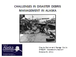
/
An artificial neural network application to produce debris An artificial neural network application to produce debris

An artificial neural network application to produce debris - PowerPoint Presentation

phoebe-click
phoebe-click . @phoebe-click
Follow
424 views
Uploaded On 2016-04-26

An artificial neural network application to produce debris - PPT Presentation

source areas of Barla Besparmak and Kapi Mountains NW Taurids Turkey Prepared by Lamiya ElSaedi 1 M C Tunusluoglu1 C Gokceoglu1 H Sonmez1 and H A Nefeslioglu2 ID: 294659

source debris continue area debris source area continue values probability study map stage slope distribution areas ann number aspect

Share:

Link:

Embed:

Download Presentation from below link

Download Presentation The PPT/PDF document "An artificial neural network application..." is the property of its rightful owner. Permission is granted to download and print the materials on this web site for personal, non-commercial use only, and to display it on your personal computer provided you do not modify the materials and that you retain all copyright notices contained in the materials. By downloading content from our website, you accept the terms of this agreement.


Presentation Transcript

Slide1

An artificial neural network application to produce debris source areas of Barla, Besparmak, and Kapi Mountains (NW Taurids, Turkey)

Prepared by :Lamiya El_Saedi

1

M. C. Tunusluoglu1, C. Gokceoglu1, H. Sonmez1, and H. A. Nefeslioglu2Slide2

1-Introduction:In engineering geologists and geomorphologists ANN is an attractive and important tool because has a high prediction capacity due to its high performance in the modeling of non-linear multivariate problems. One of these problems is to produce debris source maps because the debris materials are produced in mountainous regions with high slope gradients

and to access all debris source locations is almost impossible.

2Slide3

1-Introduction:These studies were applied in northern part of Turkey.The study is composed of two main stages such as compilation of the existing debris source area inventory map and

application of artificial neural network analyses between the existing landslide inventory map and the geological and geomorphological parameters.

3Slide4

2- General characteristics of the study area2.1 Geology The study area is located at the connection point of West Taurids and Middle Taurids2.2 Climate The precipitation data is very important for such type analyses.

4Slide5

5Slide6

3- Debris source inventory map6the study area has mainly high altitudes and steep slopes. These characteristics do not allow us access everywhere in the area for field observation. For this reason, an extensive aerial photo interpretation was carried out to extract the possible debris source areas using vertical black and white aerial photographs of medium scale (1:35 000), dated in 1956 and 1991Slide7

3- Debris source inventory map7to make an objective assessment for debris production potential of the lithological units, the following debris source intensity index (Eq. 1) is suggested by Tunusluoglu et al. (2007):

Where

DSI

i

is the debris source intensity of

lithology

I;

NPDS

i

is the number of pixels including debris source area of

lithology

I; and

AL

i

is the total area of

lithology

i

in the

whole study area.Slide8

3- Debris source inventory map8Slide9

4- Parameters contributing to debris generation9Statistical properties of each parameter were assessed into two groups such as: pixels representing debris source areas and

pixels representing free from debris source areas.Slide10

4- Parameters contributing to debris generation10Slide11

4- Parameters contributing to debris generation11Slide12

4- Parameters contributing to debris generation12Slide13

4- Parameters contributing to debris generation13Slide14

5- Application of ANN architecture to produce potential debris source area mapThe first stage in the application of the ANN architecture is the production of data matrix. While each

row data represents an individual case expressed using a terrain mapping unit (grid cell),

columnar data show the input and output variables in the data matrix. In this matrix, continuous variables (SPI, aspect, altitude, LS, plan curvature, profile curvature and slope) were normalized in the range of [0, 1].

Since the parameter of geology is a categorical data, it was expressed

in binary format with respect.

By considering 7 continuous variables and 15

lithological

units in binary format

total 22 independent variables were included in the ANN architecture.

Output variable of the analysis is also expressed in binary format with respect to

presence (1) and absence (0) of debris material

.

14Slide15

Continue stage 1:Multi-layer neural network (MNN) with back-propagation (BMNN) has been successfully used as a mapping and prediction tool in the engineering geology.The sigmoid function is preferred as the transfer function in this study.

The forward and backward stages are performed repeatedly until the neural network solution reaches the predefined threshold for the root mean square error (RMSE).

15Slide16

Continue stage 1:Number of training samplesIn this study using Kavzoglu (2001) proposed that the optimal number of training samples must be between [30 × numbers of input nodes ×(numbers of input nodes+1)] and [60 × numbers of input nodes × (numbers of input nodes+1)].

The number of dataset should be between 15 180 and 30 360. In this study, total 10 077 pixels are included by the debris source areas in the debris source inventory map.20% of this amount were selected randomly, and assigned as the test data set.

16Slide17

Continue stage 1:The initial weights, the initial weight range was randomly selected between −1.0 and 1.0.learning rate (α) and momentum coefficients (μ) plays important role on the time consuming during the training phase of ANN.

dynamic learning rate was preferred instead of constant unique value

17Slide18

Continue stage 1:Dynamic learning rate was introduced by using the heuristic:A multiplier is selected to increase or decrease the learning rate. If the sum of square errors at the current epoch exceed the previous value by more that a predefined value (typically 1.04), the learning rate parameter is decreased (typically by multiplying by 0.7), on the contrary,

If the error is less than the previous one learing rate is increased (typically by multiplying by 1.05)

according to the heuristic proposed by Negnevitsky (2002).A function for multiplier in the range of predefined ratio of the sum of square errors obtained current to previous epochs was preferred instead of constant value in the approach introduced in this study. The approach is explained in Fig. 5, and given by Eq. (6).

18Slide19

Continue stage 1:19Slide20

Continue stage 1:

20Slide21

Continue stage 1: Where m is multiplier, SSE is sum of square error,

α is learning rate.The

momentum coefficient was set to 0.95

21Slide22

Continue stage 1:Selection of the number of neurons is one of the most critical tasks in the ANN structure.In this study, the heuristic approach proposed by Kaastra and Boyd (1996) was employed

because this approach gives minimum number of hidden layers among the approaches proposed for the selection of the number of hidden layers. In this study

, the numbers of input and dataset are very large. As a result of the heuristic approach proposed by

Kaastra

and Boyd (1996),

total 5 neurons in one hidden layer were obtained for the model employed in this study (Fig. 6).

22Slide23

Continue stage 1:The ANN structures were trained by using combinationsof learning rates and the number of hidden neurons

23Slide24

Continue stage 1:24Slide25

Continue:The datasets were normalized between zero and 1 considering the maximum values of input variables. In this study, a computer code, namely ANNES written by Sonmez et al. (2006) was used to construct the ANN structure. The relation between the number of training cycles and the RMSE values of the models obtained by ANNES for each random data set are given in Fig. 7. During the training stages, total 40 000 training cycles were performed and the minimum RMSE values were obtained at approximately 10 000th cycle. At this cycle, the obtained minimum RMSE value is 0.22 for the second training set, while that of value is calculated as 0.064 again for the second test set (Fig. 7a).

Using the trained ANN model at 10 000th cycle for the second random sampling, the debris source area susceptibility map was produced and given in Fig. 8. Considering the receiver operating characteristic curves (ROC) and the area under curve (AUC) values, the more spatially effective map was achieved by using the second random sampling (Fig. 7b).

25Slide26

Continue:26Slide27

Continue:27Slide28

Continue:if slope aspect and orientation of bedding planes are same in the region, no debris generation occurs. However, this situationwas not detected by aerial-photo interpretations due to scale of the aerial photos and vegetation cover at some parts of the study area. For this reason, a structural adjustment for the debris source area susceptibility map is needed. Sinceit was observed that all debris generation occurs on the geomorphologic units of cuestas, it can be considered that all debris source areas mapped during field studies coincided with the geomorphologic units of cuestas

. Consequently, this situation constitutes the main assumption of the approach proposed for the structural adjustment for the susceptibility map of potential debris source area in this study

28Slide29

Continue:The second assumption is that theoretical probability distribution of slope aspect values of debris source areas is equal to the theoretical probability distribution of being a cuesta in the field. If Pq is the probability of being a cuesta, 1−Pq is the probability of not being a

cuesta. To calculate the adjusted probability (P d of being a debrissource area at a point in the field, 1−Pq (the probability of not being a cuesta

) is subtracted from the probability (Pd ) value of being a debris source area. Calculation of the value “1−Pq” (the probability of not being a

cuesta

) has

three main stages.

First stage is

the construction of the theoretical probability distribution of slope aspect values of debris source areas. However, due to the categorical nature of slope aspect values, a transformation is needed to obtain the continuous slope aspect distribution. For example, value of −1 in the slope aspect values does not mean orientation information. It means flat areas in the field.

Hence, this value should be excluded from the distribution. In addition, the value “0” and the value “360” in the slope aspect distribution are equal with respect to orientation information. So, the transition from “0” to “360” should be removed

(second stage)

.

29Slide30

Continue:For this purpose, the slope aspect values in the range of [0, 157] were summed with the value 360. The new distribution which shows almost an ideal theoretical normal distribution (Fig. 9) is obtained in the range of [165, 514]. The mean and the standard deviation values of this distribution are 337.32 and 42.59, respectively (Tunusluoglu et al., 2007). As a result, the probability density function of this distribution can be written as follows. f (x)=[1/42.59 p (2)] exp(−[1/(3628.04)(x−337.32)2]) (7)For the last stage, using Eq. (4), the probability values of being a cuesta

were calculated (the value “Pq ”). Then, to obtainthe probability values of not being a cuesta, these “Pq” values were subtracted from 1. To obtain the adjusted probability

(P0 d ) values of being a debris source area, the values “1−Pq” was subtracted from the probability values of debris source areas.

30Slide31

Continue:31 Finally, adjusted potential debris source area map is obtained (Fig. 10) by using the adjusted probability values. The adjusted map was not classified into subclasses and the map was given as continuous scale. However, to make a general assessment, it may be classified into three sub-classes such as low (0–0.4), moderate (0.4–0.6) and high (0.6–1). The percent areal extensions of low, moderate and high susceptibility classes are found as 93.3%, 3.0% and 3.7%, respectively.