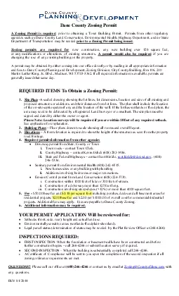
/
For more information regarding this booklet please contact:Zoning and For more information regarding this booklet please contact:Zoning and

For more information regarding this booklet please contact:Zoning and - PDF document

phoebe-click
phoebe-click . @phoebe-click
Follow
400 views
Uploaded On 2016-08-21

For more information regarding this booklet please contact:Zoning and - PPT Presentation

City of Winnipeg wwwwinnipegcappdJune 2009 The map identixFB01ed as Schedule A to this Bylaw is added as Schedule A at the end of the Airport Vicinity Acoustic ByLaw No 641994 and forms part ID: 453585

City Winnipeg www.winnipeg.ca/ppdJune 2009 The

Share:

Link:

Embed:

Download Presentation from below link

Download Pdf The PPT/PDF document "For more information regarding this book..." is the property of its rightful owner. Permission is granted to download and print the materials on this web site for personal, non-commercial use only, and to display it on your personal computer provided you do not modify the materials and that you retain all copyright notices contained in the materials. By downloading content from our website, you accept the terms of this agreement.


Presentation Transcript

For more information regarding this booklet please contact:Zoning and Permits BranchPH: 204-986-5140AX: 204-986-6347Plan Examination BranchAX: 204-986-3045or City of Winnipeg www.winnipeg.ca/ppdJune 2009 The map identified as Schedule A to this By-law is added as Schedule A at the end of the Airport Vicinity Acoustic By-Law No. 6419/94 and forms part of that By-law.Schedule A SUMMARY: Dwelling: A 3-bedroom bungalow Building location: NEF 33ining- Bedroom Bedroom Bedroom Room living Kitchen 1 2 3 Bathrm BsmtNo. of components 4 4 3 3 3 3 2Acoustic Insulation 34 29 38 38 38 28 26% Window to 9 6 8 8 6 1% Exterior wall to 87 43 108 126 57 60 40% Exterior door to 15 - - - - -APPROPRIATE COMPONENTS (Table 3.3.A.) 3(6)3 2(6)2 3(13)3 3(16)3 3(13)3 2(6)2 2Exterior walls (Table 3.3.B.) EW4 EW4 EW4 EW4 EW4 EW4 EW8Ceiling-roof (Table 3.3.C.) C2 C2 C2 C2 C2 C2 Exterior doors (Table 3.3.D.) D1-sd D1-sd AIF AdjustmentsLiving-Dining Room - AIF = 34 (4 components)AIF minus Transmitted Component AIF AIF (req’d) Sound Ceiling-roof +13 -22% Exterior wall +6 -19% Windows -4 +38% Doors Overall increase = Bedroom 2 - AIF = 38 (3 components) AIF minus Transmitted Component AIF AIF (req’d) Sound Ceiling-roof +9 -29% Exterior wall Windows -2 +20%Overall increase = From Table 3.1.C: AIF = 28.From Table 3.1.C.: AIF = 26.is necessary at this stage to calculate the percentages of the total window area, total exterior door area and the net exposed exterior wall area. (i.e. excluding window and door areas) to the total floor area for each room. % Window % Exterior wall % Exterior door Room area to total area to total area to total floor area floor area floor areaDining-living 19 Bedroom 1 6 Bedroom 2 8 Bedroom 3 8 Notes: (1) The window area includes the window in the front closet (2) The total door area is the are of the front and rear exterior (3) The total door area is the area of the rear exterior door To determine the appropriate build-components for this dwelling it is necessary to undertake calculations for the dining room, the living room the kitchen, the three bedrooms, the bathroom and the basement. Two features of the dwelling require special consideration, the living room and dining room form one large room and the rear exterior door is adjacent to the doorways of both Number of Components and Acoustic Insulation Factors:calculation is made for the entire area as one room. The components component: Exterior walls, measured from the back of the front closet to the rear door.otal number of components = 4. From Table 3.1.B: AIF = 34.are the window, exterior wall, ceiling-roof and rear exterior otal number of components = 4. From Table 3.1.C: AIF = 29.bedroom has three components — window, exterior wall and ceiling-Table 3.1.A: AIF = 38. 11Notes to Table 3.3.C.(1) C1 denotes 12.7 mm gypsum board, 75 mm (or thicker) insulation batts, flat roof joist and beam construction, built-up roofing. C2 denotes, 12.7 mm gypsum board, 75 mm (or thicker) insulation batts, typical wood roof truss with ventilated attic, sheathing and asphalt roofing. C3 denotes paint finish, 150 mm concrete slab, 50 mm (or thicker) rigid insulation, built-up roofing.(2) D signifies the addition of a second layer of 12.7 mm gypsum board. R signifies mounting the gypsum board on wood strap-(3) Wherever possible, ventilation openings to attic spaces should be in locations not directly exposed to aircraft noise.Notes to Table 3.3.D.(1) If the calculated percentage door area is not presented as a column heading, the nearest percentage column in the table (3) D1 denotes 44 mm hollow-core wood door (up to 20% of area glazed). D2 denotes 44 mm glass-fibre reinforced plastic door with foam or glass-fibre insulated core (up to 20% of area glazed). D3 denotes 35 mm solid slab wood door. D4 denotes 44 mm steel door with foam or glass-fibre insulated core. D5 denotes 44 mm solid slab door.(4) sd denotes storm door of wood or aluminium with openable glazed sections. The acoustic insulation factor values apply when Except as noted specifically above, doors shall not have inset glazing. Table 3.3.D.Forming Part of Article 3.3.1.Acoustic Insulation Factor for Exterior DoorsPercentage of Total Exterior Door Area to Total Floor Area of Room or SpaceType of Exterior Door 4 5 6.3 8 10 12.5 16 20 25 30 29 28 27 26 25 24 23 D2 33 32 31 30 29 28 27 D3 35 34 33 32 31 30 29 D4 36 35 34 33 32 31 30 D5 or D1 - sd 38 37 36 35 34 33 32 31 D2 - sd 41 40 39 38 37 36 35 34 D3 - sd 43 42 41 40 39 38 37 36 D4 - sd 44 43 42 41 40 39 38 37 D5 - sd 45 44 43 42 41 40 39 38 D3 - D3 48 47 46 45 44 43 42 41 D5 - D5 50 49 48 47 46 45 44 43 Column 13 4 5 6 7 8 Table 3.3.C.Forming Part of Article 3.3.1.Acoustical Insulation Factor for Roof-Ceiling Assemblies Roof-Ceiling Combination C1R or C1D C2 or C1DR C2DR Column 1 Notes to Table 3.3.B.(1) If the calculated percentage of wall area is not presented as a column heading, the near-The common structure of walls EW1 to EW5 is composed of 12.7 mm gypsum board, vapour barrier, and 38 x 89 mm studs with 50 mm (or thicker) mineral wool or glass fibre EW1 denotes exterior wall as in Note (2), plus sheathing, plus wood siding or metal siding EW2 denotes exterior wall as in Note (2), plus rigid insulation (25-50 mm), and wood siding or metal siding and fibre backer board. EW3 denotes simulated mansard with structure as in Note (2), plus sheathing, 38 x 89 mm framing, sheathing, and asphalt roofing material. EW4 denotes exterior wall as in Note (2), plus sheathing and 20 mm stucco. EW5 denotes exterior wall as in Note (2), plus sheathing, 25 mm air space, 100 mm brick veneer. EW6 denotes exterior wall composed of 12.7 mm gypsum board, rigid insulation (25-50 EW7 denotes exterior wall composed of 12.7 mm gypsum board, rigid insulation (25-50 EW8 denotes exterior wall composed of 12.7 mm gypsum board, rigid insulation (25-50 R signifies the mounting of the interior gypsum board on resilient clips.(5) An exterior wall conforming to rainscreen design principles and composed of 12.7 mm between the sheathing and the external finish has the same Table 3.3.8.Forming Part of Article 3.3.1.Acoustic Insulation Factor for Exterior Wall AssembliesPercentage of exterior wall area to total floor area of room or space Type of Exterior Wall 16 20 25 32 40 50 63 80 100 125 160 EW1 39 38 37 36 35 34 33 32 31 30 29 EW2 41 40 39 38 37 36 35 34 33 32 31 EW3 44 43 42 41 40 39 38 37 36 35 34 EW4 47 46 45 44 43 42 41 40 39 38 37 EW1R 48 47 46 45 44 43 42 41 40 39 38 EW2R 49 48 47 46 45 44 43 42 41 40 39 EW3R 50 49 48 47 46 45 44 43 42 41 40 EW5 55 54 53 52 51 50 49 48 47 46 45 EW4R 56 55 54 53 52 51 50 49 48 47 46 EW6 58 57 56 55 54 53 52 51 50 49 48 EW7 OR EW5R 59 58 57 56 55 54 53 52 51 50 49 EW8 63 62 61 60 59 58 57 56 55 54 53 Column 1 2 3 4 5 6 7 8 9 10 11 12 Notes to Table 3.3.A.(1) If the calculated percentage window area is not presented as a column heading, the insulation factor data listed in the table are for well-fitted weather stripped units that can be opened. The acoustic insulation factor values apply only when the windows are closed. For windows fixed and sealed to the frame, add 3 to the acoustic insulation If the interpane spacing or glass thickness for a specific double-glazed window is not acoustic insulation factor ratings for 9 mm and 12 mm glass are for laminated glass only; for solid glass subtract 2 from the acoustic insulation factor values listed in the If the interpane spacings for a specific triple-glazed window are not listed in the table, acoustic insulation factor data listed in the tables are for typical windows, but details of glass mounting, window seals, etc. may result in slightly different performance for some manufacturers’ products. If laboratory sound transmission loss data (conforming to ASTM test method E-90) are available, these may be used to calculate the For easy reference, glazing dimensions may be written in the form 2(100) to denote 2 Table 3.3.A.Forming Part of Article 3.3.1.Acoustic Insulation Factor for Various Types of Window GlazingInterpane spacing, mm Acoustic Insulation Factor Double Glazing Triple Glazing Single 3mm, 3mm, Window area as a percentage of Glazing 2mm & 3mm & 4mm & 3mm & 6mm & 3mm & 3mm & total floor area of room or space Thickness 2 mm 3mm 4mm 6mm 6mm 3mm 6mm 4 5 6 8 10 13 16 20 25 32 40 50 63 80 mm glass glass glass glass glass glass glass35 34 33 32 31 30 29 28 27 26 25 24 23 22 2 6 36 35 34 33 32 31 30 29 28 27 26 25 24 23 13 37 36 35 34 33 32 31 30 29 28 27 26 25 24 3 15 6 38 37 36 35 34 33 32 31 30 29 28 27 26 25 4,6 18 13 6 39 38 37 36 35 34 33 32 31 30 29 28 27 26 22 16 13 6 6 6, 6 0 39 38 37 36 35 34 33 32 31 30 29 28 27 9 28 20 16 13 13 6, 10 6, 641 40 39 38 37 36 35 34 33 32 31 30 29 28 35 25 20 16 16 6, 15 6, 1042 41 40 39 38 37 36 35 34 33 32 31 30 29 12 42 32 25 20 20 6, 20 6, 1543 42 41 40 39 38 37 36 35 34 33 32 31 30 50 40 32 25 24 6, 30 6, 2044 43 42 41 40 39 38 37 36 35 34 33 32 31 63 50 40 32 30 6, 40 6, 3045 44 43 42 41 40 39 38 37 36 35 34 33 32 80 63 50 40 37 6, 50 6, 4046 45 44 43 42 41 40 39 38 37 36 35 34 33 100 80 63 55 50 6, 65 6, 5047 46 45 44 43 42 41 40 39 38 37 36 35 34 125 100 80 75 70 6, 80 6, 6548 47 46 45 44 43 42 41 40 39 38 37 36 35 150 125 100 95 90 6, 100 6, 8049 48 47 46 45 44 43 42 41 40 39 38 37 36 150 125 110 100 6, 10050 49 48 47 46 45 44 43 42 41 40 39 38 37 150 135 125 Column 1 2 3 4 5 6 7 8 9 Table 3.1.D.and Other Rooms and Spaces not Included Under Tables 3.1.A. to 3.1.C.Number of Components Noise Contour at Building Site25 26 27 28 29 30 31 32 33 34 35 36 37 38 39 40 Over 4011 12 13 14 15 16 17 18 19 20 21 22 23 24 25 2814 15 16 17 18 19 20 21 22 23 24 25 26 27 28 3116 17 18 19 20 21 22 23 24 25 26 27 28 29 30 3317 18 19 20 21 22 23 24 25 26 27 28 29 30 31 3418 19 20 21 22 23 24 25 26 27 28 29 30 31 32 3519 20 21 22 23 24 25 26 27 28 29 30 31 32 33 36 Column 1 3 4 5 6 7 8 9 10 11 12 13 14 15 16 17 18Table 3.1.E.Total Number of Componentsfrom Tables 3.3.A. to 3.3.0. minus 2 3 4 5 6 ables 3.1.A. to 3.1.0. Percentage change in total transmitted sound power -30 -22 -18 -15-29 -22 -18 -15-28 -21 -17 -14-27 -20 -16 -13-25 -19 -15 -12-23 -17 -14 -10-20 -15 -12 -11-17 -12 -10 -8-12 -9 -7 -6-7 -5 -4 0 0 0 09 6 5 420 15 12 1033 25 20 1750 38 30 2572 54 43 36Column 1 3 4 5 6 Table 3.1.A. of Room or Space Envelope25262728293031323334353637383940Over 4025262728293031323334353637383940432930313233343536373839404142434631323334353637383940414243444548323334353637383940414243444546493334353637383940414243444546475034353637383940414243444546474851234567891011 1213141516Table 3.1.B. of Room or Space Envelope25262728293031323334353637383940Over 4021222324252627282930313233343538242526272829303132333435363738412627282930313233343536373839404327282930313233343536373839404144282930313233343536373839404142452930 31 32333435363738394041424346234567891011 12131415161718Table 3.1.C. of Room or Space Envelope25262728293031323334353637383940Over 401617181920212223242526272829 30 331920212223242526272829303132 33 362122232425262728293031323334 35 382223242526272829303132333435 36 392324252627282930313233343536 37 402425262728293031323334353637 38 4123456789101112131415161718Acoustic Insulation Factor for each Component of the Exterior Envelop of Rooms and Space Usedfor Sleeping 3.3. TYPICAL ASSEMBLIES3.3.1. Values for Building ComponentsTables 3.3.A. to 3.3.D. may be used to determine the acoustic insu-ation factor for some typical construction materials and assemblies, 3.1.3. Multiple Factors (1) If one or more components of the exterior envelope of a acoustic insulation factor that is more than the value required by Sentences 3.1.2.(1) to (4) the acoustic insulation for one or more other components of the exterior envelope be less than the value required by Sentences (a) the algebraic increase in transmitted sound power is (b) Table 3.1.E. is used to redistribute the acoustic insula-ion factor requirements for components whose acous-insulation factor deviates from the value required 3.2.1. Mechanical Ventilation (1) In on a site at which the noise contour value is 25 or more, dwelling units and ccupancy shall be ventilated with a mechanical ventilation system (a) has a minimum diameter of 150 mm, (b) is insulated, (c) has a regulating damper that does not conflict with the (d) conducts outside air to the (2) If the noise contour value at a building site is more than 30, the mechanical ventilation system required by Sentence (1) shall be designed and installed in such a way that an owner or occupant of a dwelling unit, or residential occupancy need not make changes to the structure or dimensional changes to the Design. In the application of Tables 3.1.A. to 3.1.E., the number components forming the exterior portion of a room or space envelope shall be the total of all the types of exterior elements or assemblies that form the room or space including windows, doors, etc. The component area shall be the combined area of those ele- (1) The building shall be designed and constructed so that the acoustic insulation factor for each component of the exterior envelope of every room or space used for sleeping shall not be less than the value derived from Table 3.1.A (2) The building shall be designed and constructed so that the acoustic insulation factor for each component of the exterior envelope of every living room, dining room, recreation room and all other rooms of a similar nature shall not be less than the value derived from Table 3.1.B (3) The building shall be designed and constructed so that the acoustic insulation factor for each component of the exterior envelope of every kitchen, bathroom, laundry room and all other rooms of a similar nature shall not be less than the value derived from Table 3.1.C. (4) The building shall be designed and constructed so that the acoustic insulation factor for each component of the exterior envelope of general office areas, reception areas, and all other rooms and spaces not included in Sentences (1) to (3) is not less than the value derived from Table 3.1.D. SECTION 1. GENERAL This document is based on the “AIRPORT VICINITY ACOUSTIC INSULATION BY-LAW”, 6419/94.SECTION 2. APPLICATION2.1. Scope. This By-Law applies to all new residential one-family, two-family and multi-family dwellings to be constructed, subject to acoustic insulation requirements, within an airport vicinity protection area as defined and outlined in the Zoning By-Law.2.2. Work. All work required by this By-law shall be carried out in accordance with the Manitoba Building Code, the Winnipeg Build-, and the Winnipeg Electrical By-law. The Designated Employee shall be responsible 2.4. Definitions. Unless otherwise expressly provided or unless the context requires, words and expressions in this By-law have the same meaning as the same words and expressions in the Manitoba Building Code and the Winnipeg Building By-law.Insulation Factor means a number that is used as a measure of the reduction in the level of aircraft noise provided by the assemblies forming the exterior envelope of a build-oise contour means the value of the noise exposure forecast or the noise exposure projection at a particular building site as shown on the map attached hereto and shown as Schedule A to this By-law Airport Vicinity PLANNING, PROPERTY ARTMENT