/
X-ray Diagnostics and Their Relationship to Magnetic Fields X-ray Diagnostics and Their Relationship to Magnetic Fields

X-ray Diagnostics and Their Relationship to Magnetic Fields - PowerPoint Presentation

phoebe-click
phoebe-click . @phoebe-click
Follow
414 views
Uploaded On 2016-06-08

X-ray Diagnostics and Their Relationship to Magnetic Fields - PPT Presentation

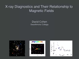
David Cohen Swarthmore College Xrays in massive stars are associated with their radiationdriven winds Power in these winds erg s 1 while the xray luminosity To account for the xrays only ID: 353575

Share:

Link:

Embed:

Download Presentation from below link

Download Presentation The PPT/PDF document "X-ray Diagnostics and Their Relationship..." is the property of its rightful owner. Permission is granted to download and print the materials on this web site for personal, non-commercial use only, and to display it on your personal computer provided you do not modify the materials and that you retain all copyright notices contained in the materials. By downloading content from our website, you accept the terms of this agreement.


Presentation Transcript

Slide1

X-ray Diagnostics and Their Relationship to Magnetic Fields

David CohenSwarthmore CollegeSlide2

X-rays in massive stars are associated with their radiation-driven windsSlide3

Power in these winds:

erg s

-1

while the x-ray luminosity

To account for the x-rays, only

one part in 10

-4

of the wind’s mechanical power is needed to heat the windSlide4

Three models for massive star x-ray emission1. Instability driven shocks

2. Magnetically channeled wind shocks3. Wind-wind interaction in close binariesSlide5

M 17: The Omega NebulaSlide6

CEN1AB - Kleinmann’s

Anonymous Star – is an O4+O4 binary system – with 1.8” separation Slide7

s

imulated Chandra grating spectrum

Line ratios

for location of the X-ray emitting plasma

Line

widths

for the plasma kinematicsSlide8

The

Chandra X-ray Observatory started taken the data yesterdaySlide9
Slide10
Slide11
Slide12
Slide13

The X-ray spectrum will tell us:

Line ratios for location of the X-ray emitting plasmaLine widths

for the plasma kinematicsSlide14

z

Pup

1

Ori C

Si XIII

Si XIV

Mg XI

Mg XII

H-like

/

He-like

ratio is temperature sensitiveSlide15

z

Pup

1

Ori C

Si XIII

Si XIV

Mg XI

Mg XII

1

Ori

C – is hotter

H/He > 1 in

1

Ori

C Slide16

Differential Emission Measure

(temperature distribution)

Wojdowski & Schulz (2005)

q

1

Ori

C is much hotterSlide17

1000 km s-1

Emission lines are significantly narrower, too

q

1

Ori C

(O7 V)

z

Pup

(O4 If)Slide18

Mg XII Ly-a in q

1 Ori C compared to instrumental profileSlide19

Ne X Ly-a in q

1 Ori C : cooler plasma, broader – some contribution from “standard” instability wind shocksSlide20

The X-ray properties of q1 Ori C can be understood in the context of its magnetic field and the magnetically channeled wind shock (MCWS) mechanismSlide21

Wade et al. 2008

Dipole magnetic field Slide22

Shore & Brown, 1990Slide23

MCWS: Babel & Montmerle 1997Slide24

Dynamical models (ud-Doula; Townsend): color scale shows emission measure in different temperature regimes

astro.swarthmore.edu/~cohen/presentations/MiMeS2/zeus-movie.aviSlide25

Looking at individual physical variables:Note that the hot, post-shock plasma:

has relatively low density, is concentrated near the tops of the largest closed-loop regions (~2Rstar),and is very slow moving (due to confinement)Slide26

temperature

emission measure

MHD

simulation summary

Channeled collision is close to

head-on:

D

v

> 1000

km s

-1

: T > 10

7

K

Gagné

et al. (2005)Slide27

Differential emission measure

(temperature distribution)

MHD simulation of 

1

Ori

C reproduces the observed differential emission measure

Wojdowski

& Schulz (2005)Slide28

There are Chandra observations at many different phasesSlide29

0.0

0.5

1.0

1.5

Simulation EM (10

56

cm

-3

)

0.0

0.1

0.2

0.3

0.4

θ

1

Ori C ACIS-I count rate (s

-1

)

0.0 0.2 0.4 0.6 0.8 1.0

Rotational phase (P=15.422 days)

Chandra

broadband count rate vs. rotational phase

Model from MHD simulationSlide30

0.0

0.5

1.0

1.5

Simulation EM (10

56

cm

-3

)

0.0

0.1

0.2

0.3

0.4

θ

1

Ori C ACIS-I count rate (s

-1

)

0.0 0.2 0.4 0.6 0.8 1.0

Rotational phase (P=15.422 days)

The star itself occults the hot plasma

in the magnetosphere

The closer the hot plasma is to the star, the deeper the dip in the x-ray light curveSlide31

0.0

0.5

1.0

1.5

Simulation EM (10

56

cm

-3

)

0.0

0.1

0.2

0.3

0.4

θ

1

Ori C ACIS-I count rate (s

-1

)

0.0 0.2 0.4 0.6 0.8 1.0

Rotational phase (P=15.422 days)

The star itself occults the hot plasma

in the magnetosphere

hot

plasma is

too far from

the

star in the simulation –

the

dip is not deep enoughSlide32

q1 Ori C column density (from x-ray absorption) vs. phase

equator-onpole-onSlide33

Emission measure

contour encloses T > 106 KSlide34

Helium-like species’ forbidden-to-intercombination

line ratios – f/i or z

/

(x+y

)

– provide information about the

location

of the hot plasma

Slide35

g.s. 1s

2

1

S

1s2s

3

S

1s2p

3

P

1s2p

1

P

resonance (w)

intercombination (x+y)

forbidden (z)

10-20 eV

1-2 keV

Helium-like ions (e.g. O

+6

, Ne

+8

, Mg

+10

, Si

+12

, S

+14

) – schematic energy level diagramSlide36

1s2s

3

S

1s2p

3

P

1s2p

1

P

resonance (w)

intercombination (x+y)

forbidden (z)

g.s. 1s

2

1

S

Ultraviolet light from the star’s photosphere drives

photoexcitation

out of the

3

S level

UVSlide37

1s2s

3

S

1s2p

3

P

1s2p

1

P

resonance (w)

intercombination (x+y)

forbidden (z)

g.s. 1s

2

1

S

Weakening the forbidden line and strengthening the

intercombination

line

UVSlide38

1s2s

3

S

1s2p

3

P

1s2p

1

P

resonance (w)

intercombination (x+y)

forbidden (z)

g.s. 1s

2

1

S

The

f/i

ratio is thus a diagnostic of the local UV mean intensity…

UVSlide39

1s2s

3

S

1s2p

3

P

1s2p

1

P

resonance (w)

intercombination (x+y)

forbidden (z)

g.s. 1s

2

1

S

…and thus the distance of the x-ray emitting plasma from the photosphere

UVSlide40

1 Ori CMg XISlide41

R

fir

=1.2 R*

R

fir

=4.0 R

*

R

fir

=2.1 R

*Slide42

He-like f/i

ratios and the x-ray light curve both indicate that the hot plasma is somewhat closer to the photosphere of q1

Ori C

than the MHD models predict. Slide43

So, in q1 Ori C, the X-rays tell us about the magnetospheric

conditions in several ways: High X-ray luminosityX-ray hardness (high plasma temperatures)Periodic variability (rotation and occultation)Narrow emission lines (confinement)f/i

ratios quantify locationSlide44

What about other magnetic massive stars? Slide45

What about confinement? Recall:

q

1

Ori

C:

h

*

~ 20 : decent confinementSlide46

What about confinement? Recall:

q

1

Ori

C:

h

*

~ 20 : decent confinement

z

Ori

:

h

*

~ 0.1 : poor confinement

s

Ori

E:

h

*

~ 10

7

: excellent confinementSlide47

q1 Ori C has a hard X-ray spectrum with narrow lines

…HD191612 and z Ori have soft X-ray spectra with broad linesFe XVII in z

Ori

-

v

inf

+

v

inf

l

oSlide48

1

Ori C

z

OriSlide49

t Sco does have a hard spectrum and narrow lines

Ne

Lya

compared to instrumental response: narrowSlide50

t Sco: closed loop region is near

the star…Slide51

t Sco: closed loop region is near the star……

f/i ratios tell us X-rays are far from the star (~3Rstar)

f

iSlide52

Do He-like f/i ratios provide evidence of hot plasma near the photospheres of O stars? Slide53

Do He-like f/i ratios provide evidence of hot plasma near the photospheres of O stars? No, I’m afraid they do

not. Slide54

z Pup S XV Chandra MEG

Features are very blended in most O stars: here, the three models are statistically indistinguishablelocations span 1.1 Rstar

to infinitySlide55

s Ori E (h* ~ 10

7: RRM+RFHD)Slide56

Chandra ACIS (low-resolution, CCD) spectrumSlide57

DEM derived from Chandra ACIS spectrumSlide58

DEM from RFHD modelingSlide59

Observed & theoretical DEMs agree wellSlide60

RFHD (Townsend, Owocki, & ud-Doula 2007, MNRAS, 382, 139 )

astro.swarthmore.edu/~cohen/presentations/MiMeS2/hav-rfhd-4p.aviSlide61

Conclusions

MCWS dynamical scenario explains q1 Ori C well…but, in detail, MHD models do not reproduce all the observational properties

Most other magnetic massive stars have X-ray emission that is different from

q

1

Ori

C

Some have soft X-ray spectra with broad lines

Closed field regions may not always be associated with the X-rays (

t

Sco

)

f/i

ratios, hard X-rays, variability in massive stars…

not

unique to magnetic field wind interaction