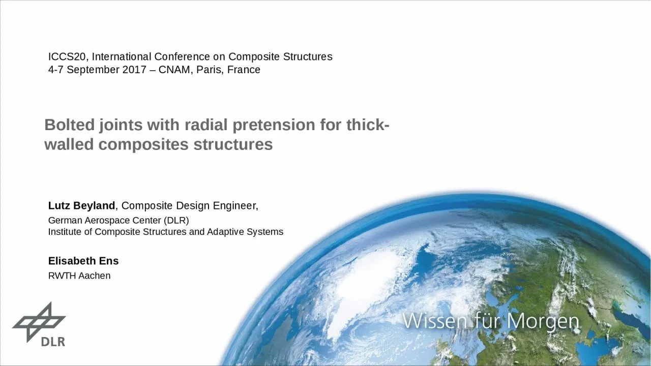
/
Bolted  joints with  radial pretension for thick-walled composites structures Bolted  joints with  radial pretension for thick-walled composites structures

Bolted joints with radial pretension for thick-walled composites structures - PowerPoint Presentation

samantha
samantha . @samantha
Follow
27 views
Uploaded On 2024-02-02

Bolted joints with radial pretension for thick-walled composites structures - PPT Presentation

Lutz Beyland Composite Design Engineer German Aerospace Center DLR Institute of Composite Structures and Adaptive Systems Elisabeth Ens RWTH Aachen ICCS20 International Conference on Composite Structures ID: 1043629

iccs20 beyland radial 2017dlr beyland iccs20 2017dlr radial pretension slide folie bolt hole bore load model bolted bearing composite

Share:

Link:

Embed:

Download Presentation from below link

Download Presentation The PPT/PDF document "Bolted joints with radial pretension f..." is the property of its rightful owner. Permission is granted to download and print the materials on this web site for personal, non-commercial use only, and to display it on your personal computer provided you do not modify the materials and that you retain all copyright notices contained in the materials. By downloading content from our website, you accept the terms of this agreement.


Presentation Transcript

1. Bolted joints with radial pretension for thick-walled composites structuresLutz Beyland, Composite Design Engineer,German Aerospace Center (DLR)Institute of Composite Structures and Adaptive SystemsElisabeth EnsRWTH AachenICCS20, International Conference on Composite Structures4-7 September 2017 – CNAM, Paris, France

2. > ICCS20 > Beyland > 05.09.2017DLR.de • Folie 2OutlineState of the art bolted joints in thick walled laminatesConcept of bolted joint with radial pretensionAnalytical approachFE-CalculationBearing testsConclusion and Outlook

3. > ICCS20 > Beyland > 05.09.2017DLR.de • Slide 3Bolted joints for thick laminates - state of the artFields of application for many decadesmulti-stage rockets for transportation of satellitesconnection of aircraft wing and fuselageroot connection of rotor blades of wind turbinesFailure modesTensionShear OutCleavageBearingPayload adapter Ariane 5 [DIEM]T-Bolt connection for rotor blades [HAU]

4. > ICCS20 > Beyland > 05.09.2017DLR.de • Slide 4Problems of state of the art bolted jointsJoint stiffness and wear depend on bolt-hole clearanceAvoiding big bolt-hole clearance leads toHigh effort for precise drilling of boreholeNeed for reaming / drilling of both joint parts in one processBig ClearancePPLow Stiffness, high wearPPHigh Stiffness, medium wearSmall / No ClearanceRadial PretensionPPVery high stiffness, low wear

5. > ICCS20 > Beyland > 05.09.2017DLR.de • Slide 5Concept of radial pretensionClamping bush overcomes clearance and creates a radial pretension between bolt and bore holeRadial pretension by axial tightening of inner and outer ringOuter ring of clamping bush is slatted >> Diameter increase of 1 mm possible2 - No Clearance3 - Radial Pretension1 - ClearanceInnerringOuterringBoltPlate with bore holeOuter ringInner ringOuter ringInnerringClamping bush [MÄDLER]

6. > ICCS20 > Beyland > 05.09.2017DLR.de • Slide 6Research topics on bolted joint with radial pretension Analytic modelto describe stress state around bore holeFE modelto validate mathematical model andfor detailed analysisBearing testsStatic and fatigue strength 

7. > ICCS20 > Beyland > 05.09.2017DLR.de • Slide 7Analytic approachPretension [Timoshenko]         Bolt load [Zhang]     Superposition

8. > ICCS20 > Beyland > 05.09.2017DLR.de • Slide 82D FE model - setupFE-Software: Ansys Workbench 18.1Boundary conditionsSymmetry at midplaneFixed support of disk‘s peripheral surfaceBolt load as distributed force on bolt’s peripheral surfaceRadial pretension by thermal expansion of boltFrictionless contact between bolt and holeMaterialLinear-elastic modelDisk: GFRP, quasi-isotropic stiffnessBolt: SteelFixedsupportBolt loadThermal expansionDiskBoltSymmetry

9. > ICCS20 > Beyland > 05.09.2017DLR.de • Slide 92D FE model - resultsRadial stressParameterVariableValueUnitRadius bore holea32,5mmOuter radius diskb800mmYoung‘s Modulus diskE27GPaPoisson's ratio diskν0,343-Pretensionpi270MPaRadial expansion (caused by pretension)u00,5mmBolt loadp28kN/mmUse case

10. > ICCS20 > Beyland > 05.09.2017DLR.de • Slide 10Comparison of analytical and FE model    Circum-ferential pathStresses at bore hole (circumferential path)σrad maximum difference: 2 MPaσtan maximum difference: 5 MPaConclusion: Analytical model is accurate for stresses at bolt hole

11. > ICCS20 > Beyland > 05.09.2017DLR.de • Slide 11Comparison of analytical and FE model    Radial pathStresses at bore hole (radial path)σrad maximum difference: 16 MPa (~7%)σtan maximum difference: 20 MPa (~17%)Conclusion: Analytical model is sufficient for stresses at whole disk

12. > ICCS20 > Beyland > 05.09.2017DLR.de • Slide 12Effect of friction on stress distribution – 2D-FEFriction strongly influences stress distributionCoefficient of friction µ between bolt and hole is not well knownLiterature [Cuntze] suggestsµ = 0,1 – 0,3>>> µ = 0,1 chosenNearSlidingStickingContact statusµ = 0  µ = 0,1  µ = 0,5      Circum-ferential path

13. > ICCS20 > Beyland > 05.09.2017DLR.de • Slide 13Effect of pretension on stress distribution – 2D-FEAmount of pretension significantly influences both radial and tangential stressHigh pretension avoids clearance under bolt load >> no tangential stress peak atMedium pretension results in minimum overall tangential and radial stresses SzenarioPretensionpi [MPa]Expansionu0 [mm]High pretension2700,5Medium pretension1350,25No pretension00    Circum-ferential path

14. > ICCS20 > Beyland > 05.09.2017DLR.de • Folie 14Bearing test setupSpecial 3-Point bearing test setupLaminate thickness t = 10…20 mmMaximum static load: F = 500 kNMaximum fatigue load: -50 kN < F < +200 kNSpecimen GFRP[+45 / -45 / 0 / 90]5sBoltd = 40 mmBore hole for fixationBearing failure 

15. > ICCS20 > Beyland > 05.09.2017DLR.de • Folie 15Clearance fit vs. radial pretensionClearance fitClamping bush for radial pretensionClearance = 0,1 mmRadial expansion u0 = 0,4…0,8 mm

16. > ICCS20 > Beyland > 05.09.2017DLR.de • Folie 16Results in bearing strength Bearing strength F… bolt load at failured… hole diametert… laminate thicknessStatic bearing strength with radial pretension -15% compared to clearance fitFatigue bearing strength with radial pretension +40% compared to clearance fitHigh pretension results in slightly higher fatigue strength 

17. > ICCS20 > Beyland > 05.09.2017DLR.de • Slide 17Conclusion and OutlookConclusionAnalytic model for bolted joints with radial pretension is found and validated by FE-calculation (neglecting friction and cleavage)Friction has a big impact especially on tangential stressesRadial pretension results in smooth distribution of stresses around the bore holeBearing tests with radial pretension show an increase in fatigue strength, but a decrease in static strengthOutlookDetailed understanding of bearing failure with radial pretensionPrediction of failure load from FE-calculation>>> failure criteria for bearingBearing tests with different pretensions>> evaluation of optimum pretensionBearing tests with combined radial and axial pretension

18. > ICCS20 > Beyland > 05.09.2017DLR.de • Slide 18MANY THANKS FOR YOUR ATTENTION !Lutz Beyland, Composite Design Engineer,German Aerospace Center (DLR), Institute of Composite Structures and Adaptive SystemsLilienthalplatz 7, 38108 Braunschweig, GermanyLutz.Beyland@DLR.deDO YOU HAVE ANY QUESTIONS ?

19. > ICCS20 > Beyland > 05.09.2017DLR.de • Slide 19References[DIEM]Diem, H.: Tragfähigkeit von Bolzenverbindungen in dickwandigen Faserverbundstrukturen; Dissertation; TU München; 19.2.2007[HAU]Hau, E.: Windkraftanlagen: Grundlagen, Technik, Einsatz, Wirtschaftlichkeit, Springer Berlin Heidelberg, ISBN 978-3-540-72150-5[MÄDLER]Mädler GmbH: Spannsätze COM-AS Bohrung 19 bis 100mm; http://www.maedler.de/product/1643/1621/spannsaetze-com-as-bohrung-19-bis-100mm; accessed on 30.8.2017[TIMOSHENKO]Timoshenko, S.: Theory of Elasticity; McGraw- Hill; 1934[ZHANG]Zhang, K.-D.; Ueng, C. E.: Stresses Around a Pin-loaded Hole in Orthotropic Plates; Journal of Composite Materials 18 (1984), No. 5, p. 432-446[CUNTZE]CUNTZE, R.; Das Versagensmoduskonzept, ein praktikables Auslegungswerkzeug bei neuen Leichtbauwerkstoffen“; Handout, Dresdner Leichtbausymposium, 7.-9. June 2001

20. > ICCS20 > Beyland > 05.09.2017DLR.de • Folie 20Anhang

21. > ICCS20 > Beyland > 05.09.2017DLR.de • Folie 21Lösungsraum für segmentierteRotorblätterJOULE IIIEnerconE126GamesaInnobladeIndeol / CENERModular Wind EnergyJOULE IIIConnection principleDetachableNon-DetachableBolting in longitudinal directionBolting in transversal directionBolting of pieces with a large overlapWelding of thermoplastsBonding of thermosetsT-boltsMetallicinsertsForm-fitForce-fitConnection tubesBolting of shear webSingle lapMulti lapSingle lapMulti lapMegawindJOULE IIIDEBRA-25T-boltsMetallicinsertsConnection tubesMulti lap

22. > ICCS20 > Beyland > 05.09.2017DLR.de • Folie 22Wo teilen?0.2100.30.40.50.60.70.8TransportationExtra mass = dynamic loadsSpar cap loadsSecondary loadsBig extra mass = extra costLittle spaceBoltingBonding

23. > ICCS20 > Beyland > 05.09.2017DLR.de • Folie 23Konzept „Stegverschraubung“Schnitt A-AWurzel-GurteTipGurteWurzel-StegTip-StegzxSchraube mit Mutter (ca. M36)Stegbuchse WurzelsegmentStegbuchse TipsegmentStegbuchse TipsegmentStegbuchse Wurzelsegmentca. 5mDetail ZyxWurzel-GurtWurzel-StegeTip-StegeTip-GurtyxSchnitt B-BzyDetail ZAABB

24. CAD-Modell „Stegverschraubung“ in Nordex-Rotorblatt NR58.5tipseitige VerschraubungwurzelseitigeVerschraubung> ICCS20 > Beyland > 05.09.2017DLR.de • Folie 24

25. > ICCS20 > Beyland > 05.09.2017DLR.de • Folie 25Segmentiertes Rotorblatt – Testpyramide (10-2016)

26. > ICCS20 > Beyland > 05.09.2017DLR.de • Folie 26Lochleibungstests BiLoKlebstoff>> verklebte Probe ohne FlanschSpannbuchse>> verspannte Probe>> gesteckte ProbeSpielpassung

27. > ICCS20 > Beyland > 05.09.2017DLR.de • Folie 27Rax-Buchse – Funktionsdemonstrator + Patentanmeldung