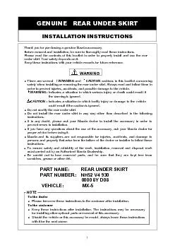
/
1. Remove the screws A (one each at left and right), torx bolts (2), s 1. Remove the screws A (one each at left and right), torx bolts (2), s

1. Remove the screws A (one each at left and right), torx bolts (2), s - PDF document

sherrill-nordquist
sherrill-nordquist . @sherrill-nordquist
Follow
382 views
Uploaded On 2015-11-24

1. Remove the screws A (one each at left and right), torx bolts (2), s - PPT Presentation

WARNING and Be careful not to drop the rear bumper when disengaging Rear bumpe r Bumper retaine r Rear bumpe r Screw A Screw B Screw B Torx bolt Fastene Fastene 1 Place the rear bumper onto a pro ID: 204128

WARNING and careful not

Share:

Link:

Embed:

Download Presentation from below link

Download Pdf The PPT/PDF document "1. Remove the screws A (one each at left..." is the property of its rightful owner. Permission is granted to download and print the materials on this web site for personal, non-commercial use only, and to display it on your personal computer provided you do not modify the materials and that you retain all copyright notices contained in the materials. By downloading content from our website, you accept the terms of this agreement.


Presentation Transcript

WARNING and 1. Remove the screws A (one each at left and right), torx bolts (2), screws B (one each at left and right) and the fasteners (one each at left and right). 2. Pull the front of the rear bumper toward the outside to disengage the rear bumper from the bumper retainer, and then remove the rear bumper from the vehicle. Be careful not to drop the rear bumper when disengaging Rear bumpe r Bumper retaine r Rear bumpe r Screw A Screw B Screw B Torx bolt Fastene Fastene 1. Place the rear bumper onto a protective sheet. 2. Use a marker pen or similar to make marks on the rear bumper in the marking-off positions ( ), and then check the hole positions. 3. Use a punch or similar to make marks in the centres of the marking-off positions ( ) on the rear bumper, and then follow the procedure below to make holes for installing the rear under skirt. [Making the holes] 8mm dia. (7 locations), 9mm dia. (6 locations) 8 mm dia. Holes: Use a 3 mm dia. bit and then a 8 mm dia. bit to make the holes gradually larger. 9 mm dia. holes: Use a 3 mm dia. and 9 mm dia. bit to make the holes gradually larger. Rear under skirt installation Install the U-nuts (Black) (4) to the rear bumper (hole positions Install the rear under skirt to the rear bumper. Be careful to avoid injuries when using tools such as the drill and saw. Wind tape around the drill bit to prevent any damage to the bumper and to stop the drill from protruding through. CAUTION 5. REAR UNDER SKIRT INSTALLATION Only make holes in the marking-off positions with a circle indicated ( ) Do not make holes in the marking-off positions that are only indicated by a cross. U-nut (Black) 9 Rear bumpe r Rear under skirt Back of the rear bumperscribed line bumper, and then drill rear bumper Front side of rear bumper 3. Apply thread sealer to the stud bolts, and then temporarily tighten them using the nuts (7 locations).4. Secure the underside of the rear under skirt using the bolts (with U- nuts (Black)) (2 locations) and the fasteners (2 locations).Tightening torqueBolts4.34.7 N48 kgf5. Secure the rear under skirt edge side to the U nut (Black) using Tightening torque4.7 N48 kgf6. Adjust the clearance between the rear bumper line and the rear under skirt by loosening the bolts and the nuts so that the clearance is consistently at approx. 2all around. Rear bumpe r Nut Fastene U- nut (Black) Rear under skirt Fastene Rear bumpe r U- nut (Black) Rear under skirt Rear bumperRear under skirt Rear bumperRear unde r 7. Moving from the center outward, fully tighten the nuts (7 locations) which were temporarily installed to the rear under skirt.Tightening torqueNuts1.8 N29.0 kgf1. After installing the rear under skirt, install the removed components by carrying out the procedure in "4. PART REMOVAL" in reverse.Screw A Tightening torque1.01.5 N{1115 kgfScrew B Tightening torque1.01.5 N{1115 kgfTorx bolt Tightening torque7.9110 kgfConnect the negative battery cable. 7. OPERATION CHECK 6. PART INSTALLATION Before starting the engine, make sure nobody is in front or back of the vehicle, or in the engine compartment If the vehicle were to move suddenly it could cause a serious accident. Do not start the engine in a place such as a garage or other location with poor air ventilation. Otherwise, poisoning or asphyxiation could result from accumulation of exhaust gas Disconnecting the battery causes the DSC indicator light to become inoperable.At this point, the DSC OFF indicator light flashes and the TCS/DSC indicator light is illuminated. To restore the DSC to an operable condition, perform the following procedures:Turn the ignition switch to the ON position.Turn the steering wheel completely to the right and then completely to the left.Verify that the DSC OFF indicator light goes out.Turn the ignition switch off and then turn it to the ON position again.Verify that the TCS/DSC indicator light goes out.If the TCS/DSC or DSC OFF indicator lights do not go out after turning the ignition switch to the ONposition, consult your Mazda dealer. When the battery is disconnected, the windows will not fully open and close automatically.Perform the following procedure to resume operation:Turn the ignition switch to the ON position.Press the switch and fully open the window.Pull up the switch and continue holding for about 2 seconds to fully close the window. Rear bumpe r Nut Rear bumpe r Screw A Screw B Screw B Torx bolt Fastene Fastene REAR UNDER SKIRT 0000 8Y D08 Inspection after installationInspect the installed / reinstalled parts for the following items.㧔٤㧕 Inspection PartsClearance/FitInstallation / Engagement Operation check Rear under skirt ٤٤٤ Trunk end trim ٤٤٤ Rear end trim ٤٤٤ Trunk side trim ٤٤٤ Rear combination lamp ٤٤٤٤ Rear bumper ٤٤٤ Power window ٤ Battery ٤٤ Important check items Inspect the installed / reinstalled parts for the following items.Page No. Part name Tightening torque Check and write the tightening torquePerson in charge Rear under skirt installation Step 4, 5(7 page) m N Rear under skirt installation Step 7(8 page) m N Rear bumper installation Step 1(8 page) Screw A Screw B Torx bolt Installation inspection sheet for rear under skirtDate , , VIN. ApprovedCheckedPerson in charge The term of validity for this sheet: 12 months