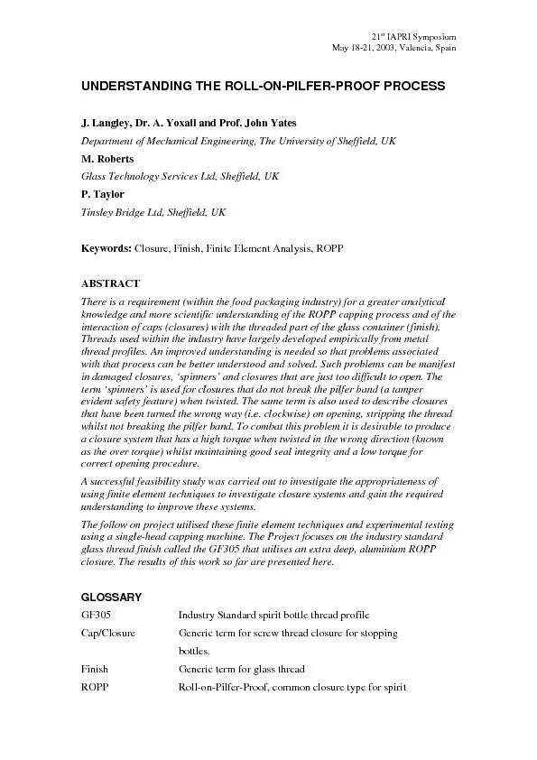
/
21st IAPRI Symposium May 18-21, 2003, Valencia, Spain UNDERSTANDING TH 21st IAPRI Symposium May 18-21, 2003, Valencia, Spain UNDERSTANDING TH

21st IAPRI Symposium May 18-21, 2003, Valencia, Spain UNDERSTANDING TH - PDF document

sherrill-nordquist
sherrill-nordquist . @sherrill-nordquist
Follow
384 views
Uploaded On 2016-07-09

21st IAPRI Symposium May 18-21, 2003, Valencia, Spain UNDERSTANDING TH - PPT Presentation

Understanding The ROPP Process Joseph Langley The University of Sheffield Sheffield UK bottles Waddingliner Material insert in the top of the closure to create a tight seal between glass and clos ID: 397426

Understanding The ROPP Process Joseph

Share:

Link:

Embed:

Download Presentation from below link

Download Pdf The PPT/PDF document "21st IAPRI Symposium May 18-21, 2003, Va..." is the property of its rightful owner. Permission is granted to download and print the materials on this web site for personal, non-commercial use only, and to display it on your personal computer provided you do not modify the materials and that you retain all copyright notices contained in the materials. By downloading content from our website, you accept the terms of this agreement.


Presentation Transcript

LANЅ؇ࠂNJAos,eЋEphh܈Y‡ALL܈A∣ଐer à £nd YATES܈ऊhn A⤣ᔢab∌ࠫromà ¨hef⬕e∖࠭a∢amà ®nᔩerକု࠰eଌarch Arᐎᔩeà ±Sâ´®RA)ࠣထ hတpᄒላhuraᜋhuᜣᐗu㐒4448/ Thiଈdoᐳment iଈthe authoገdeposited ⤌ጋion. You aጌ adviଌd to ᐊnsult the publi଎eጵଈveጋion if you wi଎ to ᐕte fጊm it. ጔihJYeGNsdGEYJpA LȃGLEY, ऊseph, YOXȁL, È¢aଐeገand YATÔ¨, ऊhn ㄛ003㈗ Undeጋtanding the ጊllᨊnᨍilfeጚpጊof proᐌଋ. In: 21ଐ IȺRI Sympoକum, Valenᐕa, May 18ᨛ1. .ptgEJoe܋ ANsEG༔YGstphJ/g ⠌e http://଎uጣ.଎u.aᐗu㐒infoጬation.html ᤌGᄑJGhNs- hh 2sLAJdGEYJ,gs9GYG E/es7E/eJdG http://଎uጣ.଎u.aᐗuk LANЅ؇ࠂNJAos,eЋEphh܈Y‡ALL܈A∣ଐer à £nd YATES܈ऊhn A⤣ᔢab∌ࠫromà ¨hef⬕e∖࠭a∢amà ®nᔩerକု࠰eଌarch Arᐎᔩeà ±Sâ´®RA)ࠣထ hတpᄒላhuraᜋhuᜣᐗu㐒4448/ Thiଈdoᐳment iଈthe authoገdeposited ⤌ጋion. You aጌ adviଌd to ᐊnsult the publi଎eጵଈveጋion if you wi଎ to ᐕte fጊm it. ጔihJYeGNsdGEYJpA LȃGLEY, ऊseph, YOXȁL, È¢aଐeገand YATÔ¨, ऊhn ㄛ003㈗ Undeጋtanding the ጊllᨊnᨍilfeጚpጊof proᐌଋ. In: 21ଐ IȺRI Sympoକum, Valenᐕa, May 18ᨛ1. .ptgEJoe܋ ANsEG༔YGstphJ/g ⠌e http://଎uጣ.଎u.aᐗu㐒infoጬation.html ᤌGᄑJGhNs- hh 2sLAJdGEYJ,gs9GYG E/es7E/eJdG http://଎uጣ.଎u.aᐗuk 21st IAPRI Symposium May 18-21, 2003, Valencia, Spain UNDERSTANDING THE ROLL-ON-PILFER-PROOF PROCESS J. Langley, Dr. A. Yoxall and Prof. John Yates Department of Mechanical Engineering, The University of Sheffield, UK M. Roberts Glass Technology Services Ltd, Sheffield, UK P. Taylor Tinsley Bridge Ltd, Sheffield, UK Keywords: Closure, Finish, Finite Element Analysis, ROPP ABSTRACTThere is a requirement (within the food packaging industry) for a greater analytical knowledge and more scientific understanding of the ROPP capping process and of the interaction of caps (closures) with the threaded part of the glass container (finish). Threads used within the industry have largely developed empirically from metal thread profiles. An improved understanding is needed so that problems associated with that process can be better understood and solved. Such problems can be manifest in damaged closures, ‘spinners’ and closures that are just too difficult to open. The term ‘spinners’ is used for closures that do not break the pilfer band (a tamper evident safety feature) when twisted. The same term is also used to describe closures that have been turned the wrong way (i.e. clockwise) on opening, stripping the thread whilst not breaking the pilfer band. To combat this problem it is desirable to produce a closure system that has a high torque when twisted in the wrong direction (known as the over torque) whilst maintaining good seal integrity and a low torque for correct opening procedure. A successful feasibility study was carried out to investigate the appropriateness of using finite element techniques to investigate closure systems and gain the required understanding to improve these systems. The follow on project utilised these finite element techniques and experimental testing using a single-head capping machine. The Project focuses on the industry standard glass thread finish called the GF305 that utilises an extra deep, aluminium ROPP closure. The results of this work so far are presented here. GLOSSARY GF305 Industry Standard spirit bottle thread profile Cap/Closure Generic term for screw thread closure for stopping bottles. Finish Generic term for glass thread ROPP Roll-on-Pilfer-Proof, common closure type for spirit Understanding The ROPP Process Joseph Langley, The University of Sheffield, Sheffield, UK bottles. Wadding/liner Material insert in the top of the closure to create a tight seal between glass and closure. EPE A type of linear material Wood pulp A type of linear material Over torque Torque required to turn the closure the wrong way and strip the thread Slip torque Torque required in opening the closure to make the initial movement or the very first slip Bridge torque Torque required in opening the closure to break the pilfer bridges between cap and pilfer band INTRODUCTION The overall aim of this research is to maximise the over torque and minimise the slip and bridge torques whilst maintaining a sufficient seal that will survived the rigors of transport and a number of re-applications after the initial opening. A feasibility study (references 1 & 2) demonstrated that finite element analysis (FEA) could be used to assess why closures behave in certain ways and hence assess the openability of the closures. The use of FEA also reduces the need for on-line testing, removing the cost and risks associated with producing new designs and/or set-up procedures through trial and error. The initial FE model (Figure 1) developed in this feasibility study performed well but several assumptions and simplifications were made to reduce the complexity of the model that also reduced the accuracy of the model: Geometric simplifications - Simple cap geometry that didn’t include the pilfer band or ID groove - Simple glass thread geometry Material property simplifications - Linear elastic liner material properties - Linear elastic cap material properties Simplified boundary conditions - No capping head pressure - No pilfer rollers It was necessary to improve the FEA models and at the same time to develop a series of physical test on the single head capping machine that could be used to both gain information to input to the FEA models and validate them. The liner material properties were improved and the FEA models of these material properties were rigorously tested as described in the work published by A. Yoxall et al (3). Further improvements to the FEA models have been carried out and now the Understanding The ROPP Process Joseph Langley, The University of Sheffield, Sheffield, UK FEA models and experimental tests are producing data that is leading to the desired understanding and knowledge. This paper deals with the improvements made to the FEA model, the FEA modelling strategy and the physical testing strategy. The parameters that have been examined so far include the affects of the capping head pressure, the affects of the roller pressure, the affects of whiskey on the glass sealing surface prior to capping, the affects of closures sourced from various cap manufactures and a start has been made on the affects of the pilfer bridges and pilfer band. The parameters surrounding the pilfer band and bridges and surrounding the glass geometry have yet to be fully investigated. CAPPING PROCESS The capping process for ROPP closures is a high-speed event. A typical production line will have a capping-head (Figure 2) lowered automatically over a bottle and closure applying a pressure that creates a seal between glass and liner material. As the capping-head rotates, a spring pivot system causes the rollers to move inwards. The rollers engage with the closure and finish and start to form the ROPP thread profile using the glass profile as a mandrill. The capping-head is calibrated to provide a load on the closure of 120N. On a typical high-speed production line 300 to 400 bottles are capped every minute. PHYSICAL TESTING The physical testing centres on a single-head capping machine. For all tests there was a general standard format. This consisted of photographing the closures before application (Figure 3a), recording the capping head pressure, roller pressure for all four rollers and photographing the closures after application (Figure 3b). Videos of the capping and opening processes were also taken. These enabled detailed examination of such things as the behaviour of the rollers and breaking of the pilfer bridges on opening. At least 50 bottles were tested for each parameter change. Forty of these were opened and the two opening torques; slip, bridge and the over torque were recorded (Figure 4. For confidentially reason the labels on the bottles have been blacked out.). These forty bottles were used for each parameter change to eliminate any slight variation in bottle geometry. The closures of remaining ten bottles that were capped for each parameter were cut from the bottles just below the closure and set in resin. These samples were then sectioned to allow examination of the closure and finish after application and before opening (Figure 5). Other physical testing was carried out that was pertinent to each individual parameter change. For example, an experiment was devised to test the sealing qualities of various capping head pressures over time (Figure 6. For confidentially reason the labels on the bottles have been blacked out.). Understanding The ROPP Process Joseph Langley, The University of Sheffield, Sheffield, UK There was also extensive experimental work carried out to establish the non-linear material properties of the liner material. FEA MODELLING The latest 3D finite element model consists of an industry standard GF305 thread finish geometry modelled as a rigid body (Figure 7) interfacing with the aluminium closure (Figure 8) meshed in 3D hexagonal brick elements to allow contact with both the glass on the inside and the rollers on the outside and the liner material meshed in a similar manner for similar reasons. The four rollers, two thread and two pilfer, are modelled as rigid bodies (Figure 9). The geometry for the rollers was obtained by measuring the dimensions of real capping-head rollers using a shadowgraph. There were also a series of smaller models in 3D and 2D. The 3D models consisted of just the liner material, sealing surface and top surface of the cap, just the top half of the closure looking at the threaded region and just the bottom half of the closure looking at the pilfer band region. The 2D models were both vertical (Figure 10) and horizontal sections through the closure. The parametric changes carried out on the capping machine were modelled and investigated using a combination of all these models. The FEA models have been developed for solving using the MARC finite element programme. MARC was chosen as it has good non-linear material routines and handles large deformation and contact relatively easily. The simple 2D models contain approximately 150 elements while the largest 3D model contains 22,000 elements. The largest 3D model takes a significant run time. RESULTS AND DISCUSSION Physical tests and FEA were analysed together in order to produce some degree of validation. The data gathered from all sources show that the capping head pressure does affect the sealing ability of the closure but reduction in capping head pressure from the industry standard of 120N to 60N does not affect the sealing quality to the order of causing leakage. The roller pressure also affects the sealing qualities of the closure system by increasing the compression of the liner and contact between glass and liner. An increase in roller pressure causes more compression and contact. Increasing the roller pressure also creates a more highly defined thread form and pilfer tuck under. However, the opening torque data does not show any correlation between roller pressure and opening torque suggesting that the roller pressure itself does not directly affect the openability of this closure system. One thing to note for both the capping head pressure and the roller pressure is that increased compression of the liner does increase the slip torque but not enough to raise it above the bridge torque which still remains the higher of the opening torque. As far as the whiskey on the sealing surface goes there was a suggestion that whiskey on the sealing surface did increase the slip torque and the over torque. However, the Understanding The ROPP Process Joseph Langley, The University of Sheffield, Sheffield, UK sample population for this test was very small and there will need to be further analysis of this before any real conclusions can be drawn including some particle scale surface analysis of the glass sealing surface after capping. As for the type of closure, for confidentially reasons it is only permissible to say at this point in time that there was a significant difference in the opening torques of the closures. It has yet to be determined as to the cause of this. It may not be the manufacturers. It is possible that the type of lacquer used may be the factor that is having such a great affect. Parametric changes that are in the process of being analysed include the rolling sequence and some of the pilfer region parameters. The rolling sequence refers to a variation on the current industry method of rolling thread and pilfer tuck under at the same time. This variation rolls the thread first and then rolls the pilfer tuck under after the thread has been rolled. Initial analyse of this parameter suggests that this reduces the opening torques. With the current industry method of rolling the thread and pilfer at the same time, it was observed that the thread rollers caused ‘thread pull-out’, a phenomena in which the cap material is pulled out of the first thread form in order to form the second thread. (Figure 11) The modified rolling sequence of rolling thread first and pilfer after the thread, demonstrated no ‘thread pull-out’ resulting in two well defined threads. CONCLUSIONS The main conclusions that can be drawn from the work so far is that the FEA model improvements on the feasibility study have produced a series of FEA models that have proved to give very useful information and a significantly greater understanding of the ROPP capping process. The use of FEA to investigate the problems associated with these closure systems is an innovation in two ways. It is an innovative use of FEA and also an innovation for the glass industry that has never used such tools before. It will prove to optimise the closure system and provide a tool that can be used for future re-design of such closure systems. It has shown a great inter-dependence of parameters, in that one small parametric change can lead to significant knock on affects in other areas of the system. This has meant that any conclusions drawn at this time may be temporary in that they may well change as the remaining parameters are investigated. However, what can be said with confidence is that the capping head pressure doesn’t have any great affect on leakage up to a value of half the capping head pressure that is current industry standard. It can also be said that the roller parameter directly affects the sealing qualities of the closure systems, increasing the sealing affects caused by the capping head pressure alone. This is shown in figure 12. It has also been demonstrated in both physical testing and FEA that rolling the thread first and forming the pilfer band after the thread, stops ‘thread pull-out’ occurring. Understanding The ROPP Process Joseph Langley, The University of Sheffield, Sheffield, UK FUTURE WORK With the development of this experimental and finite element testing strategy that has been rigorously tested and validated, the process of looking at individual parameters within the capping process and studying their affects on the performance of the closure system can continue. There is still much investigation into the various aspects of the pilfer band, pilfer bridges and glass finish dimensions that has to be done. With regard to the pilfer region, this is considered very important as the bridge torque is currently the highest of the slip and bridge opening torques that need to be reduced in order to make the closure more easily openable. With regard to the glass finish dimensions, an experimental plan and trial test has been carried out to look at rapid prototyping of glass thread finish design in order to physically test various changes to glass dimensions quickly, thoroughly and cheaply. This is all work that has recently begun. Anyone interested in joining this project should contact Dr. A. Yoxall, The University of Sheffield, Department of Mechanical Engineering, at the Engineered Packaging Research Group. Contact details at the end of this paper. ACKNOWLEDGEMENTS The authors would like to thank The Engineering and Physical Sciences Research Council (EPSRC), The White Rose Faraday Packaging Initiative in Leeds, British Glass and Glass Technology Services, (GTS). REFERENCES 1. Yoxall, A. & Haake, S. 2000, Numerical Simulation of interaction between a threaded glass container and a screw cap. Glass Technology. Vol 41/1 2. Yoxall, A. 2002, A numerical simulation of the roll-on-pilfer-proof process on a GF305 Thread. Glass Technology. Vol 43/3 3. Yoxall, A. & Langley, J. 2002, A Numerical Model of Closure Liner Materials. Glass Technology. Vol 44/6 4. Dragoni, E. 1994, Effect of thread pitch and frictional coefficient on the stress concentration in metric nut-bolt connections. Journal of Offshore Mechanics and Arctic Engineering. Vol. 116/21. 5. Kenny, B. & Patterson, E.A. 1989, The distribution of load and stress in the threads of fasteners-a review. Journal of Mechanical Behaviour of Materials. Vol. 2, 1-2. 6. Brennnan, F.P. & Dover, W.D. 1995, Stress intensity factors for threaded connections. Engineering Fracture Mechanics. Vol. 50/4; 545-567. 7. Lochegnies, D., Marion C., Carpentier E., & Oudin J., 1996, Finite element contributions to glass manufacturing, control and optimisation. Part 2. Blowing, pressing and centrifuging hollow items. Glass Technology. Vol. 27/5; 169-174. 8. Murnane, R.A. & Moreland, N.J. 1988, Ceramic Engineering Science Proceedings. Vol. 9/3-4:192-202. 9. British Glass Glass Container Finishes. TEC 3 Manual. Understanding The ROPP Process Joseph Langley, The University of Sheffield, Sheffield, UK Figure 1: a picture showing the feasibility model part way though its process. Leading roller Trailing roller First pass Second pass Understanding The ROPP Process Joseph Langley, The University of Sheffield, Sheffield, UK Figure 2: a picture showing the capping head machine Figures 3a and 3b: showing closure before and after application respectively Capping Head Thread Rollers Pilfer Band Rollers Bottle Cap Understanding The ROPP Process Joseph Langley, The University of Sheffield, Sheffield, UK Figure 4: a view of the torque testing machine in action Figure 5: a view of one of the sections of the closure system. Understanding The ROPP Process Joseph Langley, The University of Sheffield, Sheffield, UK Figure 6: A view of one of the tests for the capping head pressure parameter Figure 7: a picture showing the drawing of the industry standard GF305 thread finish used in the FEA modelling and modelled as a rigid body. Sealing surface Start of thread Thread run out Bead (Pilfer band is tucked under) Understanding The ROPP Process Joseph Langley, The University of Sheffield, Sheffield, UK Figure 8: a view of the 3D cap mesh. Note the mesh refinement around the pilfer bridges. Figure 9: a schematic of the full 3D model. Understanding The ROPP Process Joseph Langley, The University of Sheffield, Sheffield, UK Figure 10: a picture showing plastic strain in the cap in a 2D model of a vertical section through the closure. There are symmetry constraints applied at the left hand side of the model. Figure 11: This diagram shows a 2D FEA model demonstrating ‘thread pull-out’ Understanding The ROPP Process Joseph Langley, The University of Sheffield, Sheffield, UK Figure 12: This diagram shows a 2D FEA model demonstrating the extra sealing affects caused by the thread roller penetration The cap is forced downwards and inwards due to the roller pressure. This has the affect of increasing the degree of contact between liner and glass sealing surface at this point.