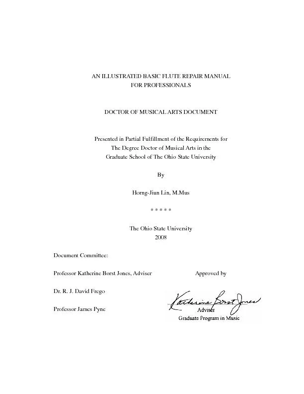
/
AN ILLUSTRATED BASIC FLUTE REPAIR MANUAL  FOR PROFESSIONALS  DOCTOR OF AN ILLUSTRATED BASIC FLUTE REPAIR MANUAL  FOR PROFESSIONALS  DOCTOR OF

AN ILLUSTRATED BASIC FLUTE REPAIR MANUAL FOR PROFESSIONALS DOCTOR OF - PDF document

sherrill-nordquist
sherrill-nordquist . @sherrill-nordquist
Follow
481 views
Uploaded On 2016-06-05

AN ILLUSTRATED BASIC FLUTE REPAIR MANUAL FOR PROFESSIONALS DOCTOR OF - PPT Presentation

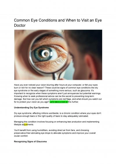
Copyright by HorngJiun Lin 2008 ABSTRACT repair manual for the modern Boehm and Br ID: 350258

Copyright

Share:

Link:

Embed:

Download Presentation from below link

Download Pdf The PPT/PDF document "AN ILLUSTRATED BASIC FLUTE REPAIR MANUAL..." is the property of its rightful owner. Permission is granted to download and print the materials on this web site for personal, non-commercial use only, and to display it on your personal computer provided you do not modify the materials and that you retain all copyright notices contained in the materials. By downloading content from our website, you accept the terms of this agreement.


Presentation Transcript

AN ILLUSTRATED BASIC FLUTE REPAIR MANUAL FOR PROFESSIONALS DOCTOR OF MUSICAL ARTS DOCUMENT Presented in Partial Fulfillment of the Requirements for The Degree Doctor of Musical Arts in the Graduate School of The Ohio State University * * * * * The Ohio State University Document Committee: Professor Katherine Borst Jones, Adviser Approved by Dr. R. J. David Frego Professor James Pyne Copyright by Horng-Jiun Lin 2008 ABSTRACT repair manual for the modern Boehm and Brögger flute mechanisms. Written for college professors and students, as opposed to d document offers step-by-step procedures to guide readers through standard repairs and maintenance. All chapters use four-color illustrations and offer practical repair techniques in a tight sequential order. Easy, sequential instructions in this manual minimize the complexity of basic flute mechanism repairs. Brief textual explanations accompany hundreds of close-up photos that take readers from the gathering of simple tools and supplies to the sophisticated rformed by the professional technician. This manual offers literacy on two levels: the brquality of images. This manual takes professors, students and flute aficionados to a whole new level of flute understanding and appreciation. ii Evolutionary aspects of the modern flute mechanism are included. Building a ing and prolonged efforts of flute makers of the past and their unique contributions to the making of the modern flute mechanism, as we know it today. Such a profound appreciation of flute development helps flutists see the extraordinary relationship between the mechanics and the fine art of making music. iii Dedicated to Father Robert Massé iv ACKNOWLEDGMENTS I wish to express my sincere gratitude and appreciation to my adviser, Professor process of this document. I have learned a lot from her during the six years at The Ohio State University. I also wish to sincerely thank my document committee Dr. R. J. David Frego, Professor Robert Sorton and Professor James Pyne, for their tive advice for the contents of this document. I am also grateful to Dr. Patrick Woliver, for his support and advice as the Graduate Studies Chair. I would like to acknowledge my indebtedness to two Taiwanese flute makers, Mr. Geoffrey Guo and Mr. Cheng-Rong Wang, for ng, wonderful ideas ques. My gratitude also goes to Dr. Jo-Ann Triner, for her expertise on document writing, her insightful opinions on this document, and her assistance as my English tutor. I v , former Finishing Department Manager ofFlute Company, for reviewing this document and providing constructive advice and suggestions. I wish to especially thank Father Robert Massé, my first flute teacher, for taking me as the youngest student during my Secondary school study. His love encouragement continue to help me. I will forever be grateful to my parents and siblings for their unconditional love and understanding. I also owe a great debt to my parents-in-law, for their endless words of encouragement and prayers. In addition, my heartfelt gratitude goes to my wonderful family: my wife and the photographer of this document, Vivian, for her love, understanding, support, encouragement and marriage; and my two adorable sons, Austin and Justin, for their cute personalities that cheer my heart every day. Finally, my deepest thankfulness goes to my Heavenly Father, for His endless love, blessings and promises. This document cwisdom He granted me. vi VITA October 6, 1973…………………………………Born----Taichung, Taiwan May, 2002……………………………………….B.M., Flute Performance, The Boston Conservatory, Boston, Massachusetts June, 2004……………………………………….M.M., Flute Performance, The Ohio State University, Columbus, Ohio 2004—Present…………………………………..Graduate Administrative Associate The Ohio State University, Columbus, Ohio FIELDS OF STUDY Major Field: Music in Flute Performance vii TABLE OF CONTENTS PageAcknowledgements Vita Chapters 1. A Concise Evolution of the Modern Flute Mechanism……………………….. The Boehm Flute Mechanism…………………………………………… Boehm’s 1831 Flute……………………………………………………… Boehm’s 1832 Flute……………………………………………………… Boehm’s 1847 Flute……………………………………………………… The Briccialdi B Flat Thumb Lever on the Boehm Flute Mechanism…... Variations of the Boehm Flute Mechanism on Modern Flutes………....... Brögger Flute Mechanism………………………………………….......... Brannen Brögger Mekanik……………………………………………..... Major Changes from the Boehm Systemto the Brögger Mekanik……… Miyazawa Brögger Major Changes from the Brögger Mekanik to the Brögger Mechanical System……………………………………………………………………. The Kingma system…………………………………………………........ viii The Grenaditte System…………………………………………………...2. Flute Nomenclature…………………………………………………………... Head Joint……………………………………………………………….. Main Body Joint………………………………………………………… Traditional Boehm Foot Joint………………………………………………………………… Key Nomenclature………………………………………………………..3. An Introduction to Repair Tools and Repair Supplies…………………….....4. Basic Disassembly and Assembly of the Flute in Preparation for Repairs and COA (Clean, Oil, Adjust)……………………………………………… Repair Tools Required………………………………………………….. Foot Joint Mechanism Disassembly……………………………………. Main Body Joint Mechanism Disassembly……………………………..Traditional Modern Behm Flute Mechanism…………….. gger Mechanism……………………………………….. Head Joint Disassembly………………………………………………... 5. An Introduction to Flute Pads…………………………………...………….. Woven Felt Pad and Compressed Felt Pad…………………………….. Straubinger Pad…………………………………………………………6. The Oiling of the Flute Mechanism……………………………………….... Tradition Boehm Mechanism………………………………………….. Brgger Mechanism…………………………………………………….7. Pad Replacement, Basic Theory of Shimming and Pad Skin Replacement.. Replacing Old Pads…………………………………………………….. Measuring the Key Cup…………………………………………………Standard Felt Pad…………………………………………... ix Thin Compressed Felt Pad…………………………………. Jim Schmidt Gold Pad……………………………………... How to Re-skin Old Straubinger pads ………………………………… The Theory of Padding………………………………………………….Appendix A The Kingma Fingering Chart…………………… Adjustment Sequence Chart…………………… x LIST OF FIGURES Figure Boehm’s 1829 Nine- Key Conical Bore Flute……………………………Boehm’s 1831 Flute………………………………………………………Two Major Changes on Boehm’s 1832 Flute……………………………. Boehm’s 1832 Flute………………………………………………………Wood Crutch……………………………………………………………...Boehm’s 1847 Flute………………………………………………………Briccialdi B Flat Thumb Lever…………………………………………...11 Boehm B Flat Thumb Lever……………………………………………...11 Brögger Bridge Mechanism………………………………………………Brögger Mechanical System……………………………………………...1.11 Pinless Key System……………………………………………………….Adjustable Screws……………………………………………………….. 20° - 75° Longitudinal Axle………………………………………………Briccialdi B Flat Thumb Key……………………………………………..Traditional Curve Shape Key Cup………………………………………..Flat Bottom Key Cup……………………………………………………..others Flute Company…………………………. G. M. I. C. Flute Company in Taichung, Taiwan…………………………Geoffrey Guo with his neGrenaditte Flute…………………………………………………………..Mechanism of Grenaditte Flute…………………………………………..Curve-Shaped Washer…………………………………………………… Head Joint Nomenclature…………………………………………………Traditional Boehm Flute Main Body Joint Nomenclature……………….. xi B-Foot Joint………………………………………………………………C-Foot Joint………………………………………………………………Key Nomenclature………………………………………………………. Close-Hole Key Nomenclature………………………………………….. Open-Hole Key Nomenclature…………………………………………...Long Screwdrivers………………………………………………………. Spring Hook………………………………………………………………Needle Point Tweezers……………………………………………………Needle Pin Vise………………………………………………………….. Flute Pad Assembly Die…………………………………………………. 3.11 Chopstick cut in half or Wooden Cuticle Stick………………………….. Small Scissors…………………………………………………………….Alcohol Lamp…………………………………………………………….Denatured Alcohol………………………………………………………. Pipe Cleaner………………………………………………………………Pad and Cork Cement…………………………………………………… Contact Cement…………………………………………………………. Flute Head Joint Cork Stick……………………………………………... Key Oil…………………………………………………………………... Paper and Plastic Pad Shims…………………………………………….. Flute Shim Container……………………………………………………. Super Glue………………………………………………………………...Flute Pad Bushing Remover……………………………………………... xii Repair Tools Required……………………………………………………Traditional Low B Foot Joint with Gizmo Key…………………………. Pushing the Spring Off the Spring Catch…………………………………Unscrewing the Screw……………………………………………………Vertical Direction and Twisting the Steel………………………………... Pulling Out the Steel…………………………………………………….. 4.11 Turning the Foot Joint…………………………………………………… Removing the D-Sharp or E-Flat Key……………………………………Removing the Low B Key………………………………………………. Removing the C Key……………………………………………………. Removing the C-Sharp Key………………………………………………Complete Disassembly of The Foot Joint……………………………….. Prima Sankyo SR Handmade Silver Flute………………………………. Unhooking the B-Flat Key Spring………………………………………. Unhooking the A Key Spring……………………………………………. Unhooking the Upper Trill Key Spring…………………………………. Unhooking the Lower Trill Key…………………………………………. Unscrewing the Steel……………………………………………………..Pulling Out the Steel……………………………………………………...Left Hand Mechanism…………………………………………………… xiii Removing the Left Hand Mechanism…………………………………… Removing the Right Hand Mechanism…………………………………. Right-Hand Pivot Screw………………………………………………… Trill Key Comes Apart……………………………………………………Right Trill Key Pivot Screw………………………………………………Screwing Back the Right Trill Key Pivot Screw…………………………Small Plastic Rubber Tubes………………………………………………Pulling Out the Screw…………………………………………………… Removing and Releasing…………………………………………………Inserting the Screw……………………………………………………… Unscrewing the Thumb Key Screw………………………………………Removing the Thumb Keys………………………………………………Disassembled the Boehm Mechanism……………………………………Unhooking the B-Flat Key Spring………………………………………. Unhooking the A Key Spring……………………………………………. Unhooking the Trill Key Springs…………………………………………Unhooking the Upper Trill Key Spring…………………………………..Unscrewing the Screw……………………………………………………Twisting the Screw………………………………………………………. xiv Left-Hand Mechanism…………………………………………………... Pinless Keys………………………………………………………………Unscrewing the Right Hand Key Steel………………………………….. Pulling Out the Steel…………………………………………………….. Removing the D Key……………………………………………………. Removing the F Key…………………………………………………….. Removing the E Key…………………………………………………….. Removing the F-Sharp Key………………………………………………Removing the F Key Bridge…………………………………………….. Removing the Trill Key Rod……………………………………………. Complete Right-Hand Mechanism……………………………………… Small Plastic Rubber Tubes………………………………………………Pulling Out the G-Sharp Key Steel……………………………………… Pulling Out the Steel Completely……………………………………….. Removing the Key………………………………………………………. G-Sharp Key and Steel………………………………………………….. Unscrewing the Thumb Key Steel………………………………………. Pulling Out the Steel…………………………………………………….. Cleaning and Inserting Back the Steel……………………………………gger Mechanism……………...Repair Tools and Materials Required……………………………………. Water Gets Into the Bottom……………………………………………… xv Cutting Off the Cork…………………………………………………….. Twisting the Cork Off the Center Screw………………………………… Twisting Back the Crown…………………………………………………Unscrewing the Crown………………………………………………….. Cutting the Cork Vertically……………………………………………… Peeling Off the Rest of the Cork………………………………………… 4.110 Sanding Off the Shellac and the Cork…………………………………… 4.111 rk Stick Across the Cork …………………….. 4.112 Applying Contact Cement onto One Side……………………………….. 4.113 Applying Contact Cements onto Bottom Metal Disc…………………….4.114 Screwing Back the New Cork…………………………………………… 4.115 The Bottom of the Metal Disc……………………………………………4.116 4.117 4.118 Inserting the Head Joint Cork Stick………………………………………4.119 Completely Assembled Head Joint……………………………………… Animal Intestine or Goldbeater (bladder) Fish Skins …………………... Woven Felt and Compressed Felt………………………………………. Woven Pad……………………………………………………………… Thin Stabilizer and Compressed Felt Pad……………………………….. The Straubinger Flute Pad………………………………………………. Straubinger Pad………………………………………………………….. Straubinger Pad Disassembly……………………………………………. Delrin Stabilizer…………………………………………………………. Repair Tools and Supplies………………………………………………. Cleaning With a Lint-Free Soft Cloth or Tissue………………………… Inserting a Pipe Cleaner…………………………………………………. Clearing the Debris……………………………………………………… xvi Applying a Small Amount of Key Oil………………………………….. Inserting the Steel………………………………………………………. Wiping off the Excess Oil………………………………………………. Assembling the G-Sharp Key…………………………………………… Inserting the Steel………………………………………………………. 6.11 Wiping Off the Excess Oil……………………………………………… 110 Inserting a Pipe Cleaner………………………………………………… 110 Applying a Small Amount of Key Oil………………………………….. 110 Applying Key Oil on the Tip of the Steel………………………………. 111 Inserting the Steel………………………………………………………. 111 Wiping Off the Excess Oil……………………………………………… 111 Adding the B-Flat Thumb Key………………………………………….. 112 Assembling Back the Thumb Key Set………………………………….. 112 Cleaning Both Ends of the Trill Key Rod………………………………. 112 113 Unscrewing the Trill Key Pivot Screws………………………………… 113 Assembling the Trill Key Rod Back……………………………………. 113 Wiping Off the Excess Oil……………………………………………… 114 114 Cleaning the Steel………………………………………………………. 114 115 115 Applying Key Oil on the Tip of the Steel………………………………. 115 Applying Key Oil at the End of the Steel Rod…………………………. 116 116 Wiping Off the Excess Oil……………………………………………… 116 117 Assembling Back the Right-Hand Mechanism………………………… 117 117 Tightening Up the Pivot Screw………………………………………… 118 Wiping Off the Old Oil…………………………………………………. 118 Lubricating the Pivot…………………………………………………… 118 119 Assembling Back the Left-Hand Mechanism………………………….. 119 xvii 119 Removing the Oil Residue and Debris………………………………….. Inserting the Steel……………………………………………………….. Wiping Off the Excess Oil………………………………………………. Assembling Back the C-Sharp Key………………………………………Inserting and Tightening the Screw………………………………………Wiping Off the Excess Oil………………………………………………. Completely Oiled Mechanism……………………………………………Inserting and Pulling Out the Pipe Cleaner (C-Sharp Key)………………Inserting and Pulling Out the Pipe Cleaner (B-Flat Key) ………............. Inserting and Pulling Out the Pipe Cleaner (B-Flat key) ……….............. Inserting and Pulling Out the Pipe Cleaner (G Keys)…………………….Inserting and Pulling Out the Pipe Cleaner (F-Sharp Key)……………….Inserting and Pulling Out the Pipe Cleaner (F Key)……………………...Inserting and Pulling Out the Pipe Cleaner (E Key)……………………...Inserting and Pulling Out the Pipe Cleaner (D Key)……………………...Inserting and Pulling Out the Pipe Cleaner (Bb Thumb Key)……………Inserting and Pulling Out the Pipe Cleaner (Thumb Key)………………..Inserting and Pulling Out the Pipe Cleaner (G-Sharp Key)……………....Cleaning Both Ends of the Trill Key Rod……………………………….. Assembling Back the Trill Key Rod……………………………………. Assembling Back the Trill Key Rod……………………………………. Applying Key Oil onto Tip of the Screw………………………………. Assembling Back the F, E and D Keys…………………………………. Wiping Off the Excess Oil……………………………………………… Tightening Up the Long Screw…………………………………………. xviii Wiping Off the Excess Oil……………………………………………… Applying Key Oil onto Tip of the Screw………………………………. Assembling Back the G, A, B-Flat and C Keys………………………... Inserting and Tightening Up The Left-Hand Long Screw…………….. Required Tools and Supplies…………………………………………… Disassembling the Mechanism………………………………………… Removing the Screw…………………………………………………… Removing the Metal Washer…………………………………………… Placing the Metal Washer in a Case……………………………………. Removing the Old Pad………………………………………………….. Removing the Old Shims……………………………………………….. Digital Caliper………………………………………………………….. 7.11 Standard Felt Pad and Thick Cardboard Shim…………………………. Placing Thick Cardboard Shim into the Pad Cup……………………… Ensuring the Shim Stays In Place……………………………………… Bending and Working the New Pad…………………………………… Installing the New Pad Tightly………………………………………… Placing Back the Metal Washer……………………………………….. Tightening Up the Screw……………………………………………… Wrinkles Appearing on the Pad Skin………………………………….. Warming the Pad Iron…………………………………………………. Repeating the Same Process…………………………………………… Stabilizing as the Felt Compresses…………………………………….. Thin Compressed Felt Pad, Plastic Shim and Plastic Delrin Stabilizer... xix Applying Contact Cement to The Stabilizer…………………………… Installing and Gluing the Delrin Stabilizer…………………………….. Making Sure the Stabilizer Stays in Place……………………………… Placing Plastic Shim into the Pad Cup………………………………… Placing Back the Metal Washer………………………………………... Tightening Up the Screw……………………………………………… Wrinkles on the Pad Skin……………………………………………… Warming the Pad Iron…………………………………………………. Repeating the Same Process…………………………………………… Stabilizing the New Pad As the Felt Compresses……………………… Jim Schmidt Gold Pad, Plastic Delrin Stabilizer and Plastic Shim……. Applying Contact Cement to The Stabilizer…………………………… Making Sure the Stabilizer Stays in Place…………………………….. Placing Back the Metal Washer………………………………………… Tightening Up the Screw………………………………………………. Completed New Jim Schmidt Gold Pad Installation…………………… Required Tools and Supplies…………………………………………… Straubinger Pad with the Torn Skin……………………………………. Peeling Off the Label…………………………………………………... Removing the Skin Completely……………………………………….. Mixing the Mucilage and Water………………………………………. Removing the Synthetic Felt…………………………………………. Applying the Thinned Mucilage Mixture…………………………….. xx Turning the Pad Cup Upside Down………………………………….. Flattened Skin………………………………………………………… Folding the Skin………………………………………………………. Adding Moisture to the Stick………………………………………… Prompting the Pad Out……………………………………………...... Removing the Pad……………………………………………………. Placing the Pad on the Tip of the Index Finger………………………. Applying the Thinned Mucilage Mixture…………………………….. Applying the Thinned Mucilage Mixture……………………………… Applying Thinned Mucilage Mixture…………………………………. Smoothing Down the Skin……………………………………………. Placing the Straubinger Label………………………………………… Completed Re-Skinning Process……………………………………… Removing the Pad…………………………………………………….. Front-View of the Re-Skinned Straubinger Pad……………………… Pricking a Hole………………………………………………………... Cutting Away the Center Circle of Skin………………………………. Trimmed Pad…………………………………………………………. Side View of the Key…………………………………………………. Shimming Process…………………………………………………….. xxi Side View of the Key…………………………………………………. Side View of the Key…………………………………………………. xxii CHAPTER 1 A CONCISE EVOLUTION OF THE MODERN FLUTE MECHANISM The Boehm Flute Mechanism refinements of this one-key system resulted in additional keys being added over the next several hundred years. This evolution resulted in an eight-key system developed by When the first orchestra was formed in the later half of the 18 century, the flute its low volume. However, the popularity of the flute continued to grow and became even more important due to the instrumental Nancy Toff. The Development of the Modern Flute. (New York: Taplinger Publishing Company), 1979, 27. 1 polyphony in Mozart’s symphonies. Because of increasing interests in the flute century, people started to develop new key systems to meet the needs of the flutists and composers of that time. Theobald Boehm (1794-1881) was one of the most important flute makers who applied the applications of science to the construction of the flute. Boehm was a goldsmith, engineer, composer and flutist. He began his study of the flute in 1810 with Johann Nepomuk Capeller (inventor of the d2 shake key), and later made a four-keyed flute for his own use and is thus recognized as both musician and inventor. In in Munich, where he produced simple system flutes with the keys mounted experimented by connecting the keys with rod-instrument Figure 1.1: Boehm’s 1829 Nine- Key Conical Bore Flute with small tone holes, rings, ys mounted in s Ibid. Ibid, 46. Ibid, 47. 2 Boehm’s 1831 fluteIntonation was an inherent problem of the eight-keyed German flute. It was not dynamically powerful enough to compete with the brass section of the Romantic Boehm was bothered by the lack of volume on the old system German . In 1831, Boehm made his first flute during his visit to London. While performing several concerts there, Boehm noticed the incomparable sound produced by English cholson. Nicholson’s tone waBoehm’s. In a letter (dated 1871) to J. S. continental flutist could have done, in London, in 1831, but I could not match Nicholson in power of tone, wherefore I set to work to remodel my flute. Had I not heard him, probably the Boehm flute would never have been made."eight-key flute with large tone holes that made the sound powerful. The increased size of these tone holes, however, also required a powerful Ibid, 46. Rick Wilson. “The Bohem Flute in the 19 Century,” Rick Wilson’s Historical Flute Page (Accessed on March 5, 2007). http://www.oldflutes.com/boehm.htm Ibid. 3 embouchure to control the tone and intonation. This inspired Boehm to conclude that the German flute fingering system needed to be totally redesigned to improve the strength and volume of sound. Boehm’s 1831 flute model was never produced commercially because Boehm did not think this model had enough improvements to warrant the making of a prototype(Figure 1.2) Figure 1.2: Boehm’s 1831 Flute Boehm’s 1832 Flute In 1832, Boehm re-measured the tone hole size believing that powerful tones Toff, 53. 4 There were fourteen holes, one hole for the low C-sharp, one small hole for the upper trill key d” and d”’, and the rest of the twelve holes for the chromatic scales starting from d’. Boehm made the size of the tone holes as large as possible, into equal-sized holes, to make the first two octaves in tune. The complete open-key system which requires that all keys except the D# key remain off their holes until being depressed by the player, was also adapted for the 1832 model to enhance the volume of the flute sound. Fourteen holes were controlled by nine fingers and twelve keys to make a chromatic scale functional. Two small holes for the trills were controMajor changes of the Boehm flThe use of large finger-holes at the correct acoustical positions, allowing for equal temperament. Changing the closed-key system to open-key system inspired by Captain Gordon, a military man and amateur flutist in London. Philip Bate. The Flute:A Study if its History, Development and Construction. (London: Ernest Benn Limited; New York: W. W. Norton & Company Inc.), 1969, p121. Toff, 49. 5 Left hand fingering remained the same as the German flute, only the A hole was third finger. Boehm did not enlarge the A tone hole size.The right hand holes were re-spaced down to the correct positions. Using ring keys to cover two holes at the same time, fingering was then changed. Three ring keys are normally up, but when any of the F#, F, or E F# ring key is automatically closed.Boehm used a key cup with a pad to cdepressed by the F#, F or E key. G key closed at the same time the A hole F# ring key closed at the same Figure 1.3: Two Major Changes on Boehm’s 1832 Flute Ibid, 53. ttp://www.oldflutes.com/boehm.htm&#xh-40; 6 In this 1832 flute model, Boehm simplified the key system to one fingering for each note. Simplicity was his goal for the mechanism. As we can see on the fingering Another new device used by Boehm was the crutch for the left-hand thumb (Figure 1.5). Thisthumb and index finger, so the flutist could hold the flute steadily, thereby freeing the left hand. Because of its new revised fingering system, this model did not become popular in Figure 1.4: Boehm’s 1832 Flute Ibid. 7 Figure 1.5: Wood Crutch Boehm’s 1847 Flute In 1846, Boehm began studying classical acoustics with Dr. Carl von then began to experiment with metal flutes. He discovered that metals like silver and woods. Moreover, changing the tube from cinstrument to produce a full and clear sound. Fr a flute. On this subject, he stated that “the silver flute is the best choice for playing in a large room because of its greater ability for tone modulation and brilliancy. Toff, 72. 8 Figure 1.6: Boehm’s 1847 Flute Major changes of the Boehm flutAcoustical adjustment in the sizes and position of tone holes. Equally-sized holes now became varied in size: The smallest hole was C2 thumb key (12mm), the largest hole was C1# on the foot joint (15mm). A short axle was used to move the C2# to its correct position and make it smaller. The C2# also then served as a vent hole for the key D2, D2#, D3, G3# and A3.Use of key pads: The large tone holes could not be covered by fingers directly, so Boehm used the key pads that he invented to cover the holes. Ibid, 69. 9 from the sleeves and rods of Buffet flute, which each key covered to its own sleeve and used a needle spring to open the key. Reduction of axles: Vertical pins or overlapporder to move at the same time. This invention reduced the number of axles. thumb lever on the In the modern flute mechanism, not all of the key designs are permanently affected by the 1847 Boehm model. Some variations were invented to make the mechanism become more playable. In 1849, an Italeft-hand B flat lever controlled by the thumb. This was permanently adopted by modern flute makers. The Briccialdi B flat thumb levemechanically more convenient. This B flat lever was positioned above the B key vertically to close B and B flat keys at the same time using only one finger. Later, Boehm invented a similar B flat thumb lever (Figure 1.8) that was Ibid, 70. Ibid, 73 10 located below the B key horizontally. However, not many flutists were using Boehm’s , Briccialdi’s design was remained popular to the present day. B Flat Thumb Lever Figure 1.8: Boehm B Flat Thumb Lever 11 Variations of the Boehm Flute The Boehm flute mechanism lasted more than 150 years because of its alities. Most flute companies around the world continue to manufacture flutes based on the Boehm system. Despite the improvements of the Boehm system, modern-day flutists still seek flutes that are more reliable and playable. Because of the improvement of technology and high quality production of metals, flute makers now build flutes with new materials and fine craftsmanship that were . Many modern flute makers are developing new flute mechanisms. Brögger Flute MechanismWith the modern Boehm flute, imperfections still exist: The B flat key sticks me time on the inline flute. This binding 12 problem comes from the axle and pin which connect the B flat and G keys. Moreover, the F sharp key in the main line on the right hand has a maladjustment which causes the F sharp to respond slowly.Johan Brögger, a well-known Danish flute maker, was originally educated in medicine before he started to build the musical instruments such as the lutes and guitars. ithing with the famous Danish craftsman ute making business. Brögger persuaded the famous flute maker Le Fevre to teach him flute making of the Boehm system. In 1977, There are two well-designed flutes with new key systems that will be discussed in System. Brannen Brothers Flutemaker Inc. Brögger Flutes: Albert Cooper Orchestral Model. March 6, 2007), http://www.brannenflutes.com/brogger.htm �, 2003. Mogens Friis. “Johan Brögger: Luthier, flutemaker, goldsmith, inventor & perfectionist,” translated by Margif Schaeffer. (Accessed on March 6, 2007),http://www.flutist.dk/eng.%20Johan%20B.htm�, 2005. 13 Brannen Brögger Mekanik Brögger experienced some problems in the reBoehm flutes. This inspired him to improve the old key system and design a variation based upon the Boehm system. He implemented his new system in the 1980’s. This new key system which was patented in Denmark and the United States, began production in 1986 by the flute company, Brannen Brothers in Boston with the name Major Changes from the Boehm Systemto the Brögger Mekanik1) Two long screws from both end posts connect all the keys on the main line instead of pinning the key to the axle. This new invention made the mechanism stronger and the keys easier to assemble. 2) The friction problems of the B flat and F full-size back connectors. This “Bridge mechanism” also made the keys quieter and more responsive. Moreover, moving the connector to the back of the flute made minor adjustments easier (Figure 1.9). ttp://www.brannenflutes.com/brogger.h&#xh-50;tml 14 Brögger Mekanik Back Connectors Right Long Rod Steel Rod Steel Figure 1.9: Brögger Bridge Mechanism (Photos from Brannen Brothers Flute Company) 3) This bridge system allows the tension of the spring on each key to be adjusted independently. The key action is much more even throughout the mechanism. Miyazawa BröggerMechanical System After the Brögger Mekanik was licensed to Brannen Brothers, Brögger continued to improve and develop his Brögger system. Improvements were based on the acoustical and mechanical aspects of the originaldesigned his Brögger 15 Mekanik and combined all his new inventie under the name of . This model was licensed tocompany for production in 2005.Major Changes from the Brögger Mekanik to the Brögger Mechanical System: One long screw was used to connect all the keys on the main axle. This made the mechanism stronger and more Figure 1.10: Brögger Mechanical System (Photo from Miyazawa Flute Company) All keys on the main axle are pinless. This means that the keys respond faster, quieter (Figure 1.11). http://www.flutist.dk/eng.%20Johan%20B.htm ttp://homepage19.seed.net.tw/web@1/flute1217/003.h&#xh-50;tm Miyazawa Mfg. Co. Ltd., Japan. “The Brögger System,” Miyazawa: The Elements of Perfection(Accessed on March 7, 2007), http://www.miyazawa.co.uk/brogger.htm�, 2004-2005. 16 Pinless Key System Figure 1.11: Pinless Key System (Photo from Miyazawa Flute Company) Adjustable screws on the back connectors make minor adjustments easier Figure 1.12: Adjustable Screws (Photo from Miyazawa Flute Company) The traditional Briccialdi B flat thumb key vertical axle was changed from a vertical gives the flutists a much smoother and ttp://homepage19.seed.net.tw/web@1/flute1217/003.h&#xh-50;tm 17 responsive feeling on the B and B flute thumb keys (Figure 1.13). Furthermore, e body tubing and thumb key to a needle spring for the B and B flat keys. This prevents contact and friction between the thumb 20° - 75° Longitudinal Axle Figure1.13: 20° - 75° Longitudinal Axle (Photos from Miyazawa Flute Company) Needle Spring on Brögger’s New System Flat Spring on the Briccialdi B Flat Thumb Figure 1.14: The Briccialdi B Flat Thumb Key Photos from Miyazawa Flute Company ttp://www.flutist.dk/eng.%20Johan%20B.htm&#xh-50; .miyazawa.co.uk/brogger&#xhttp;&#x://w;&#xww68;.htm 18 cal tone holes to improve response. This allows the flutist to project sound easily, apply tbetter tone quality.Brögger designed the flat key bottom which provides the stability of the pad installation in the key cup. Th add any piece of cardboard Figure 1.15 A Traditional Curved Shape Key Cup ttp://www.flutist.dk/eng.%20Johan%20B.htm&#xh-50; 19 Figure 1.16 A Flat Bottom Key Cup The Kingma System is a new innovation design by Eva Kingma and Bickford e Company based on the key system of the Boehm 1947 model. The Kingma Company was originally established by Dirk Kuiper, who was a Amsterdam, in Holland in the early 1950’s. Kingma joined this flute company and by 20 company. The Kingma flute company specializes in making the alto, bass, contrabass and the “key on key” open-hole and quarter-tone system. Later, this innovation was applied Brothers flute company in the United States. The Kingma system is built based on the Boehm French system with a C sharp trill key. Adding six extra keys (Figure 1.17) quarter-tone scale which is impossible on the traditional French model flute. Six of the the seventh quartertone is model open-hole keys (see Appendix A: The Kingma Fingering Chart) . http://www.kingmaflutes.com/CMS/index.php?module=pagemaster&PAGE_user_op=view_page&PAGE id=8&MMN_position=59:59 http://www.brannenflutes.com/kingma.html 21 Figure 1.17: Photos from Brannen Brothers Flute Company The extra keys available in the Kingma System are very useful to perform contemporary music as well as the traditional flute repertoire. In contemporary music, traditional open-hole flutes can produce quartertone effects with the use of alternate old system, flutists cover the portion of the hole,the key cup to make it possible. This is done with such degree of difficulty that it is impossible to make it happen during fast passages. The Kingma System solves this 22 problem and flutists can easily play chromatic quartertone scales in all registers fluently. nds flutists’ techniquein modern compositions. Moreover, the Kingma System allows flutisefficiently. Flutists now can play forte witflat. The only disadvantage is to memorize the complete fingerings (see Appendix A: The Kingma Fingering Chart). The Grenaditte SystemThe Grenaditte System (Figure 1.18) is a brand new system that was introduced to the world in 2006. The system is designed by Taiwanese flute maker, Geoffrey F. Guo, who established his flute company (G. M. I. C.) in 1988 in Taichung, Taiwan (Figure 1.16), with a brand new material from Germany, called Grenaditte. Geoffrey F. Guo has been a pioneer researching innovative materials in making musical instruments including both the C flute and G flute (Figure 1.19). Gou’s flute mechanism is similar to the “bridge system” that has been used by Brannan and Miyazawa with some improvements. 23 Figure 1.18: G. M. I. C. Flute Company in Taichung, Taiwan Figure 1.19: Geoffrey Guo with The entire Guo flute, including the key system with the exception of the B flat shake key, is made of Grenaditte. The B flat shake key is still made of 925 sterling silver (Figure 1.20). The name “Grenaditte” comes However, the elements of Grenaditte material are not actually made from wood. It is made from two major elements, fiber glass density of the flute tube and makes the mechanism unbreakable and unaffected by temperature. 24 hoto from G. M. I. C.) Keys respond subtly without the traditional G-B flat and F sharp key friction on the inline flute. The B flat shake key is repositiith the transmission to away from the left-hand mechanism. The F sharp key is also taken apart from the right-hand mechanism to B-flat shake key repositioned to right Individual Bb key Individual F# key Figure 1.21: Mechanism of Grenaditte Flute (Photos from G. M. I. C.) 25 The key system is designed on computer graphic softwares, Solidworks and Auto , by Mr. Guo’s younger brother (Figure 1.22). The flute and its mechanism are manufactured by injecting Grenaditte material into the pre-made mold on a computer-controlled machine. The highest level of quality control for the mechanism on each flute is thus achieved. Another remarkable design on the key is the metal washer which holds the pad in the key cup. The idea of curve-shaped washers comes from the shape of the human finger-tip. Guo believes that the curve-shaped washer improves the tone acoustically . Curve-Shaped Washer Figure 1.22: A Curve-Shaped Washer (Photo from G. M. I. C.) As technology evolves, flute makers continue to reinvent the mechanism to assist flutists. New materials and new strategies are employed contributing to the ongoing perfecting this instrument. 26 CHAPTER 2 FLUTE NOMENCLATURE 27 Head Joint 7 Figure 2.1: Head Joint Nomenclature 1. Head joint 5. Upper metal disc 6. Bottom metal disc with screw 7. Tenon 28 Traditional Boehm Flute Mechanism Figure 2.2: Traditional Boehm Flute Prima Sankyo SR Handmade 925 Sterling Silver main body joint French model, in-line G keys Left-hand mechanism steel or C-sharp steel A key B-flat key and A key front connector 29 E and D keys front connector with F-sharp key Thumb key steel Thumb key Thumb key flat spring Double pivot bearing (Center Post) Trill key guide Upper trill key Lower trill key 39. Tone hole (soldered tone hole) 30 Brögger Flute Mechanism Figure 2.3: Brögger Flute Main Body Joint Nomenclature Brannen Brögger system 14 karat rose gold flute main body joint French model, in-line G keys Left-hand mechanism long pivot steel Right-hand mechanism long pivot steel A key 31 B thumb key Left-hand thumb key steel Double pivot bearing (Center Post) B-flat and A back connector 32 Foot Joint Figure 2.4: B-Foot Joint Figure 2.5: C-Foot Joint 33 5. Low B key 9. Low B key roller 10. Low B gizmo key 11. C key roller 34 Key Nomenclature Figure 2.6: Key Nomenclature Close-hole pad cup Open-hole pad cup Plastic Delrin stabilizer 3.1. Plastic shim 3.2 Paper shim 5. Metal washer 6. Screw 7.1 Plastic Delrin bushing 7.2 Metal bushing 8. Screw Thread 35 Key Nomenclature Figure 2.8: Open-Hole Key Nomenclature 36 CHAPTER 3 AN INTRODUCTION TO REPAIR TOOLS AND REPAIR SUPPLIES A Chinese idiom tells us that “good toolexecution of a job”. With the proper tools, flutists can complete the repair procedure efficiently and successfully wto perform the tasks included in this document. Purchase a cheap student flFlutists can choose to perform basic repairs tools. Choosing the proper tools, however, the repair tools are sold by repair suppliers (see Appendix B) but many of these tools are more economically purchased at local hardware stores. (See Appendix X for a complete listing of these locations). 37 In this chapter, all the essential repair tools will be introduced with a mindset of affordability. The functions of these tools will be discussed as well. Long Screwdrivers (Figure 3.1) 2mm to2.5mm and the blade length Spring Hook (Figure 3.2) This tool is used for pulling or spring into place or off the spring catch. Needle Point Tweezers (Figure 3.3) The tweezers are used for managing shims. Figure 3.3: Needle Point Tweezers 38 Needle Pin Vise (Figure 3.4) This small pin vise is useful for removing the flute pads out of the Figure 3.4: Needle Pin Vise Flat Nose Pliers (Figure 3.5) disassembly. Insert small plastic rubber pliers. This will help to (Figure 3.6) The caliper is used for measuring Figure 3.6: Digital and Dial Calipers 39 Single Razor Blade (Figure 3.7) Razor blades are used for cutting Figure 3.7: Single Razor Blade Key Dusting Brush (Figure 3.8) cleaning tool to brush dust off the flute mechanism. It also can be used to apply small amounts of mucilage Figure 3.8: Key Dusting Brush Flute Pad Iron (Figure 3.9) after pad installation. The pre-heated pad iron can make the Figure 3.9: Flute Pad Iron 40 Flute Pad Assembly Die (Figure 3.10) Straubinger pad in place during the re-skinning process. There are four sizes of dies available (17mm, , 18mm and 18.5mm ) . Figure 3.10: Flute Pad Assembly Die cut in half or Wooden Cuticle Stick (Figure 3.11) A chopstick can be used during the Straubinger pads. Figure 3.11:Chopstick cut in half or Wooden Cuticle Stick Small Scissors (Figure 3.12) The scissors are used to trim flute pad shims or fish skin. Figure 3.12: Small Scissors 41 Alcohol Lamp (Figure 3.13) An alcohol lamp can be used for Figure 3.13: Alcohol Lamp Denatured Alcohol (Figure 3.14) purchased in local hardware stores. It is added into an alcohol lamp as fuel. This kind of alcohol can also be used to clean some oil residue Figure 3.14: Denatured Alcohol Pipe Cleaner (Figure 3.15) A pipe cleaner dipped in denatured Figure 3.15: Pipe Cleaner 42 Pad and Cork Cement (Figure 3.16) base shim with this cement in the Figure 3.16: Pad and Cork Cement Contact Cement (Figure 3.17) Stabilizers can be glued in the pad cement. Figure 3.17: Contact Cement Flute Head Joint Cork Stick (Figure 3.18) A 5/8 inch diameter and 12” long in local hardware stores. This stick joint cork for cork replacement. Figure 3.18: Flute Head Joint Cork Stick 43 Key Oil (Figure 3.19) Two different viscosities of key oil (heavy) oil and thin (medium) oil in bottles with small needles or in nail polish bottles with small brushes. Figure 3.19: Key Oil Paper and Plastic Pad Shims (Figure 3.20) Different sizes and thicknesses of flute shims are used during the shimming process. Figure 3.20: Paper and Plastic Pad Shims New Head Joint Cork (Figure 3.21) Standard sizes of head joint corks can be bought from repair suppliers.(11/16” diameter, 1 1/4” length, Figure 3.21: New Head Joint Cork 44 Pre-cut Bladder Fish Skins (Figure 3.22) Bladder fish skins are used for recovering old Straubinger flute Figure 3.22: Pre-Cut Bladder Fish Skins Flute Shim Container (Figure 3.23) store different sizes of shims. Figure 3.23: Flute Shim Container New Flute Pads (Figure 3.24) Figure 3.24: New Flute Pads 45 (Figure 3.25) Figure 3.25: Sandpapers Super Glue (Figure 3.26) Figure 3.26: Super Glue Mucilage (Figure 3.27) process of old Straubinger pads. Figure 3.27: Mucilage 46 (Figure 3.28) Flute makers use this tool to remover bushings from open-hole Figure 3.28: Flute Pad Bushing Remover 47 CHAPTER 4 BASIC DISASSEMBLY AND ASSEMBLY OF THE FLUTE IN PREPARATION FOR REPAIRS AND COA (CLEAN, OIL, ADJUST) The basic disassembly and assembly of the flute is the first technique that flutists will need to learn in order to better understand the flute. Disassembly will offer the flutist to make basic repairs to the instrument including the following: padding, corks and felts. Once a year, a COA (clead be performed. The procedure should be first practiced on a student flute. Common repairs that a flutist may fix include, cork replacement and minor adjustments. More complicated repairs that require more expertise include shimming and 48 changing pads. Two flute mechanisms dominate today’s market. This chapter will cover both the Traditional Boehm mechanism and the Brögger mechanism. Each demands a slightly different disassembly and assembly technique. The traditional Boehm mechanism is the standard flute mechanism in flute production of today. Because this mechanism uses several pins to connect the keys, it requires advanced techniques to disassemble the flute completely for the annual COA (clean, oil, adjust). This chapter will focus exclusively on basic disassembly which will on the traditional Boehm mechanism. In contrast, the Brmechanism improves the binding problem of thmechanism by the use of a bridge system. Pinless, it uses a long screw instead of pins. become proficient at this disassembly technique. It is advisable that the flutists practice on a student model or used flute. The following instructions will demonstrate the step-by-step disassembly with the proper repair tools. To re-assemble the flute, simply follow the instructions in reverse order. 49 Repair Tools Required Long ScrewdriverFigure 4.1: Repair Tools Required The foot joint mechanism is much less complicated than the main body joint mechanism. It serves as a good starting point in the study of flute assembly and disassembly. Two distinct kinds of foot joint mechanisms are available from flute manufacturing companies: the C-foot joint and the low B-foot joint. Flutists use these interchangeably. For the purpose of this manual, we will focus exclusively on the B-foot joint, that is, by far, the more popular of the two. 50 Step by Step Disassembly Instruction: (Figure 4.2) The complete assembled view of a traditional low B foot joint with gizmo key is featured in this Figure 4.2: Traditional Low B Foot Joint with Gizmo Key E-flat key spring off the spring catch by E-Flat Key pulled off the spring catch, try to turn spring hook to “Push” the spring off the Figure 4.4: Pushing the Spring Off the Spring Catch 51 C-sharp key off the spring catch. the C-Sharp Key key off the spring catch. C-Key low B key off the spring catch. Figure 4.7: Unhooking the Spring of the Low B Key 52 (Figure 4.8) Use the left-hand thumb ide the blade face to prevent slipping of the screw driver, as shown to the left. This will prevent Unscrew the steel in a counter-clockwise direction until one hears a very faint “click” sound. The “click” sound means that the steel is fully unthreaded. steel, be sure that the foot joint is in a foot joint. Gravity will keep all the keys in their original positions which will allow the steel to be pulled out smoothly. Twist the steel counter-clockwise while pulling out the steel. This can prevent the steel from Vertical Direction Figure 4.9: Vertical Direction and Twisting the Steel (Figure 4.10) Completely pull out the steel. All the keys will remain in their Figure 4.10: Pulling Out the Steel 53 (Figure 4.11) Clean off the oil and any debris on the steel with a lint-free soft cloth or tissue. Figure 4.11: Cleaning off the Oil and Debris (Figure 4.12) Turn the foot joint from the vertical position to a horizontal Horizontal direction Figure 4.12: Positioning the Foot Joint (Figure 4.13) Remove the D-sharp (or E-flat key) from the foot joint. Figure 4.13: Removing the D-Sharp (or E-Flat Key) 54 (Figure 4.14) Remove the low B key. Do not attempt to remove the C key before the low B key is removed because the C key bridge is under the low B key bridge. Sometimes, the removed. This makes it easier to remove the low B key, then the C key, Key Bridge Figure 4.14: Removing the Low B Key (Figure 4.15) Once the B key is removed, the C key can then be removed from the foot joint. Figure 4.15: Removing the C Key (Figure 4.16) Remove the C-sharp key from the foot joint. Figure 4.16: Removing the C-Sharp Key 55 (Figure 4.17) This photo is the complete disassembly of the foot joint. Figure 4.17: Complete Disassembly of The Foot Joint Main Body Joint Mechanism Disassembly: The Traditional Modern Behm Flute Mechanism Figure 4.18: Prima Sankyo SR Handmade Silver Flute Step by Step Disassembly Instructions: it from the spring catch. Pushing down frees the key. However, bending the spring with too much effort will distort spring is not recommended. To prevent upside down. Figure 4.19: Unhooking the B Key Spring 56 spring by pushing the spring off the spring catch. Use the same technique as (Figure 4.21) Unhook the A key spring from the spring catch by pushing the spring off the spring catch in the same way. Figure 4.21: Unhooking the A Key Spring spring hooked, since sufficient space to unhook the spring. You will note that catch. Ignoring this step will result in a Figure 4.22: G Key Spring 57 after removing the left-hand mechanism. Wait to do so later in the disassembly process. This will become clear only at that point of disassembly. Figure 4.23: Unhooking the F-Sharp Key Spring (Figure 4.24) It may be difficult to is much larger than other catches. On mechanisms where the spring catch is order to unhook from the spring catch completely. However, bending the spring with too much effort will distort the spring is not recommended. It is permissible to unhook the spring while removing the right-hand mechanism. pushing it off the spring catch. Continue aforementioned directions. Figure 4.25: Unhooking E Key Spring 58 (Figure 4.26) The D key spring is not easy to unhook if the lower trill key is me flutes, this is enough space between the spring catch and the lower trill key. If there is not enough space, then wait until after unscrewing the right-hand mechanism. Otherwise press down the trill key to increase the space, if the spring is not too long. The trill key is identified here with the red arrow. key spring by pushing it off the spring catch. This procedure is identical with aforementioned directions. Figure 4.27: Unhooking the Upper Trill Key Spring by turning the mechanism 180 degrees around. This will align the instrument with the figure to the left. Now pull the order to unhook it from the spring Figure 4.28: Unhooking the Lower Trill Key 59 (Figure 4.29) The next step will entail unscrewing the screws from either end screwdriver is critical. The blade face of the screwdriver should be between 75-100mm. Using too small a blade face will damage the screw, and too large a blade face won’t fit into the screw slot. It may also tend to scratch blade length makes it ide the blade face screwdrivers as shown to the left. This will prevent scratching of the key post counter-clockwise direction near the C-sharp key until one hears a very faint “click” sound. The “click” sound means that the steel is fully unthreaded. Figure 4.30: Unscrewing the Steel 60 (Figure 4.31) Twist the steel counter-clockwise. Holding the keys in place with the left hand, ease the steel out smoothly. This step is highly recommended to prevent horizontal scratches on the steel surface that can potentially affect the quality of the key action later. A vertical scratch does not affect the key action in the same way. Scratches may occur from normal use and present no real concern. Figure 4.31: Pulling Out the Steel (Figure 4.32) After releasing the steel entirely from the key rod, clean the oil residue and any debris on the steel with a lint-free soft cloth or tissue. (Figure 4.33) While in repair mode, insert the steel back into the C-sharp key rod. This is important since disassembly entails keeping track of many similar but distinctly different Figure 4.33: C-Sharp Key Rod 61 (Figure 4.34) The prevmechanism to be lifted just high could not be mechanically reached heretofore. Removal takes a bit of patience. Use a gentle curve motion as opposed to a vertical motion. Figure 4.34: Left Hand Mechanism (Figure 4.35) Remove the left hand mechanism gently. Figure 4.35: Removing the Left Hand Mechanism mechanism slightly in order to unhook blocked by the lower trill key lever. Figure 4.36: Unhooking the D Key Spring 62 spring if it hasn’t been unhooked already. Figure 4.37: Unhooking Upper F Key Spring (Figure 4.38) Remove the right hand mechanism gently. Figure 4.38: Removing Right Hand Mechanism (Figure 4.39) To prevent scratching right-hand thumb and index finger to guide the blade face of the screwdriver. This will prevent it from slipping. Screw the right-hand Figure 4.39: Right-Hand Pivot Screw 63 screw of the trill key rod just to the end the post. This is suggested because left and right pivot easily become confused. Use the same screw of the trill key rod in the same way as shown in the figure above. Once again, be aware that the pivot screws Figure 4.41: Unscrewing the Right Pivot Screw (Figure 4.42) At this point in the disassembly process, the trill key comes apart from the main body joint almost effortlessly. Put it aside temporarily. Figure 4.42: Trill Key Comes Apart 64 (Figure 4.43) Screw the right trill key pivot screws are NOT interchangeable as mentioned earlier. This means that back to their original places. Figure 4.43: Right Trill Key Pivot Screw (Figure 4.44) Screw the right trill key Figure 4.44: Screwing Back the Right Trill Key Pivot Screw screwdriver (75-100mm/blade length) the long screwdriver, unscrew counter-clockwise until hearing the faint “click” sound. The “click” sound means the steel is fully unthreaded from the post. Figure 4.45: Unscrewing the G-Sharp Key 65 (Figure 4.46) To prevent scratches on the G-sharp key screw, insert small Plastic rubber Tube Figure 4.46: Small Plastic Rubber Tubes steel gently with the modified flat nose pliers. Place your left-hand thumb and prevent it from moving. Know that the extremely strong. Pulling out the steel without holding the key will cause the Figure 4.47: Pulling Out the G-Sharp Key Screw completely, and place the steel onto a Figure 4.48: Pulling Out the Screw 66 moving makes it impossible to remove opposite motion on the key rod in order to release the tensi Figure 4.49: Removing and Releasing (Figure 4.50) Clean off the oil and impurities on the steel with a lint-free soft cloth or tissue. Figure 4.50: Cleaning the G-sharp key rod. Figure 4.51: Inserting the Screw 67 of the screwdriver and prevent the screwdriver from slipping. Unscrew the thumb key steel. Figure 4.52: Unscrewing the Thumb Key Screw (Figure 4.53) Remove the thumb key and B-flat thumb key together or separately after pulling out the steel. Figure 4.53: Removing the Thumb Keys (Figure 4.54) After cleaning off the oil from the steel, insert the steel back into the thumb key set. Figure 4.54: Inserting Back the Screw 68 (Figure 4.55) This photo is the view of all the disassembled components from the traditional Boehm mechanism. The keys on the main line are still bound Figure 4.55: Disassembled the Boehm Mechanism Main Body Joint Mechanism Disassembly: gger Mechanism Figure 4.56: Brannen 14 Karat Rose Gold Flute Step by Step Disassembly Instructions: unhooking it from the spring catch. the tension and frees the key. To the rod, turn the spring hook upside down. Figure 4.57: Unhooking the B Key Spring 69 spring by pushing the spring off the spring catch. Use the same technique as Figure 4.58: Unhooking the B-Flat Key Spring (Figure 4.59) Unhook the A key spring from the spring catch by pushing the spring off the spring catch in the same way. Leave the G1 and G2 key spring hooked, since there is not sufficient space to unhook the spring. You will not attempt to force the spring under the spring catch. Ignoring this step will Figure 4.59: Unhooking the A Key Spring spring from the spring catch. Leave the unhooked at this time. Key Spring 70 from the spring catch. Figure 4.61: Unhooking the E Key Spring from the spring catch. Sometimes the second trill key is very close to the D key spring. (This varies from flute maker to flute maker.) Pressing down the trill key creates a space that makes unhooking the spring easier. If not, wait until you have unscrewed the right hand long screw. Figure 4.62: Unhooking the D Key Spring (Figure 4.63) Unlike the traditional Boehm trill key springs, both springs on the Brögger mechanism are on the same sidespring first from the spring catch making more space to unhook the Figure 4.63: Unhooking the Trill Key Springs 71 key spring from the spring catch. Figure 4.64: Unhooking the Upper Trill (Figure 4.65) The next step will entail unscrewing the screws from either end screwdriver is critical. The blade face of the screwdriver should be between 75-100mm. Using too small a blade face will damage the screw, and too large a blade face won’t fit into the screw slot. It may also tend to scratch length makes it easier to hold the Key Spring ide the blade face as shown to the left. This will prevent Unscrew the steel in a counter-clockwise direction near the C-sharp key until hearing a very faint “click” sound. The “click” sound means the steel is fully unthreaded. Figure 4.66: Unscrewing the Screw 72 (Figure 4.67) Twist the steel counter-clockwise. Holding the keys in place with the left hand will ease the steel out smoothly. This step will scratches on the steel surface that can later affect the quality of the key action. This detail should not be minimized. However, vertical scratch does not adversely affect the key Figure 4.67: Twisting the Screw pulling out the left-hand steel. The G unhooked. Know that pulling out the the G keys might damage the mechanism. Screw Figure 4.69: Unhooking the G Key Spring 73 released from the tubing, the complete left-hand mechanism will come apart from the main joint. Figure 4.70: Left-Hand Mechanism (Figure 4.71) Remember that the gger mechanism, unlike the Traditional Boehm mechanism, uses the long steel and bridge system to connect all the keys. There are no pins on the keys. All the keys operate as an individual section. Note that care must Bending of any kind will damage the mechanism. key mechanism counter-clockwise. Figure 4.72: Unscrewing the Right Hand Key Steel 74 (Figure 4.73) Twist the steel clockwise while pulling out the steel. Hold the F ace with the right hand to help pull out the steel smoothly. unhooked and will bounce out suddenly if it is not held in place. If this step is might be bent or scratched inside by the Figure 4.73: Pulling Out the Steel (Figure 4.74) After taking out the removed easily. Figure: 4.74: Removing the D Key (Figure 4.75) Remove the F key as Figure 4.75: Removing the F Key 75 (Figure 4.76) Remove the E key effortlessly. Figure 4.76: Removing the E Key the original place. It cannot be removed now because the bridge rod is stuck Bridge rod and can easily become confused. Use the same technique as Figure 4.78: Unscrewing Right-Hand Pivot Screw 76 trill key pivot screw. Pivot Screw slightly away in order to remove the F-sharp key. Figure 4.80: Removing the F-Sharp Key (Figure 4.81) Remove the F key bridge F key bridge Key Post Trill rod Figure 4.81: Removing the F Key Bridge 77 (Figure 4.82) Remove the trill key rod. Figure 4.82: Removing the Trill Key Rod screw to its original position to prevent (Figure 4.84) This figure shows the complete right-hand mechanism with the main joint. Figure 4.84: Complete Right-Hand Mechanism 78 (75-100mm/blade length) to unscrew the G-sharp key. Using the long screwdriver, unscrew in a counter-clockwise direction until hearing the faint “click” sound. The “click” sound means the steel is fully unthreaded from the rod. (Figure 4.86) To prevent scratches on the G-sharp key screw, insert small Figure 4.86: Small Plastic Rubber Tubes steel gently with the modified flat nose pliers. Place the left-hand thumb and prevent it from moving. Know that the extremely strong. Pulling out the steel without holding the key will cause the Hold the G-sharp Figure 4.87: Pulling Out the G-Sharp Key Steel 79 completely, and place the oiled steel Figure 4.88: Pulling Out the Steel Completely opposite motion on the key rod in order to release the tensi Figure 4.89: Removing the Key (Figure 4.90) This figure is a full view Figure 4.90: G-Sharp Key and Steel 80 and index finger to guide the blade face screwdriver from slipping. Unscrew the thumb key steel. Figure 4.91: Unscrewing the Thumb Key Steel (Figure 4.92) Hold the thumb key and Figure 4.92: Pulling Out the Steel (Figure 4.93) After cleaning off the oil and any debris from the steel, insert the steel back into the thumb key set to prevent loss. Back the Steel 81 (Figure 4.94) This photo is a view of all the disassembled parts of the gger mechanism. The keys on the main line are completely taken apart since there are no pins used in this type of mechanism. Figure 4.94: All the Disassembled Components of the Brgger mechanism The flute head joint plays an important role in the production of tone. Usually, the head joint has fewer problems compared to the main body joint and foot joint. However, if the head joint cork is misplaced inside the head joint, then problems with intonation. Theoretically, the distance from the centem metal disc should be 17.3 mm. Using the end of a cleaning rod, frequently check the cork position. 82 Cleaning Rod It is unnecessary to disassemble the head joint unless the cork becomes loosened and needs to be replaced with a new cork. Cork is a material that tends to shrink and becomes inflexible when it has been installed in the head joint for a period of time. Once the cork shrinks, the tone production becomes weak and stifled and flutists sometimes have the ng it clockwise. The position of the cork is gradually raised up closer to the crown which will cause intonation problems throughout the flute. In the following instruction of head joint disassembly, the replacement of the head joint cork procedure will also be demonstrated. 83 Repair Tools and Materials Required: Flute Head Joint Cork StickSingle Razor BladeNew Head Joint CorkFigure 4.96: Repair Tools and Materials Required Step by Step Disassembly Instruction: counter-clockwise direction. Figure 4.97: Unscrewing the Head Joint Crown 84 into the top of the head joint. The head joint cork screw can fit in the center hole which will guide the stick into the Center Hole B joint is conical shape and the cork can only be pushed out from the tenon (or interlocking) side. Place the other side soldered lip plate because it may fall off easily if too much pressure is of the head joint. (Figure 4.100) Once the cork becomes comes out of the head joint. Figure 4.100: Keep Pushing the Cork 85 (Figure 4.101) When wabottom of the cork it makes the cork become black and inflexible. As a result of moisture, tone production becomes weak and less responsive because of the shrinkage of the cork. This is the right time to replace the cork. Figure 4.101: Water Gets Into the Bottom of the Cork (Figure 4.102) To replace the cork, simply unscrew the upper metal disc from the cork as shown in the figure. Sometimes, the upper metal disc is glued in place. It may need to be cut off with a blade razor. Figure 4.102: Unscrewing the Upper Metal Disc or knife to cut off the cork. The cork razor because of the shellac or contact cement applied between the cork and the bottom metal disc. Make sure not to cut through or damage the screw inside cork can avoid damage. Figure 4.103: Cutting Off the Cork 86 (Figure 4.104) After cutting the cork, try to twist the cork counter-clockwise off the center screw. Be careful not to bend or damage the screw and metal Figure 4.104: Twisting the Cork Off the Center Screw cannot be twisted off the screw, the to the screw completely. Figure 4.105: Twisting Back the Crown with both hands, and twist them in Usually, this method cork from the bottom metal disc. The Bottom Metal Disc 87 keep twisting the cork off the screw by holding the cork and bottom metal disc. Figure 4.107: Unscrewing the Crown succeed in separating the cork from the screw, the final option is to cut the cork vertically. Be careful not to mar or damage the thread of the screw or hurt Figure 4.108: Cutting the Cork Vertically off the rest of the cork as shown in the Figure 4.109: Peeling Off the Rest of the Cork 88 (Figure 4.110) Use 400 grit sandpaper to sand off the shellac and the cork on the bottom metal disc. Figure 4.110: Sanding Off the Shellac and the Cork (Figure 4.111) Some new head joint corks are slightly bigger than the standard head joint diameter. This may make the installation more difficult. If this is the case, use the head joint cork sticthe cork. This will slowly decrease the diameter of the cork. Because the modified cork is still flexible, it will after it is installed into the head joint. If the cork is tightly installed inside will become responsive. However, some flutists insist that if the cork is installed too tightly, tone quality is Figure 4.111: Rolling the Head Joint Cork Stick Across the Cork 89 (Figure 4.112) Apply some contact cement or shellac onto one side of Figure 4.112: Applying Contact Cement Onto One Side (Figure 4.113) Apply some contact cement or shellac onto the bottom metal disc. Figure 4.113: Applying Contact Cements Onto Bottom Metal Disc (Figure 4.114) Screw the new cork back to the bottom of the metal disc Figure 4.114: Screwing Back the New Cork 90 (Figure 4.115) The new cork must make complete contact with the bottom of the metal disc. Leaving a metal disc will degrade the quality of the seal on the head joint. Figure 4.115: The Bottom of the Metal Disc (Figure 4.116) Screw back the upper metal disc tightly in a Figure 4.116: Screwing Back the Upper Metal Disc (Figure 4.117) Insert the new cork of the head joint. Figure 4.117: Inserting Back the New Cork 91 (Figure 4.118) Insert the head joint cork stick (with a soft felt tip) into head joint following the new cork. Figure 4.118: Inserting the Head Joint Cork Stick (Figure 4.119) Push back the new cork to the top of the head joint. Make sure not to touch the soldered Figure 4.119: Pushing Back the New Cork back to the head joint in a Figure 4.120: Screwing Back the Crown 92 (Figure 4.121) This figure shows a completely assembled head joint. Figure 4.121: Completely Assembled Head Joint 93 CHAPTER 5 AN INTRODUCTION TO FLUTE PADS The flute pad plays an important role in tone production on the flute. The flute sealing each tone hole on the flute perfectly. However, the pad will change its thickness over time after being depressed repeatedly. This will eventually cause tone production problems. Moreover, temperature and moisture cauvery important that flutists have knowledge the different materials of which the flute pads are made, the structur 94 Some flute pad makers have been seeking various materials that can improve the llation in the key cups. There are several companies that have successfully invented and improved flute pads. In this chapter, different types of pads will be discussed in relation to materials, construction and durability. The Woven Felt Pad and the Compressed Felt PadThe traditional flute pad is made of three materials: cardboard (Figure 5.1), felt rs of animal intestine or goldbeater (bladder) fish skins (Figure 5.3). These three materials are bonded together by gluing the fish skin with mucilage on the back of cardboard. The functithe key cup. The felt serves as a cushion which can silence the movement of the key, and is chosen from two different types of materials: woven (softer) and compressed needle felt (firm). A woven felt is thicker than a compressed felt and the coefficient of the compression is also higher than a compressed felt (Figure 5.4). The function of the fish skins is to seal the flute tone hole to prevent leakage of air. 95 Figure 5.1: Cardboard Figure 5.2: Felt Figure 5.3: Animal Intestine or Goldbeater (bladder) Fish Skins 96 Woven Felt Compressed Felt Figure 5.4: Woven Felt and Compressed Felt installed on the mass-production student model from a professional flute (Figure 5.5). Repeated depressions of the key will make deep impressions on the woven pad. The woven pad produces a better seal with less shimming necessary. Shims serve to stabilize and flatten 97 Figure 5.5: Woven Pad Compressed felt pads are usually installeflat tone hole surfaces. Because the felt is firm and flat, the compressed felt pad reduces the possibility of a deep impression. This makes the pad more stable than a woven pad after the shimming process. The thickness of a 2mm. It is possible to install a thin compressed pad with a thkey cup doesn’t have a flat bottom (Figure 5.6). solid and flat base for a compressed felt pad. The step-by-step ininstallation will be demonstrated in Chapter 8. A standard stabilizer is 1mm thick, and a thin stabilizer can run just between 0.5mm to 0.6mm. The total thickness of a 98 compressed felt pad and thin stabilizer cannot exceed 2.7mm in the key cup. This will allow placement of some shims between the pad and stabilizer for minor adjustments. Thin Stabilizer Compressed Felt Pad Figure 5.6: Thin Stabilizer and Compressed Felt Pad The Straubinger Pad Straubinger pads, also known as synthetic pads, are largely installed on professional model flutes by major flute compeir stability and the ease of installation, as well as the fast increasingly becoming more popular in the flute market. The Straubinger pad was invented by a flute maker, David Straubinger, who began his research in 1975. After researching an array of materials for many years, Straubinger pads became available by 99 the mid 1980’s (Figure 5.1.7). Mr. Straubinger statesto change by temperature and humidity as well as a great amount ofconditions, pad thicknesses vary, thus affecting the flute’s playability. Because of the imperfection of the standard felt pad, Straubice it has been adjusted properly . Figure 5.7: The Straubinger Flute Pad (Photo from Straubinger Flute Company) The Straubinger pad (Figure 5.8) includes three materials: a patented pad support fish skin (Figure 5.9). The patented pad a plastic pad cup, which is made ofthe felt and keeps the felt in place during the action of the key mechanism. In addition, 100 Mr. Straubinger also invented a washer, also called as a stabilizer (Figure 5.10), made of y cup. The function of the stabilizer is not up. Additional shims or partial shims can be glued onto a 0.04-inch shim where it is placed between the pad cup and the stabilizer as a minor adjustment. Figure 5.8: Straubinger Pad Two Layers Delrin Pad Support Cup Figure 5.9: Straubinger Pad Disassembly 101 Figure 5.10: Delrin Stabilizer Mr. Straubinger spent a great amount of time searching for a suitable synthetic material for the felt. He confirmed his theory of felt compression and recovery rates that make Straubinger pads successfully in tone responses. Moreover, the felt used in a Straubinger pad is less affected by the temperature and humidity than a standard felt. leakage. The felt is kept in place by the fish skin and remains in shape by the rim located Flutes installed with Straubinger pads are more stable and playable than in the past. To maintain a high quality, Straubinger pads may only be installed by repair technicians certified by the Straubinger flute company. However, any repair technician 102 can perform minor adjustments as well as re-skin Straubinger pads. Some technicians prefer to re-skin Straubinger pads rather than replacing old ones. Because the felt in old Straubinger pads has been compressed to a certain rate and thickness, the felt will not In other words, a re-skinned Straubinger pad may be more stable than a new pad. Flutists who know how to re-skin Straubinger pads save themselves both time and money in terms of commercial repair and shipping costs. How to re-skin a Straubinger pad is demonstrated in Chapter 7. 103 CHAPTER 6 THE OILING OF THE FLUTE MECHANISM After cleaning and minor adjustments on the flute have been made, the last step of flute maintenance is to oil the mechanism. Oiling the flute mechanism is a very important procedure in the annual COA (clean, nce. The function of the oil is to lubricate the inside of the key rom time to time, the flute requires similar attention. Over time, oil in the flute mechanism becomes dirty and dense and thus requires replacement. Changing oil in the key rods will ensure that the response of the mechanism will be quicker and quieter. Although the order of an annual COA is to clean the flute, oil the mechanism, regulate the leakages on the pads and remove lost motions on the corks, most technicians 104 prefer to make minor adjustments on the pads and corks before lubricating the mechanism with new oil. Minor adjustments require disassembling and assembling the flute a numbers of times, depending on the technician’s level of experience with the exerted in the disassembly and assembly process, new oil may seep out of the key rod and contaminate the pads and corks. Therefore, minor adjustments should be done before any oil change. A less experienced flutist who would like to perform the annual COA, should conduct minor adjustments prior to the lubrication of the mechanism. Wiping away old oil after the first disassembly is a very important part of this process and cannot be emphasized enough. Applying too much oil insideded at all costs. Because of gravity, excess oil leaks from the key rods, damaging the pads and corks. As a result, the pads and corks become sticky and the mechanism responds slowly. important and affects the action of the mechanism. Some types of oils will become sticky after evaporating and are not nicians may suggest buying a specific 105 viscosity of automotive motor oil from the Flutists who don’t need to oil the flute very often can buy small botthe repair supplier. Purchase two different viscosities of key oil: thick (heavy) oil and thin (medium) oil. The mechanism of the student flute or accuracy between the key rod and inside screw is problematic. Using thick (heavy) viscosity of key oil on such loosened mechanisms can reduce noise from the mechanism y rod preventing it from rusting. Repair Tools and Supplies Required Denatured Alcohol Screwdriver Figure 6.1: Repair Tools and Supplies 106 Tradition Boehm Mechanism (Figure 6.2) After reclean off the oil residue and any debris on the steel with a lint-free soft cloth or tissue. Figure 6.2: Cleaning With a Lint-Free Soft Cloth or Tissue side A of the key tubing to clean off the old oil. This step also prevents any lint from causing additional problems. may remain inside the key tubing. To clear the debris, pull the pipe cleaner from side A toward the left, exiting at care to move the pipe cleaner in one direction (from right to left) prevents B A Figure 6.4: Clearing the Debris 107 (Figure 6.5) With a small brush apply some oil from side A of key tubing where the steel will be inserted. New from side A. In this way, the entire Figure 6.5: Applying Key Oil (Figure 6.6) Apply a small amount of key oil only on the TIP of the steel, leak from the tubing and damage the pad and cork. The intent of this action is to push the oil across the screw problems. Figure 6.6: Applying a Small Amount of Key Oil A of the key tubing as shown in the Figure 6.7: Inserting the Steel 108 off at side B of the key tubing. After wiping off the excess oil, pull out the steel toward side A (to the right). (Figure 6.9) Assemble the G-sharp key back to the main body joint remembering that a slight twist will Chapter 4 on page 67 for details.) Using the spring hook, make sure the its original place as shown in the figure. Some flute makers put a hole on the rib as a spring catch; some rest Figure 6.8: Wiping off the Excess Oil Figure 6.9: Assembling the G-Sharp Key (Figure 6.10) Hold the G-sharp key in screwdriver to tighten up the steel fully without unnecessary exertion that could possibly result in damaging the threads of the steel. Figure: 6.10: Inserting the Steel 109 (Figure 6.11) If some oil leaks from or tissue to wipe off the excess oil. Figure 6.11: Wiping Off the Excess Oil from side A of the B-flat thumb key and pull it out from side B. (Figure 6.13) After cleaning the key tubing with a pipe cleaner, apply a small amount of key oil into the Figure 6.13: Applying a Small Amount of Key Oil 110 (Figure 6.14) After wiping off the old oil, apply a small amount of key oil only on the TIP of the steel. Figure 6.14: Applying Key Oil on the Tip of the Steel thumb key from side A. Figure 6.15: Inserting the Steel (Figure 6.16) Wipe off the excess oil Figure 6.16: Wiping Off Excess Oil 111 (Figure 6.17) Add the B-flat thumb key to the steel and wipe off the oil on side C. Now simply pull out the steel from side A. Figure 6.17: Adding B-Flat Thumb Key (Figure 6.18) Assemble the thumb key set back to the main body joint. If some oil leaks from the gap between off the excess oil. Please note that it is very easy to slip with the screwdriver on this thumb key. Figure 6.18: Assembling Back the Thumb Key Set lint-free soft cloth or tissue as shown. Figure 6.19: Cleaning Both Ends of Trill Key Rod 112 (Figure 6.20) Apply a small amount of key oil into both ends of the trill key rod with a small brush or a Q-tip. Some flute makers use grease on the acceptable. Figure 6.20: Applying Key Oil (Figure 6.21) Unscrew the trill key pivot screws from the both trill key posts and apply some oil on the pivot screws, once again using the small Figure 6.21: Unscrewing the Trill Key Pivot Screws (Figure 6.22) Assemble the trill key rod back to the main body joint and care not to over tighten the screws. Figure 6.22: Assembling the Trill Key Rod Back 113 (Figure 6.23) If some oil leaks out from the gap between the key tubing tissue to wipe off the excess oil. Figure 6.23: Wiping Off the Excess Oil (Figure 6.24) On some flute models the D key can be disassembled from the right-hand mechanism. If that is completely from the right-hand mechanism. (Figure 6.25) After releasing the D key entirely from the right-hand mechanism, clean off the oil residue cloth or tissue. Figure 6.25: Cleaning the Steel 114 from side A and pull it out from side B (from right to left). Again, know that oil residue and debris may have collected inside the key. To clean, simply pull the pipe cleaner through from side A to side B, pulling in one B A (Figure 6.27) Apply small amounts of key oil into side A of the key tubing. inserted from side A. The steel rod lubricated entirely. Figure 6.27: Applying Key Oil (Figure 6.28) Apply small amounts of key oil only on the TIP of the steel. Figure 6.28: Applying Key Oil on the Tip of the Steel 115 (Figure 6.29) Apply a drop of key oil into the hole at the end of the steel Figure 6.29: Applying Key Oil at the End of the Steel Rod into the steel rod slowly. Figure 6.30: Inserting Back the D Key (Figure 6.31) Wipe off the excess oil Figure 6.31: Wiping Off the Excess Oil 116 right-hand mechanism and lubricate it as shown. The pivot bearing on the main body joint should be cleaned as well. A Q-tip method works well for the Pivot (Figure 6.33) Assemble the right-hand mechanism back to the mail body joint, attaching the mechanism slowly from left to right Figure 6.33: Assembling Back the Right-Hand Mechanism right-hand mechanism back to its Figure 6.34: Hooking Back the D-Key Spring 117 mechanism in place with one hand. the pivot screw. Figure 6.35: Tightening Up the Pivot Screw cloth or tissue, wipe off the old oil on the pivot closest to the B-flat shake left-hand mechanism. Again, the pivot bearing on the main body joint Figure 6.36: Wiping Off the Old Oil cleaning it, as shown in the figure. A Q-tip method also works well for this Figure 6.37: Lubricating the Pivot 118 mechanism apply small amounts of key oil into the hole closest to the B-flat key. Figure 6.38: Applying Key Oil (Figure 6.39) Assemble the left-hand mechanism back to its original tricky. Come in at an angle, being careful not to force the mechanism or bend the key. Figure 6.39: Assembling Back the Left-Hand Mechanism back to the cradle by slightly lifting up the left-hand mechanism. Figure 6.40: Hooking Back the G Key Spring 119 cloth or tissues, clean off the oil left-hand mechanism. Figure 6.41: Cleaning Off the Oil Residue and Debris (Figure 6.42) Yet once again, insert a pipe cleaner from side A and pull it out from side B to remove any oil tubing. Remember to move the pipe to prevent scratches. Figure 6.42: Removing the Oil Residue and Debris (Figure 6.43) Apply a small amount of key oil into side A of the key B when the screw is inserted from side A. The screw inside the key tubing will be lubricated entirely. Figure 6.43: Applying the Key Oil 120 (Figure 6.44) After steel, insert it from side A of the key Figure 6.44: Inserting the Steel (Figure 6.45) Wipe off excess oil on then pull out the steel from side A. Figure 6.45: Wiping Off Excess Oil (Figure 6.46) Assemble the C-sharp key back to the main body joint. Figure 6.46: Assembling Back the C-Sharp Key 121 care, to prevent scratching. Figure 6.47: Inserting and Tightening the Screw (Figure 6.48) If some oil leaks from or tissue to wipe off the excess as Figure 6.48: Wiping Off the Excess Oil completely oiled mechanism after reassembly is complete. Figure 6.49: Completely Oiled Mechanism 122 Brögger Mechanism cleaner into C-sharp key tubing from side A and pull it out from side B. There might be some oil residue and the pipe cleaner from side B of the key rod can prevent scratches. Figure 6.50: Inserting and Pulling Out Pipe Cleaner (C-Sharp Key) into B-flat key tubing from side A and pull it out from side B. Figure 6.51: Inserting and Pulling Out Pipe Cleaner (B-Flat Key) into A key tubing from side A and pull it out from B side. A Key Figure 6.52: Inserting and Pulling Out Pipe Cleaner (A Key) 123 into the G key tubing from side A and pull it out from side B. Figure 6.53: Inserting and Pulling Out Pipe Cleaner (G Keys) into the F-sharp key tubing from side A and pull it out from side B. Figure 6.54: Inserting and Pulling Out Pipe Cleaner (F-Sharp Key) into the F key tubing from side A and pull it out from side B. F Key Figure 6.55: Inserting and Pulling Out Pipe Cleaner (F Key) 124 into the E key tubing from side A and pull it out from side B. Figure 6.56: Inserting and Pulling Out Pipe Cleaner (E Key) into the D key tubing from side A and pull it out from side B. Figure 6.57: Inserting and Pulling Out Pipe Cleaner (D Key) into the B-flat thumb key tubing from side A and pull it out from side B. Figure 6.58: Inserting and Pulling Out Pipe Cleaner (Bb Thumb Key) 125 into the thumb key tubing from side A and pull it out from side B. Figure 6.59: Inserting and Pulling Out Pipe Cleaner (Thumb Key) into the G-sharp key tubing from side A and pull it out from side B. Figure 6.60: Inserting and Pulling Out Pipe Cleaner (G-Sharp Key) Figure 6.61: Cleaning Both Ends of Trill Key Rod 126 (Figure 6.62) Apply a small amount with a small brush or a Q-tip that is closest to the trill key. Some flute makers use grease on the pivots. acceptable. Figure 6.62: Applying Key Oil (Figure 6.63) Apply a small amount trill key lever. Figure 6.63: Applying Key Oil (Figure 6.64) Assemble the trill key rod back to its original position. Figure 6.64: Assembling Back the Trill Key Rod 127 trill key rod, assemble the F-sharp Figure 6.65: Assembling Back the Trill Key Rod (Figure 6.66) Apply a small amount of key oil into side A of the F key screw is inserted from side A. The steel inside the key tubing will then be lubricated entirely. Figure 6.66: Applying Key Oil (Figure 6.67) Apply a small amount of key oil into side A of the E key Figure 6.67: Applying Key Oil 128 (Figure 6.68) Apply a small amount of key oil into side A of the D key Figure 6.68: Applying Key Oil (Figure 6.69) Apply a small amount of key oil only onto the TIP of the steel. When the steel is inserted, excess oil will be pushed through the whole screw. The screw inside the key tubing will then be lubricated entirely. Figure 6.69: Applying Key Oil onto Tip of the Screw (Figure 6.70) Assemble F, E and D screw through the key post gently. Figure 6.70: Assembling Back F, E and D Keys 129 (Figure 6.71) If some oil leaks from to wipe off the excess oil. Figure 6.71: Wiping Off the Excess Oil its original position and keep twisting as shown. This key and its spring will be a problem for many flutists. Even professionals may have problems with this key. Keep trying. screwdriver, tighten up the long screw Figure 6.73: Tightening Up the Long Screw 130 (Figure 6.74) Wipe off any excess oil Figure 6.74: Wiping Off Excess Oil (Figure 6.75) Again, apply a small amount of key oil into side A of the G screw is inserted from side A. The screw inside the key tubing will then be lubricated entirely. Figure 6.75: Applying Key Oil (Figure 6.76) Apply a small amount of key oil into side A of the A key Figure 6.76: Applying Key Oil 131 (Figure 6.77) Apply a small amount of key oil into side A of the B-flat key Figure 6.77: Applying Key Oil (Figure 6.78) Apply a small amount of key oil into side A of the C key Figure 6.78: Applying Key Oil (Figure 6.79) Apply a small amount of key oil only onto the TIP of the screw. When the screw is inserted, excess oil will be pushed through the whole steel. The steel inside the key tubing will then be lubricated entirely. Figure 6.79: Applying Key Oil onto Tip of the Screw 132 (Figure 6.80) Assemble G, A, B-flat positions. Hook the G key spring back to the cradle before inserting the Figure 6.80: Assembling Back G, A, B-Flat and C Keys steel from right to left through all of Figure 6.81: Inserting and Tightening Up the Left-Hand Long Screw (Figure 6.82) Oil may be leaking from gaps between the key posts and tubing. Attend to this by placing some tissues under the main key rod to clean any excess oil. Figure 6.82: Cleaning the Excess Oil 133 CHAPTER 7 PAD REPLACEMENT, BASIC THEORY OF SHIMMING AND PAD SKIN REPLACEMENT Some do not consider pad replacement to be a minor adjustment since it requires some degree of skill and experience. For the less confident, it is sufficient to know when placement. If the skin is not peeled or When the seal is broken or the skin is ripped, pad replacement should occur. The following list of tools and supplies will be required for the replacement of old rewdriver, needle pin vise, flute pad iron, , felt pad, stabilizer, shims in various sizes, and contact cement. 134 Needle Point Tweezers Screwdriver Needle Pin Vise Alcohol Lam p Flute Pad Iron Denatured AlcoholStabilizer Sizes of Shims Figure 7.1: Required Tools and Supplies 135 (Figure 7.2) Disassemble the mechanism and flip up the key on which you will be replacing the pad. Put two fingers on the metal washer to short screwdriver witurn in a counterclockwise direction to release the screw. Exert caution as it is easy to slip and tear the skin. Figure 7.2: Disassembling The Mechanism (Figure 7.3) After unscrewing, use tweezers to remove the screw from the key. Figure 7.3: Removing the Screw (Figure 7.4) Place the screw in a case to prevent loss. Figure 7.4: Placing the Screw in a Case 136 (Figure 7.5) Use tweezers to remove the metal washer. Be careful not to be torn easily. Exert caution because some flute makers shellac the pad tear the skin. Figure 7.5: Removing the Metal Washer (Figure 7.6) Place the metal washer in a case to prevent loss. Figure 7.6: Placing the Metal Washer in a Case remove the old pad from the pad cup. Pierce into the center hole of the pad, lifting it gently out old pad multiple shims (or partials shims) will be found, as illustrated in the photo below. Figure 7.7: Removing the Old Pad 137 (Figure 7.8) Use tweezers to remove any or all of the old shims from the pad Figure 7.8: Removing the Old Shims important to know the size of the pad purchase the correct size of new pads and shims. Normally, The two small trill keys and C-sharp key have the same size of pad cups and are usually between 11mm to 11.5mm. The large pad cups on the main body joint are usually between 17mm to 17.5mm. The size of the pad cups on the foot joint is between 18mm to 19mm. Nol caliper to measure pad cups can increase the accuracy of the measurement. The dial caliper will not yield as l caliper. The digital caliper reading is more precise. Please note that it is important that the replacement pad fits tightly into the pad cup so that water will not seep in at the outer edge of the pad into the shims. Remember that shims are made of paper and absorb water. Once the shims get wet, they expand in thickness 138 resulting in pad instability. For this reason, the pads must fit securely to the very edge of the pad cup. To avoid this problem, plastic shims may be used, since they do not absorb moisture and will not expand at all. The plastic shim will cost a bit more but is preferable. The perfect time to measure the pad cup is immediately after removing the old pad. A digital caliper (as shown athis task. The first step is to measure the outside diameter (X) of the pad cup, then measure the thickness (Y) of the pad cup wall. (Z) represents the pad size measurement you will need. Then, simply determine the exact pad size that needs to lt pads are available from vendors in .5mm increments. If the Z measurement is 17.2mm, then purchase the 17mm pad because it is 139 closest to the measurement. If, however, the Z measurement is 17.3mm, then you will need to move up to the 17.5mm pad and apply some pressure to get it to fit tightly. ( in millimeter ) Figure 7.10: Measuring Pad Cup 140 Standard Felt Pad (Figure 7.11) Prepare a new high 2.7mm thickness) and a thick cardboard shim (0.004”-0.006”) that will serve as (*Please note that a plastic shim is not bottom pad cup because it lacks of flexibility.) Figure 7.11: Standard Felt Pad and Thick Cardboard Shim cardboard shim into the pad cup. two distinct designs. They are either flat-bottomed or curved. Shimming is but fewer are necessary with the flat bottom pad cups.) Figure 7.12: Placing Thick Cardboard Shim into Pad Cup shims, it is important that each and every shim stay firmly in place without rotating. To monitor this, use a pencil to place a mark on the cardboard shim at 12 o’clock and align it with the key arm as shown. This will ensure that the shim shimming process that involves layers of shims. Figure 7.13: Ensuring the Shim Stays In Place 141 (Figure 7.14) After installing the first shim, bend and work the new pad in Place it firmly at the bottom of the pad cup making sure that it makes direct contact with the entire surface of the pad cup and its shim. It is extremely important that this contact be made firmly to provide stability. Figure 7.14: Bending and Working the New Pad (Figure 7.15) Place the new pad into Pad Cup (Figure 7.16) The NEW pad needs to be installed tightly into the pad cup as cup so that moisture does not seep in. Tightly 142 (Figure 7.17) Place the metal washer back into its original place. metal washer and the new pad to screw. Figure 7.17: Placing Back the Metal Washer Figure 7.18: Installing Back the Screw Figure 7.19: Tightening Up the Screw 143 (Figure 7.20) After tightening up the screw, wrinkles will appear on the pad screw. The pad skin needs to be ironed Please note well that most American flute makers abandoned this technique years ago. They think ironing the skin skin. They suggest the best way to smooth the wrinkles is to wet the new pad, damp off excess water and let it sit until dry. Either technique must be used the delicate nature of the skin. (Figure 7.21) Add some denatured the wick. Place the pad iron above the fire to warm it slightly. Use a back and forth motion to warm but during this task. Figure 7.20: Wrinkles Appearing on the Pad Skin Figure 7.21: Warming the Pad Iron 144 must be made between the iron and the skin. This is best accomplished by circular motion, avoiding contact with the metal washer. (*Vertical contact is the washer.) (Figure 7.23) Repeat the same process until all wrinkles disappear and the skin appears smooth. sufficiently. Let the new pad stay in the so that is can stabilize as the felt compresses. Figure 7.23: Repeating the Same Process Figure 7.24: Stabilizing as the Felt Compresses 145 Thin Compressed Felt Pad (Figure 7.25) To the left is a photo of 2.0 mm), a plastic shim (0.001” to stabilizer (0.5mm to 0.6mm thick) that comparison. Figure 7.25: Thin Compressed Felt Pad, Plastic Shim and Plastic Delrin Stabilizer (Figure 7.26) Apply contact cement to the stabilizer (four up as shown. Some flute makers use e stabilizer to the pad cup. Either type glue may be used successfully. Figure 7.26: Applying Contact Cement to the Stabilizer (Figure 7.27) Turn the curved side of Figure 7.27: Installing and Gluing the Delrin Stabilizer 146 (Figure 7.28) Center the stabilizer around the screw thread in the pad cup. (Figure 7.29) Atop the stabilizer, place a 0.002” plastic shim into the pad cup shims can be cut and glued onto the base shim to level the pad. During the installation of shims, it is important that each and every shim stay firmly in place without rotation. To monitor this, use a permanent marker to place a mark on the base shim at 12 o’clock and align it with the key arm as shown. This will ensure that the shim stays in place that may involve layers of shims. Figure 7.28: Making Sure the Stabilizer Stays in Place Figure 7.29: Placing Plastic Shim into the Pad Cup 147 (Figure 7.30) Place the new pad into (Figure 7.31) Place the metal washer back to its original place. Figure 7.31: Placing Back the Metal Washer Figure 7.32: Installing Back the Screw 148 metal washer and new pad to prevent rotation while tightening up the screw. (Figure 7.34) After tightening up the screw, wrinkles will appear on the pad screw. The pad skin needs to be ironed Please note well that most American flute makers abandoned this technique years ago. They think ironing the skin skin. They suggest the best way to smooth the wrinkles is to wet the new pad, damp off excess water and let it sit until dry. Either technique may be used the delicate nature of the skin. Figure 7.33: Tightening Up the Screw Figure 7.34: Wrinkles on the Pad Skin (Figure 7.35) Add some denatured the wick. Place the pad iron above the fire to warm it slightly. Use a back and forth motion to warm but during this task. Figure 7.35: Warming the Pad Iron 149 must be made between the iron and the skin. This is best accomplished by circular motion, avoiding contact with the metal washer. (*Vertical contact is the washer.) delicate nature of the skin. The iron should be warm, but not hot. Figure 7.36: Ironing the Pad Skin (Figure 7.37) Repeat the same process until all wrinkles disappear and the skin appears smooth. ironed sufficiently. Let the new pad stay in the pad cup for at least a few the felt compresses. Figure 7.37: Repeating the Same Process Figure 7.38: Stabilizing the New Pad As the Felt Compresses 150 Jim Schmidt Gold Pad (Figure 7.39)To the left of this photo is the Jim Schmidt Gold Pad, a plastic thick) and a plastic shim (0.001” to purposes of comparison. Figure 7.39: Jim Schmidt Gold Pad, Plastic Delrin Stabilizer and Plastic Shim (Figure 7.40) Apply contact cement to the stabilizer (four up as shown. Some flute makers use e stabilizer to the Figure 7.40: Applying Contact Cement to the Stabilizer Figure 7.41: Making Sure the Stabilizer Stays in Place 151 (Figure 7.42) Atop the stabilizer, place a 0.002” plastic shim into the pad cup shims can be cut and glued onto the base shim to level the pad. During the installation of shims, it is important that each and every shim stay firmly in place without rotating. To monitor this, use a permanent marker to place a mark on the base shim at 12 o’clock and align it with the key arm as shown. This will ensure that the shim stays in place that may involve layers of shims. Figure 7.42: Placing the Plastic Shim (Figure 7.43) Place the new gold pad into the pad cup with tweezers as (Figure 7.44) Place the metal washer Figure 7.44: Placing Back the Metal Washer 152 back to its original place. metal washer and the new pad to screw. (Figure 7.47) Complete the new Jim Schmidt gold pad installation as shown in the photo. Figure 7.46: Tightening Up the Screw Figure 7.47: Completed New Jim Schmidt Gold Pad Installation 153 How to Re-skin Old Straubinger Pads As mentioned in Chapter 6, only a Straubinger-certified repairpurchase new Straubinger pads and perform pad installation. When the flute is sent out for Straubinger pad replacement, it is prudent for the flutist to request that the old Straubinger pads be returned along with the flute. This allowspads by re-skinning them, as illustrated in this section. In this way, the flutist retains spare pads for use in emergencies and saves unneceng the flute away to and time lost in the shipping process. Shipping costs alone are usually more expensive than simply replacing new Straubinger pads. 154 Repair Tools and Supplies Required: Needle Point Tweezers Needle Pin VisePrecut Bladder Fish Skin Chopstick cut in Half Flute Pad Assembly DieFigure 7.48: Required Tools and Supplies 155 (Figure 7.49) This photo shows a Straubinger pad with torn skin. Figure 7.49: Straubinger Pad with Torn Skin from the pad. Figure 7.50: Cleaning Up the Broken Skin Figure 7.51: Cleaning the Rest of the Skin 156 tweezers to peel off the label on the back of the pad. The label can be Figure 7.52: Peeling Off the Label (Figure 7.53) Completely remove the skin from the pad cup support and Figure 7.53: Removing the Skin Completely Figure 7.54: Cleaning the Rest of the Skin 157 (Figure 7.55) This photo illustrates (from left to right) the label, the pad Figure 7.55: The Label, the Pad Cup Support and the Synthetic Felt (Figure 7.56) A small amount of mucilage (left) and water (right) will need to be mixed together so that the mucilage can be thinned. Stir with a small stick until blended. Figure 7.56: Mixing Mucilage and Water (Figure 7.57) Place a new fish skin on the flute pad assembly die as shown. Note that the die is slightly carved out on both the top and bottom surfaces. The top indentation measures 17mm and the bottom measures 17.5mm. that measures the exact size of the pad. Figure 7.57: Placing the New Fish Skin 158 (Figure 7.58) Remove the synthetic felt from the Delrin pad cup support if hasn’t already been done. This is done the synthetic pad because it will become sticky and hard. Removal prevents this from happening. Figure 7.58: Removing the Synthetic Felt (Figure 7.59) Use a small brush to dip some of the thinned mucilage mixture Apply this mixture only at the outer edge as shown by the arrow. Figure 7.59: Applying the Thinned Mucilage Mixture (Figure 7.60) After the thinned Figure 7.60: Placing Back the Felt Pad 159 (Figure 7.61) Turn the pad cup upside down so that the felt faces the skin. Figure 7.61: Turning the Pad Cup Upside Down assembly die. The die is designed with And Synthetic Felt smooth it around the pad cup support as Figure 7.63: Flattening the Skin 160 (Figure 7.64) This photo illustrates the extent to which the skin may be flattened. Take a close look at the making sure the skin is as flat as possible. If it is not perfectly smooth, from the center. Figure 7.64: Flattened Skin apply the mucilage over the entire surface of the Delrin pad cup support. Figure 7.65: Applying the Mucilage incrementally, working slowly around Figure 7.66: Folding the Skin 161 (Figure 7.67) When flapping the skin over the pad, twist the die slowly, on. Continue until all support. Work from the outer edge toward the center, twisting the die for (Figure 7.69) If the mucilage on the skin becomes a little dry, dip the stick back into the water to add some Figure 7.69: Adding Moisture to the Stick 162 surface of the pad cup. This is necessary becomes it tends to lift up accomplish this since the skin will lift (Figure 7.71) Turn the die upside down Figure 7.71: Prompting the Pad Out (Figure 7.72) As the pad becomes visible, remove it, giving it some time to dry. Figure 7.72: Removing the Pad 163 (Figure 7.73) After the cup is dry, place it on the tip of the index finger. Figure 7.73: Placing the Pad on the Tip of the Index Finger apply the thinned mucilage mixture once again onto the smooth surface of the skin. This is a very important step because the original Straubinger pad layers of skin. This results in the is the secret behi Figure 7.74: Applying the Thinned Mucilage Mixture (Figure 7.75) Place another new layer the center. Apply some pressure to the pad so that it makes a firm contact with Figure 7.75: Placing New Layer of Skin 164 (Figure 7.76) Taking the skin and pad direction to flatten the skin. (Figure 7.77) Place the flattened skin Simply flatten at this point. and Cup onto the Die apply the thinned mucilage mixture Figure 7.78: Applying the Thinned Mucilage Mixture 165 (Figure 7.79) Now press the pad down into the groove as shown. (Figure 7.80) Apply a small amount of thinned mucilage mixture onto the Figure 7.80: Applying the Thinned Mucilage Mixture Figure 7.81: Flapping the Skin 166 smoothing the skin down. Figure 7.82: Smoothing Down the Skin center. completely, place the Straubinger label onto the skin and press down. Figure 7.84: Placing the Straubinger Label 167 (Figure 7.85) Complete the Figure 7.85: Completed the Re-Skinning Process process of removing the pad from the Figure 7.86: Removing the Pad sufficiently when it was inside the Figure 7.87: Flattening the Outer Edge 168 the completely re-skinned Straubinger Figure 7.88: Front-View of the Re-Skinned Straubinger Pad (Figure 7.90) Using small scissors, Figure 7.90: Cutting Away the Center Circle of Skin 169 (Figure 7.91) Here is an illustration of the trimmed pad. Figure 7.91: Trimmed Pad The Theory of Padding After successfully installing a pad, it is very important to check that the pad seals the tone hole hermetically. Normally, shimming procedures are required to level the the tone hole. Flutists can purchase different thicknesses of shims from repair suppliers (see Appendix B) to perform the shimming procedures. All the partial shims need to beplastic shim inside the pad cup. Note that adding less partial shims will make the pad more stable than by adding many small partial shims. In the Figure 7.92, the red arrow re the blue arrow portion. This means adding some partial shims around the blue arrow porill lower down the pad 170 Figure 7.92: Side View of the Key Figure 7.93: Shimming Process 171 The main goal of shimming is to make certain that the pad is sealed tightly to the tone hole. In most cases, following a new pad installation, shims will be required. Very seldom is the tone hole perfectly sealed on the first try. Reasonable time and effort needs to done in the following manner: Figure 7.93A, upper left, is a side view of already installed. The lower left figure represents an aerial view ofthe pad. For purposes of learning the shimming technique, it is important to visually notice the leakage gap between the pad and the tone hole. A manual entitled: Complete Guide to the Flute and PiccoloJames Phelan teaches the fine art of flute shimming in great detail. Figure 7.93B, lower right, is a key cup upon which shims have been placed. The white dotted lines merely indicate how shims can and should be cut in order to seal the leakage points on the tone hole. The installer of shims will need to determine exact at need to be sealed. To check for leakage points, a thin paper or plastic strip called a “feeler” (see Figure 172 drag slightly. Conversely, if thdrag and indicates a leakage point. The shim installer must work his way around the pad, adding partial shims in different thicknesses wherever needed. For the novice, determining the proper thickness of shims is accomplished through a process of trial and error. This task requires time and patience until the tightest seal can be achieved. At the point of no leakage, the feeler will drag all the way around the pad. The final test is to be rip when the feeler is pulled away. Figure 7.94: Feeler(Photo from Votaw Tool Company) imming requirement. On this figure, the leakage point is toward the back of the tone hole. To remedy this problem, the shimming lower left figure the shims are in a different position that accommodates the back leakage point (Figure 7.96) Once again, the shims thicknesses using the trial and error method. The “feeler” process should be used here. 173 Figure 7.95: Side View of the Key Figure 7.96: Shimming Process 174 This summation of the shimming process is very basic. The fine art of shimming is not the focal point of this document. A wide variety of leakage situations of the pad require customized shimming (see Appendix C). process need to explore shimming techniques using the guidebook by J. James Phelan or by studying with a competent technician. Shimmiwith effort and experience. Flutists who are not comfortable with this technique, or who lack the time or passion 175 APPENDIX A The Kingma Fingering Chart 176 177 178 179 APPENDIX B LIST OF REPAIR SUPPLIERS J. L. SMITH & Co. Tools and Supplies http://www.jlsmithco.com/index.asp Address: 901 Blairhill Road Suite 400 Charlotte, NC 28217 Tel: (800) 659-6073 (704) 521-1088 http://users.gotsky.com/jimschmidt/ Address: 4480 North Academy Ave. Sanger, CA 93657 Tel/Fax: (559) 875 0659 Email: 180 http://www.jelinek.com/rolls.htm Oakville, Ontario L6L 2X8 Tel: (905) 827-4666 MusicMedic http://www.musicmedic.com/ Address: 710 Summit Road BSL Tel: (910) 667-0270 Music Center SPA - Lucien Pisoni http://www.musiccenterspa.com/Produzione/index.html Address: Via dell'Ora del Garda 19 38100 TRENTO-GARDOLO (TN) - Italy Tel: +39 0461 96 80 00 - Fax: +39 0461 96 00 00 - 96 80 90 181 Votaw Tool Company http://www.votawtool.com/index.asp HOURS OF BUSINESS 8:30 a.m. to 5:00 p.m. (C.S.T.) ADDRESS Votaw Tool Company Outside North AmericaFax: 417-862-7165 (24 hour) Ferree's Band Instrument Tools & Supplies, Inc. http://www.ferreestools.com/ Phone Order Tel: (800) 253-2261 Instruction Tel: (269) 965-0511 Fax Order Tel: 1 (269) 965-7719 Address: 1477 E. Michigan Av. Battle Creek, MICH 49014 U.S.A. 182 APPENDIX C 183 The Acoustical Foundations of Music. Second Edition. New York: W.W. Norton & Company, Inc., 1977. The Flute: An Introduction to the Instrument. USA: Franklin Watts, Inc., Bate, Philip. The Flute:A Study if its History,Ernest Benn Limited; New York: W. W. Norton & Company Inc., 1969. Benade, Arthur H. Fundamentals of Musical Acoustics. Second, Revised Edition. New York: Dover Publications, Inc., 1990. Benade, Arthur H. Horns, Strings, and Harmony. New York: Dover Publicatoins, Inc., Berger, Melvin. The Flute Book. New York: Lothrop, Lee & Shepherd Co., 1973. Boehm, Theobald .The Flute and Flute-Playing: In Acoustical, Technical, and Artistic . Translated by Dayton C. Miller and Samuel Baron. New York: Dover Campbell, Murray & Clive Greated. The Musician’s Guide to Acoustics. New York: Schirmer Books, A Division of Macmillan, Inc., 1988. 184 The Wind-Band and Its Instruments: Their History, Construction, Acoustics, Technique and Combination, New York: Henry Holt and Company, 1911. Cooper, Albert. My Complete Story of The Flute: The Investment, The Perfector, . Texas, USA: Texas Tech University Press, 1992. The Simple Flute: From A to ZYork: Oxford University Press, 2002. Landell, Jonathon A. Flute Tune-up Manual. Vermont: The Vermont Guild of Flute McCreight, Tim. : An Illustrated HandbookWorcester, Massachusetts: DaMeyer, R.F. “Peg”. The Band Director’s Guide to Instrument Repair. Edited by Willard I. Musser. New York: Alfred Publishing Co., Inc., 1973. Mueller, Kenneth A. . New York: Parker Publishing Company, Inc., 1982. Phelan, J. James. The Complete Guide to The Flute and Piccolo. Second Edition. Acton, Massachusetts: Burkart-Phelan Inc. . New Haven and London: Yale University Press, 2002. Quantz, Johann Joachim. On Playing The Flute. Translated by Edward R. Reilly, second edition. New York: Schimer Books, Macmillan, Inc., 1985. A Guide to Repairing Woodwinds. Second Edition. Glenmoore, 185 A Method For Adjusting the Oboe and English Horn. New York. 1986. Schmidt, Robert. A Clarinetist’s Notebook, Volume 1: Care and Repair. Revised Edition. How to Love Your Flute: A Guide to Flutes and Flute PlayingAngeles: Panjandrum Books, 1980. Springer, George H. struments for Band Directors and Instrumentalists. Boston: Allyn and Bacon, Inc., 1970. Tiede, Clayton, H. . Dubuque, Iowa: WM. C. Brown Company Publishers, 1962. Toff, Nancy. The Development of the Modern Flute. New York: Taplinger Publishing Company, 1979. Welch, Christopher. History of The Boehm Flute, third edition. New York: G. Schirmer; 186 INTERNET RESOURCES Brannen Brothers Flutemaker Inc. Brögger Flutes: Albert Cooper Orchestral Model. http://www.brannenflutes.com/brogger.htmlMiyazawa Mfg. Co. Ltd., Japan. “The Brögger System,” Miyazawa: The Elements of Perfectionhttp://www.miyazawa.co.uk/brogger.htm�, 2004-2005. Mogens Friis. “Johan Brögger: Luthier, flutemaker, goldsmith, inventor & perfectionist,” translated by Margif Schaeffer. http://www.flutist.dk/eng.%20Johan%20B.htmRick Wilson. “The Bohem Flute in the 19 Century,” Rick Wilson’s Historical Flute Pagehttp://www.oldflutes.com/boehm.htm 187