/
An  Introduction  to opto- An  Introduction  to opto-

An Introduction to opto- - PowerPoint Presentation

sherrill-nordquist
sherrill-nordquist . @sherrill-nordquist
Follow
348 views
Uploaded On 2018-11-01

An Introduction to opto- - PPT Presentation

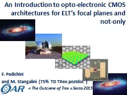
electronic CMOS architectures for ELTs focal planes and notonly F Pedichini and M Stangalini 75 TD TRex postdoc The ID: 708201

focal pixel pixels data pixel focal data pixels elt cmos amp limited spie detector time bit control transfer design

Share:

Link:

Embed:

Download Presentation from below link

Download Presentation The PPT/PDF document "An Introduction to opto-" is the property of its rightful owner. Permission is granted to download and print the materials on this web site for personal, non-commercial use only, and to display it on your personal computer provided you do not modify the materials and that you retain all copyright notices contained in the materials. By downloading content from our website, you accept the terms of this agreement.


Presentation Transcript

Slide1

An

Introduction

to opto-electronic CMOS architectures for ELT’s focal planes and not-only

F. Pedichiniand M. Stangalini (75% TD TRex postdoc ) « The Outcome of Trex » Sesto 2015Slide2

MOSAIC

consortium

for an E-ELT MOSMEMS deformable mirror (MOAO open loop)WF detectors technology

Direct vis. imagingSlide3

Trex

lab@Roma - (M.

Stangalini)Characterization of a 140 actuator MEMS-DM under open loop control for AO local correction in E-ELT MOS

Hardware delivered last week… results soon Slide4

Pixel_One

…a few years ago at San Diego SPIE 2010; Pedichini, Di Paola, Testa ...a possible technology to exploit

direct seeing limited imaging using the whole field of ELTs…Slide5

Overview of …

ELT@seeing.limited.it

Important numbers:Aperture ~ 40 mMirror surface > 1000m2F number 17.7 #Focal lenght > 700 mField of view ~ 5 x 5 arcmin2Scale 0.2 ÷ 0.3 arcsec/mm

Focal plane surface ~ 1m2 (@ 5 arcmin)Seeing FWHM 0.6-0.8 arcsecSlide6

Diffraction limited PSF vs.

seeing

The Airy disk diameter at λ=0.5µm is about 4 mas (18 µm) just two CCD pixels at ELT focal plane!

0.36 mm

100 masSlide7

…a different view….

at the

seeing scale

0.36 mm

100 mas

1.00 mm

300 mas

0.6 arcsec

seeing FWHM

5 arcmin

1000 mm

4k x 4k detector

with 15 µm pixels

At a

seeing limited

ELT

the use of standard detectors

gives

a factor thousand of oversampling

Instead

we would like a

Pixel_One

mm wide

ESO OmegacamSlide8

The Pixel_One

concept

TLR:1 pixel camera, ~1mm pitch, >1kHz, replicableSlide9

Optical and

S

ilicon pixels… matching

F# 17F# 1…One Big

focal reducer

&One standard detector

3x3 binned

very

expensive

glass

v

ery

demanding

optics

detector

cost

is

worth

F# 17

F#1

F#1

F#1

One

Million

of

tiny

focal

reducers

microlenses

&

One

Million

of

Pixel_One

cameras

a

replicable

CMOS

process

may be not

expensive Need

to develop it&

1m2 of silicon

(SPIE 2006 Gentile et al.) (SPIE 2010

Magrin et al.) (SPIE 2010 Ragazzoni et al.)

Building of a few 100 small

focal reducers to F#2÷4 with a binned

off the shelf sCMOS detector in a FlyEye

approachSlide10

µ-

lenses…!

Ø 40µmr 20µm

Ø 1mmSlide11

Bottom level:

the Pixel

A micro lens about 1 mm wide sample the focal plane.A “small” cmos-pixel converts photons to electrons and integrates the

charge.A local A/D digitizes at 8-12 bit and adds/stores the result.The ASIC manages the self-reset, the control signals, the data transfer on the local busses and the integration time.

A/D

register

State machine

I/O data bus

I/O data bus

Ø 30÷40 µm

1000 µmSlide12

Pixel features:

The local

A/D samples at kHz rates and digital integrates yelding an infinite dinamic

not limited by the pixel “fullwell” The state machine manages all the processes and transfer data to host.Current CMOS tecnology provides pixels with low RON. Less

than 1 e- expected

for Pixel_One

(Ybin

Bay et al. SPIE 2008, Downing et Al. SPIE 2012,

Fairchild

sCMOS

and

others

) Slide13

UMC CIS 180 IMAGE SENSOR ULTra

(4T) diode

Technology (D.I.Y.)NODE -> 180 nmInterconnect -> 2P4MVDD -> 1.8V core / 3.3V I/OMin Pixel Size

-> 2.6 umCapacitor -> Poly-Insulator-Poly, Metal-Insulator-Metal Digital design IP libraryCadence & Sysnopsys design flow

Analog design

Cadence FDK available

Pixel Design

Optical

simulation

support

Technology

evolution

-> 130 nm , 110 nm , 90 nm ready .. 65 nm

planned

(2011-12)

Exist

a MPW

path

at

Europractice

for a cheap

early

prototypingSlide14

Intermediate level: The Tile

We can mosaic an array of 32 x 32 Pixel_One on a single substrate and interconnect the data bus and control lines by means of an I/O digital circuit to PINS.

I/O logic

This is a very sparse CMOS on chip camera made of only 1024 pixel on a surface of about 32 x 32 mm

2

.

The I/O logic must allow the independent control of each single Pixel_One

(vital on an ELT’s imager)

…and

fill

ONE

squared

meter

of

(

curved

..?)

focal

plane

!Slide15

Backplane: Instructions for use

Pixel_One Backplane is a real parallel array of “smart” imagers and each “

pixel” of them can be programmed to accomplish different exposure times. This approach reduces the data rate and leave the fast sampling only where or when is really needed. (pre-imaging required)At an ELT a 32 bit equivalent photometric dynamic means to expose a 5 magV star for 500 ms with a gain of 1adu/e- without saturation of the full well.transfer data at

end of the exposuresaturation time 2E6 sec!Sky background21 magV/arcsec22000 e-/s90%fast variable Star22magV+sky

4000 e-/stransfer data at

each sample you need for science

10%

Bright field

Star

<15magV+sky

transfer data before

digital saturation of

32+ bit storage register

<1%Slide16

ADCs

IO LVDS

Pixel / die = 5x5 (

different)Total Pixels area 2500 µm2 Die area 5x5 mm2Sampling at 250 Kfps SAR ADC (12 bit)I/O (slave mode) -> about 10 Kbit/s

I/O (master mode) -> about

1 Mbit/s

32 bit

Adder

&

comp

Memory RF

Control

Logic

(D.I.Y.) a LABORATORY ON A die

MultiplexingSlide17

S/N optimization

Optical pixel size 1x1 mm, 4T pixel architecture, global Q.E. 50% (optics+silicon) RON 4e-.

No Cryo!Slide18

Conclusion

EUROPRACTICE

allows research institution to develop CMOS pixels at 30€ / mm2 (minimum

fee is 30k€)Mass production can be less 5€ / mm2 (to be investigated)400 well engineered cameras with focal reducers and lenses diameter of 70mm are

about 400 x 10K = 4 M€ !1

Million of Pixel_One may be

only 2 M€ ? (work in progress)

A LAST SLIDE >>>>Slide19

Not only

imaging… Pixel_One

for W.F.S. @ 1kHz WFS detector may saturate if magR < 7÷5Oversampling (> 1kHz) using

autoregressive prediction of turbulence on a few ms timescale may increase the Strehl by 50% factor (see: Stangalini, Arcidiacono AO4ELT 2013)

not

more

pixels

but

s

lopes

parallell

computedSlide20

A

B

D

C…not more pixels but Slopes or Centroids computed in parallell

i+1,j

i,j+1

i

,j-1

i,j

i-1,j

=


=


 Slide21

In X.A.O.

Shack Hartmann or

Pyramid uses several pixels (4x4+) to provide 2 slopes/ap…

Parallel acquisition and computing allow slow quiet and simpler architecture3kHzdetector 200 x 200

Preprocessor

Bias & Flat1 Gflops

1.5 Gb/s

Slope computing

2

0+

Gflops

6

M

float

/s

3kHz

Pixel_One

detector

200 x 200

6

M

float

/sSlide22

EUROPRACTICE

allows

research institution to develop CMOS

cameras using

180 micron-litography

at

low

cost

sharing

the

project

45

prototipes

with 5x5

pixel_one

= 30 k€ (VAT

inc

.)

UMC CIS180 Image

sensor

2P4M ULTRA

diode

Samples

> 45

Matrix

Chip

2x2

4x4

5x5

10x10

Area Chip (mm2)

4

16

25

100

APS x

batch

720

720

1125

4500

Chips x

batch

180

45

45

45

Blocks

x design

1

1

1

4

Cost

(die)

20400

20400

20400

81760

Packaging

3000

30003000

3000

2012 costs estimate by courtesy

of A. Bartoloni

(INFN, CERN)

If a new Trex

funding or something else….Slide23

No

evident showstopper in

PixelOneThank you for your attention…any question?Slide24

PixelOne*@ E.ELT

Photometric S/N

vs integration time in seconds for Pixel-One used as a fast photometer and for Pixel-One used as a faint sources imager at the Nasmith focus of the future E-ELT in V band with 0.8” seeing, sky mag. = V 21.

*In the “Italian slang” PixelOne sounds like “a big pixel”.Slide25

Science cases for Pixel_One… (finally)

High-frequency time sampling of compact objects

: like pulsars, magnetars, etc, can be observed with a time sampling of the order of 10-3-10-2 , Vmag~20 (10σ), while in 1s the 10σ limiting magnitude is V~24.3Faint galactic halo objects: e.g. brown dwarfs. Faint objects around brighter sources: imaging big galaxies concentrating on spiral arms avoiding the bright bulges saturation

Rapidly variable phenomena: it is possible to follow rapidly variable phenomena with high efficiency. Typical targets are contact binaries and short period variables.Other targets: in general any program that requires seeing-limited conditions can be carried out with Pixel_One. Even moderately crowded fields can be observed with a special attention to faint objects without “bleeding and saturation”“It is worth stressing that the relatively large field-of-view makes it possible to execute surveys, thus conjugating speed of acquisition with sky coverage.”