/
Int. J. Mech. Eng. & Rob. Res. 2012 Int. J. Mech. Eng. & Rob. Res. 2012

Int. J. Mech. Eng. & Rob. Res. 2012 - PDF document

sherrill-nordquist
sherrill-nordquist . @sherrill-nordquist
Follow
426 views
Uploaded On 2016-08-27

Int. J. Mech. Eng. & Rob. Res. 2012 - PPT Presentation

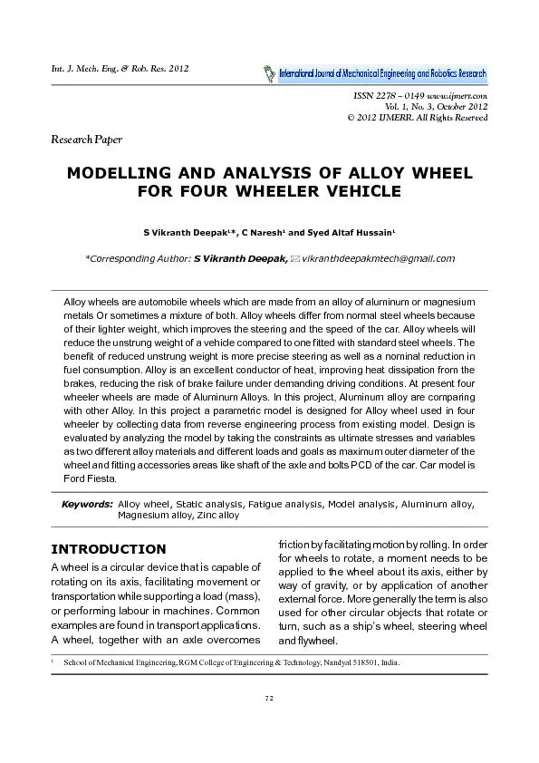
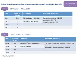
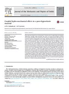
72 S Vikranth Deepak et al 2012MODELLING AND ANALYSIS OF ALLOY WHEELFOR FOUR WHEELER VEHICLES Vikranth Deepak1 C Naresh1 and Syed Altaf Hussain1Corresponding Author S Vikranth Deepakrvikranth ID: 457838

72 S Vikranth Deepak al.

Share:

Link:

Embed:

Download Presentation from below link

Download Pdf The PPT/PDF document "Int. J. Mech. Eng. & Rob. Res. 2012" is the property of its rightful owner. Permission is granted to download and print the materials on this web site for personal, non-commercial use only, and to display it on your personal computer provided you do not modify the materials and that you retain all copyright notices contained in the materials. By downloading content from our website, you accept the terms of this agreement.


Presentation Transcript

72 Int. J. Mech. Eng. & Rob. Res. 2012 S Vikranth Deepak et al., 2012MODELLING AND ANALYSIS OF ALLOY WHEELFOR FOUR WHEELER VEHICLES Vikranth Deepak1*, C Naresh1 and Syed Altaf Hussain1*Corresponding Author: S Vikranth Deepak,\rvikranthdeepakmtech@gmail.com Alloy wheels are automobile wheels which are made from an alloy of aluminum or magnesiummetals Or sometimes a mixture of both. Alloy wheels differ from normal steel wheels becauseof their lighter weight, which improves the steering and the speed of the car. Alloy wheels willreduce the unstrung weight of a vehicle compared to one fitted with standard steel wheels. Thebenefit of reduced unstrung weight is more precise steering as well as a nominal reduction infuel consumption. Alloy is an excellent conductor of heat, improving heat dissipation from thebrakes, reducing the risk of brake failure under demanding driving conditions. At present fourwheeler wheels are made of Aluminum Alloys. In this project, Aluminum alloy are comparingwith other Alloy. In this project a parametric model is designed for Alloy wheel used in fourwheeler by collecting data from reverse engineering process from existing model. Design isevaluated by analyzing the model by taking the constraints as ultimate stresses and variablesas two different alloy materials and different loads and goals as maximum outer diameter of thewheel and fitting accessories areas like shaft of the axle and bolts PCD of the car. Car model is Ford Fiesta.Keywords:Alloy wheel, Static analysis, Fatigue analysis, Model analysis, Aluminum alloy, Magnesium alloy, Zinc alloy INTRODUCTIONA wheel is a circular device that is capable ofrotating on its axis, facilitating movement ortransportation while supporting a load (mass),or performing labour in machines. Commonexamples are found in transport applications.A wheel, together with an axle overcomes ISSN 2278 – 0149 www.ijmerr.comVol. 1, No. 3, October 2012© 2012 IJMERR. All Rights ReservedInt. J. Mech. Eng. & Rob. Res. 2012 1School of Mechanical Engineering, RGM College of Engineering & Technology, Nandyal 518501, India.friction by facilitating motion by rolling. In orderfor wheels to rotate, a moment needs to beapplied to the wheel about its axis, either byway of gravity, or by application of anotherexternal force. More generally the term is alsoused for other circular objects that rotate orturn, such as a ship’s wheel, steering wheeland flywheel.Research Paper 73 Int. J. Mech. Eng. & Rob. Res. 2012 S Vikranth Deepak et al., 2012TYPES OF WHEELSThere are only a few types of wheels still inuse in the automotive industry today. They varysignificantly in size, shape, and materials used,but all follow the same basic principles.The first type of wheel worth mentioning, andby far the most-used wheel, is the steel wheel.This kind of wheel consists of several sheetsof steel, stamped into shape and typicallywelded together. This type of wheel is strong,but heavy. They are found on every kind ofvehicle from sports cars to the larger pickuptrucks; the wheels look different but areessentially the same device.The second type of wheel to be mentionedis the rally wheel. These are essentially steelwheels but they are made somewhat differently,and tend to consist of a heavier gauge of steel.While the inner portion of a steel wheel isgenerally welded to the rim along its entirecircumference, a steel wheel’s inner portion iscut to resemble the spokes of a mag wheel,and is welded accordingly.Mag wheels are cast and/or milled wheelstypically made from aluminum or an alloythereof. They used to be made of magnesiumfor their light weight and strength, butmagnesium catches fire somewhat easilyand is very difficult to put out. This isunfortunate, because it is superior toaluminum in every other way. This tendencyalso makes it a dangerous metal to work with,because piles of shavings tend to burst intoflame and burn through concrete surfaceswhen they get too hot.As previously mentioned, spoke wheels(sometimes with more than 100 spokes) arestill in use today and are popular on roadstersand low-riders. They tend to be fairly low inweight, and are reasonably strong. They havean “old school” appearance and style which isoften highly sought after.Various combinations of these technologiescan be used to produce other, more unusualwheels. Large earth-moving vehicles such asthe more gargantuan dump trucks often havesome degree of the vehicle’s suspensionactually built into the wheel itself, lying betweenthe hub and rim in place of spokes. Also,various companies make wheels which aredesigned like steel wheels but are made ofaluminum. The most famous of these are madeby centerline, and the style is actually calledthe centerline wheel.SPECIFICATION OF THEPROBLEMAluminum alloy are comparing with other Alloy.In this project a parametric model is designedfor Alloy wheel used in four wheeler by collectingdata from reverse engineering process fromexisting model. Design is evaluated byanalyzing the model by taking the constraintsas ultimate stresses and variables as twodifferent alloy materials and different loads andgoals as maximum outer diameter of the wheeland fitting accessories areas like shaft of theaxle and bolts PCD of the car. Car model isFord Fiesta.COMPOSITE MATERIALSA composite material is defined as a materialcomposed of two or more constituentscombined on a macroscopic scale bymechanical and chemical bonds.Composites are combinations of twomaterials in which one of the material is called 74 Int. J. Mech. Eng. & Rob. Res. 2012 S Vikranth Deepak et al., 2012the “matrix phase” is in the form of fibers,sheets, or particles and is embedded in theother material called the “reinforcing phase”.Another unique characteristic of many fiberreinforced composites is their high interaldamping capacity. This leads to bettervibration energy absorption within the materialand results in reduced transmission of noiseto neighboring structures. Many compositematerials offer a combination of strength andmodulus that are either comparable to orbetter than any tradional metalic metals.Because of their low specific gravities, thestrength to weight-ratio and modulus to weight-ratios of these composite materials aremarkedly superior to those of mettalicmaterials.The fatigue strength weight ratios as wellas fatigue damage tolerances of manycomposite laminates are excellent. For thesereasons, fiber composite have emerged asa major class of structural material and areeither used or being considered assubstitutions for metal in many weight-criticalcomponents in aerospace, automotive andother industries.SPECIFICATION OFEXISTING ALLOY WHEELTable 1 shows the specifications of a FordFiesta car. The typical chemical compositionof the material for Alluminium alloy(%) iscopper-0.25,maganese-0.35,silicon-6.5 to7.5, iron-0.6%, zinc-0.35, others-0.05,alluminum-87 to 100.Magnisium alloy (%) is maganese-0.6 to1.4, calcium-0.04, silicon-0.1, copper-0.05,nickel-0.005, iron-0.005, magnisium-85 to100. S. No.ParametersValue1.Area196761.05 mm22.Diameter280 mm3.Perimeter1759.29 mm4.Weight of the Car1.5 Tonnes5.Passenger 5 People400 KG6.Extra Load500 KG7.Total23520 N8.Tyres and SuspensionReduced by 30%16464 N9.Weight on Individual Wheel4116 N10.Pressure0.08 N/mm2Table 1: Specifications of Alloy Wheel Zincalloy (%) isalluminum-3.7 to 4.3,copper-0.1, iron-0.05, lead-0.003, cadmium-0.002, tin-0.001, nickel-0.005 to 0.020, zinc-70 to 100.STRUCTURAL ANALYSIS OFALLOY WHEELStatic analysis calculates the effects of steadyloading conditions on a structure, whileignoring inertia and damping effects, such asthose caused by time-varying loads. A staticanalysis, however, includes steady inertialoads (such as gravity and rotational velocity),and time-varying loads that can beapproximated as static equivalent loads (suchas the static equivalent wind and seismic loadscommonly defined in many building codes).Loads in a Structural AnalysisStatic analysis is used to determine thedisplacements, stresses, strains, and forcesin structures or components caused by loadsthat do not induce significant inertia anddamping effects. Steady loading and responseconditions are assumed; that is, the loads andthe structure’s response are assumed to vary 75 Int. J. Mech. Eng. & Rob. Res. 2012 S Vikranth Deepak et al., 2012slowly with respect to time. The kinds of loadingthat can be applied in a static analysis include(Table 2): •Externally applied forces and pressures.•Steady-state inertial forces (such as gravityor rotational velocity).•Imposed (non-zero) displacements.•Temperatures (for thermal strain). Table 2: Comparative Static Analysis of Alloy Wheels for Different Materials Alluminuim0.001651502.1142800.003825731.61658e-0082.53612e-005Zinc0.001672292.1160200.003254931.29709e-0082.11336e-005Magnesium0.001393682.1033000.006170552.96084e-0084.26829e-005 Static Analysis Stress (N/mm2)Displacement (mm)StrainMinMaxMinMaxMinMax CONCLUSIONA fatigue lifetime prediction method of alloywheels was proposed to ensure their durabilityat the initial design stage. To simulate the rotaryfatigue test, static load FEM model was builtusing COSMOS. The analysis results showedthat the maximum stress area was located inthe hub bolt whole area agreed with the fact.Therefore, the finite element model canachieve results consistent with that obtainedfrom the actual static load test. The nominalstress method was used to predict the fatiguelife of alloy wheels. In the nominal stressmethod, the fatigue life of alloy wheels waspredicted by using alloy wheel S-N curve andequivalent stress amplitude. The simulationresult showed that baseline design fatigue lifewas lower than 1 u 105. After improving theweakness area of alloy wheels, the improvedwheel life cycle exceeded 1 u 105 and satisfiedthe design requirement.Alloy wheel rotary fatigue bench test wasconducted. The test result showed that theprediction of fatigue life was consistent withthe physical test result. These results indicatethat the fatigue life simulation can predictweakness area and is useful for improvingalloy wheel. These results also indicate thatintegrating FEA and nominal stress method isa good and efficient method to predict alloywheels fatigue life. For all comparing the threematerials of stress, strain, displacement, total Table 3: Comparative Fatigue Analysis of Alloy Wheels for Different Materials Alluminuim1e + 0061e + 006101092.7230115533Zinc1e + 0061e + 0061010108.7550130539Magnesium1e + 0061e + 006101057.846580884.7 Fatigue Analysis Total Life (Cycles)Damage FactorLoad FactorMinMaxMinMaxMinMax 76 Int. J. Mech. Eng. & Rob. Res. 2012 S Vikranth Deepak et al., 2012life, load factor and damage factor we suggestthat aluminum alloy is the best material for thealloy wheel (Table 3).Alluminuim0962.280Zinc0612.849Magnesium01208.220Table 4: Comparative Frequency Analysisof Alloy Wheels for Different Materials Frequency Analysis Displacement (mm)MinMax REFERENCES1.Liangmo Wang, Yufa Chen, ChenzhiWang and Qingzheng Wang (2011),“Fatigue Life Analysis of AluminumWheels by Simulation of Rotary FatigueTest”, Strojniski Vestnik-Journal ofMechanical Engineering, Vol. 57, No. 1,pp. 31-39.2.Mohd Izzat Faliqfarhan Bin Baharom(2008), “Simulation Test of AutomotiveAlloy Wheel Using Computer AidedEngineering Software”, Eng.D. Thesis,University Malaysia Pahang.3.Nitin S Gokhale (1999), Practical FiniteElement Analysis.4.Si-Young Kwak, Jie Cheng and Jeong-KilChoi (2011), “Impact Analysis of CastingParts Considering Shrinkage CavityDefect”, China Foundry, Vol. 8, No. 1,pp. 112-116.5.WenRu Wei, Liang Yu, Yanli Jiang,JunChuan Tan and Ru HongQiang(2011), “Fatigue Life Analysis ofAluminum HS6061-T6 Rims Using FiniteElement Method”, InternationalConference on Remote Sensing,Environment and TransportationEngineering, pp. 5970-5973. APPENDIX Figure 1: Stress on Alluminium Alloy Figure 2: Strain on Alluminium Alloy 77 Int. J. Mech. Eng. & Rob. Res. 2012 S Vikranth Deepak et al., 2012APPENDIX Figure 3: Displacement on Alluminium Alloy Figure 4: Stress on Magnesium Alloy Figure 5: Displacement on Magnesium Alloy Figure 6: Strain on Magnesium Alloy Figure 7: Stress on Magnesium Alloy Figure 8: Displacement on Magnesium Alloy 78 Int. J. Mech. Eng. & Rob. Res. 2012 S Vikranth Deepak et al., 2012APPENDIX (CONT.) Figure 9: Strain on Magnesium Alloy Figure 10: Total Life on Alluminium Alloy Figure 11: Damage Percentage onAlluminium Alloy Figure 12: Load Factor on Alluminium Alloy Figure 13: Total Life on Magnesium Alloy Figure 14: Damage Percentage onMagnesium Alloy 79 Int. J. Mech. Eng. & Rob. Res. 2012 S Vikranth Deepak et al., 2012APPENDIX (CONT.) Figure 15: Load Factor on Magnesium Alloy Figure 16: Total Life on Zinc Alloy Figure 17: Damagage Percentagon Zinc Alloy Figure 18: Frequency of Alluminium Alloy Figure 19: Frequency of Magnesium Alloy Figure 20: Frequency of Zinc Alloy 80 Int. J. Mech. Eng. & Rob. Res. 2012 S Vikranth Deepak et al., 2012APPENDIX (CONT.) Figure 21: SN Curves for Alternating Atress and Cycles of a Aluminum Alloy Figure 22: SN Curves for Alternating Stress and Cycles of a Magnesium Alloy Figure 23: SN Curves for Alternating Stress and Cycles of a Zinc Alloy