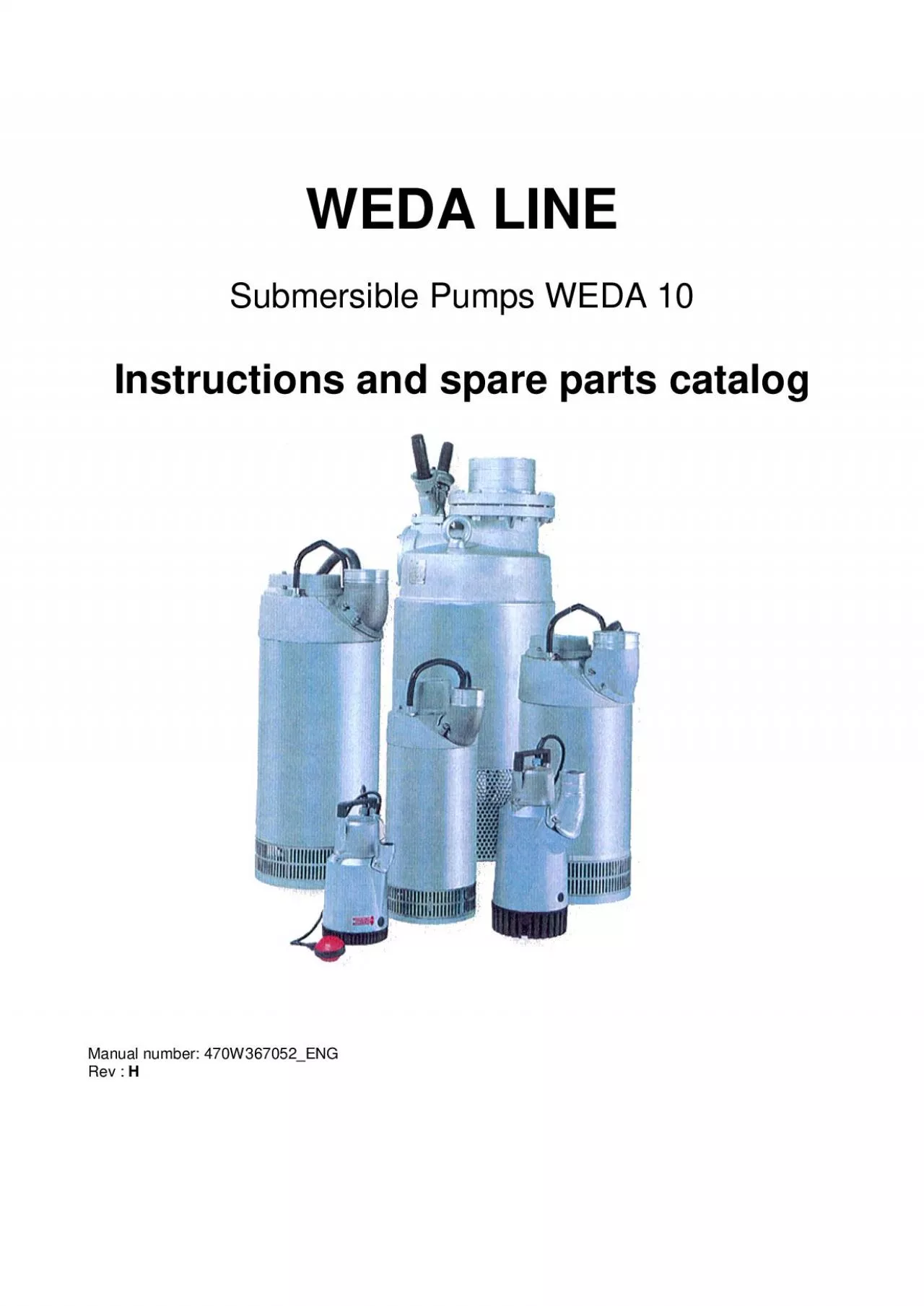
/
WEDA LINE Submersible Pumps WEDA 10 Instructions and spare parts catal WEDA LINE Submersible Pumps WEDA 10 Instructions and spare parts catal

WEDA LINE Submersible Pumps WEDA 10 Instructions and spare parts catal - PDF document

singh
singh . @singh
Follow
344 views
Uploaded On 2021-06-20

WEDA LINE Submersible Pumps WEDA 10 Instructions and spare parts catal - PPT Presentation

Manual number 470W367052ENG Rev INSTRUCTIONS MANUAL ID: 845912

cable pump weda instructions pump cable instructions weda parts manual pumps phases part safety pos switch voltage phase impeller

Share:

Link:

Embed:

Download Presentation from below link

Download Pdf The PPT/PDF document "WEDA LINE Submersible Pumps WEDA 10 Inst..." is the property of its rightful owner. Permission is granted to download and print the materials on this web site for personal, non-commercial use only, and to display it on your personal computer provided you do not modify the materials and that you retain all copyright notices contained in the materials. By downloading content from our website, you accept the terms of this agreement.


Presentation Transcript

1 WEDA LINE Submersible Pumps WEDA 10 Inst
WEDA LINE Submersible Pumps WEDA 10 Instructions and spare parts catalog Manual number: 470W367052_ENG Rev : INSTRUCTIONS MANUAL – WEDA 102/19 GENERAL SAFETY RULES WARNINGRead and understand all instructions Failure to follow all instructions listed below, may result in electric shock, fire and/or serious injury. Before using the machine, read carefully these instructions and keep them in a safe place. These safety recommendations have been compiled from international safety standards. Local regulations must also be checked and observed. SAVE THESE INSTRUCTIONS WORK AREA Keep your work area clean and well lit. Cluttered benches and dark areas invite accidents. Do not operate pumps in explosive atmospheres, such as presence of flammable liquids, gases or dust. Pumps creates sparks which may ignite the dust or fumes. Keep bystanders, children, and visitors away while operating a pump. Distraction can cause you to loose control. ELECTRICAL SAFETY Pumps must be plugged into an outlet properly installed and grounded in accordance with all co

2 des and ordinances. Never remove the gro
des and ordinances. Never remove the grounding prong or modify the plug in any way. Do not use any adaptor plugs. Check with a qualified electrician if you are in doubt as to whether the outlet in properly grounded. If the pumps should electrically malfunction or break down, grounding provides a low resistance path to carry electricity away from the user. Avoid body contact with grounded surfaces such as pipes, radiators, ranges and refrigerators. There is an increase risk of electric shock if your body is grounded. Do not abuse the cord. Never use the cord to carry the pumps or pull the plug from an outlet. Keep cord away from heat, oil, sharp edges or moving parts. Damaged cords increase the risk of electric shock. Use a network protected by a ground fault circuit interrupter. PERSONAL SAFETY Stay alert, watch what you are doing and use common sense when operating a pump. Do not use pump while tired or under influence of drugs, alcohol or medication. A moment of inattention while operating pumps result in serious personal injury. Dress properly.

3 Do not wear loose closing or jewellery.
Do not wear loose closing or jewellery. Contain long hair. Keep your hair, clothing, and gloves away from moving parts. Loose clothes, jewellery, or long hair can be caught in moving parts. Always use approved safety equipment. Always wear eye protection. The following safety equipment applies to operators and other personnel in the immediate vicinity of the working zone. Safety helmet. Ear protectors. Dust mask in dusty environments. Protective gloves. Protective shoes. Goggles. INSTRUCTIONS MANUAL – WEDA 103/19 Remove adjusting keys or switches before turning the pump on. A wrench or a key that is left attached to a rotating part of the pump may result in personal injury. The admissible sound level of 85 dB (A), can be exceeded because of the machine and/or the application. Long time exposure to loud noise without ear protectors can cause permanent damage to hearing. PUMP USE AND CARE Never operate the pump without the strainer. It both protects the pumps and the pipes.Do not force pump. Use the correct pump for your application. The corre

4 ct pump will do the job better and safer
ct pump will do the job better and safer at the rate for which it is designed. The use of the machine is restricted to the applications specified in the product literature. Disconnect the plug from the power source before making any adjustments, changing accessories, or storing the pump. Such preventive safety measures reduce the risk of starting the pump accidentally. Store idle pumps out of reach of children and other untrained persons. Pumps are dangerous in the hand of untrained users. Maintain pumps with care. Properly maintained pumps are less likely to bind and are easier to control. Check for misalignment or binding of moving parts, breakage of parts, and any other condition that may affect the pumps operation. If damaged, have the pump serviced before using. Many accidents are caused by poorly maintained pumps. The machine must not be modified without prior consent of the manufacturer. Use only original parts. If modifications are made without prior consent of the manufacturer there is a risk of serious injury to the personal. SERVICE

5 Pump service must be performed only by
Pump service must be performed only by qualified repair personnel. Service or maintenance performed by unqualified personnel could result in a risk of injury. When servicing a pump, use only identical replacement parts. Follow instructions in the Maintenance section of this manual. Use of unauthorized parts or failure to follow Maintenance Instructions may create a risk of electric shock or injury. Make sure that the signs about using, safety, and maintenance are always legible. Always change damaged parts immediately. Change wear parts in due time. INSTRUCTIONS MANUAL – WEDA 104/19 GENERAL The WEDA submersible drainage pumps are designed for pumping lightly contaminated water. DESIGN The heavy duty light weightaluminium construction includes a cooling jacket ensuring adequate motor cooling at all times. The WEDA LINE pumps are in 'plug and pumping design’, with built-in full overheat motor protection. The versions with level float switch allow automatic operation.The unique cartridge type seal package can be easily replaced on site with only

6 minimum downtime. For demanding applica
minimum downtime. For demanding applications as in construction works and mining, the impellers are made for wear resistant Hi-Chrome iron and all other components are rubber lined. The impeller clearance is easily adjustable to compensate for wear. TECHNICAL DATA Pump : WEDA10N Discharge mm - (in) 50 - (2") Suitable for media with pH 5 - 8 Maximum water temperature 40°C Maximum submersible depth m - (ft) 20 - (67) Maximum solids size mm - (in) Ø4 - (0.16) Weight (excluding cable ) kg - (lb) 12.50 - (27.50) Strainer Rectangular holes 4 x 27 mm Speed rpm 50Hz (60Hz) 2980 - (3550) Stator insulation class F (155°C) Voltages V Phases Frequency Hz Rated current A Rated electrical power (kW) 110 1 50 12.8 1.4 220-240 1 50 6.1 1.4 380-415 3 50 2.3 1.4 115 1 60 13 1.4 220 1 60 6.2 1.4 440 3 60 2.2 1.4 Other voltages upon request IMPORTANT The above information is a general description only, is not guaranteed and contains no warranties of any kindPower cables (50Hz) Power cables (60Hz) only for CSA approved types 15 met

7 ers 3x2.5 mm2 for 110 V ' 1 phase . 15 m
ers 3x2.5 mm2 for 110 V ' 1 phase . 15 meters SOW 3xAWG14 for 110V - 1 phase 20 meters 3x1.5 mm2 for 220-240 V ' 1 phase . 20 meters SOW 3xAWG16 for 220V-240V - 1 phase 20 meters 4x1.5 mm2 for other voltages. 20 meters SOW 4xAWG16 for 440V-460V - 3 phases All cables polychloroprene type HO7RN-F . INSTRUCTIONS MANUAL – WEDA 105/19 100 200 300 400 500 600 700 800 1,5 2,5 4 6 10       cable section (mm2) cable length authorized (m) HYDRAULIC CHARACTERISTICS 50Hz 60Hz 120 240 360 480 600 720 840 L/ mn INSTRUCTIONS MANUAL – WEDA 106/19 DIMENSIONS DISCHARGES AVAILABLE PART NUMBER 2" Hose standard with 1 clamp 470W214251 2" BSP - thread 470W214280 2" NPT - thread 470W214489 The discharges have to be ordered separately . dimensions in mm/inch INSTRUCTIONS MANUAL – WEDA 107/19 INSTALLATION The pump must not be used in an explosive / inflammable environment or used to pump inflammable liquids ! Route the cables so that connectors do not lie in the water. Consider the risk of

8 electrical accident. Never lift the pum
electrical accident. Never lift the pump by its power cable ! Connect a discharge hose of approved pressure class. The discharge hose may be thrown off when the pump starts. No one must be allowed in the water, e.g. swimming pools, when the pump is running. Check that the pump is standing steady, or suspend it from its lifting ring. Check the direction of rotation, pointed by the starting kick arrow printed in the outer casing (anticlockwise) The pump will start instantaneously when it is connected to the power supply. The pump may kick violently when it starts. In case of wrong direction of rotation two phases should be inverted from the supply (three phases voltage only). Direction of rotation ELECTRICAL CONNECTION Check that the details on the pump data plate match with the mains voltage and frequency. The electrical installation must be carried out by a qualified electrician ! Local installation regulations must be followed ! Make sure that the pump is properly earthed. The earth conductor must be slightly longer than the pha

9 se conductors. If the motor power cable
se conductors. If the motor power cable is accidentally pulled off, the earth conductor must be the last conductor to be removed from the terminals. USE WITH APPROVED MOTOR CONTROL THAT MATCHES MOTOR INPUT IN FULL LOAD AMPERES WITH OVERLOAD ELEMENTS SELECTED OR ADJUSTED IN ACCORDANCE WITH THE CONTROL INSTRUCTIONS" BUILT-IN MOTOR PROTECTION Check that the pump is disconnected from the power supply before starting any work ! The pump's built-in motor protection switches off the contactor automatically if the motor overheats. Then, the fault must be identified and corrected. After cooling to normal working temperature, the motor protection switches on the contactor and the pump starts again. Neutral INSTRUCTIONS MANUAL – WEDA 108/19 TROUBLE SHOOTING Fault location Cause Action Pump will not start. 1. Fuses blown 2. Broken cable 3. Power failure 4. Jammed impeller 5. Faulty contactor 6. Stator winding burnt-out 7. Incorrect phase sequence (3 phases) 1. Replace fuses 2. Service 3. – 4. Clean bottom of pump 5. Service 6. Service 7. Change 2 p

10 hases in plug Pump starts, but stops ag
hases in plug Pump starts, but stops again. 1. Pump runs backwards (3 phases) 2. Pump connected to wrong voltage 3. Phase interruption 4. Strainer blocked 5. Insufficient water level 6. Voltage too low when using an extra cable 7. Water too hot 1. Change 2 phases in plug 2. Select the right voltage 3. Check fuses 4. Clean strainer 5. Stop the pump 6. Increase the extra cable section 7. Switch off power Pump works, but delivers too small water volume . 1. Impeller worn 2. Pump runs backwards (3 phases) 3. Hose dimensions unsuitable 4. Insufficient discharge head 1. Adjust pump/replace impeller 2. Change 2 phases in plug 3. Change to suitable hose 4. Select a bigger pump MAINTENANCE PUMP PERFORMANCE To keep the pump performance, the gaps must be as small as possible. The gap between the impeller and the wear plate is adjustable with trim washers. The gap between the impeller and the diffusor is adjusted by alternatively tightening the nuts fixing the diffusor. After adjustment the impeller must be capable of rotation by hand. Worn impell

11 er can have very sharp edges . Wear safe
er can have very sharp edges . Wear safety gloves ! SHAFT SEAL UNIT The WEDA10 bearings are greased for life with high temperature grease and anti-corrosion additive. No inspection required between service intervals. Recommended lubricant: TRIBOTEC OKS400/00: Universal Heavy Duty grease. Grease each 4-6 months the shaft seal through the grease nipple situated on the pump body (Fig 1) . When servicing replace systematically following parts: Items: 61 and 63. See spare part pages.Fig 1 MAINTENANCE KITS Part numberDescriptionParts included 470W214879 Gasket set Parts 19 , 24 , 30 , 48 , 49 , 55 , 62 , 64. 470W214880 Wear part set RL2014 - 50Hz Parts 65 , 67 , 68 , 70 . 470W214881 Wear part set RL2015 - 60Hz Parts 65 , 67 , 68 , 70 . 470W368043 Grease amount 0,5 L - 470W368009 Grease gun - Note: Refer to spare part pages . INSTRUCTIONS MANUAL – WEDA 109/19 ACCESSORIES FIRE BRIGADE COUPLING DN40 : 470W36801 DN65 : 470W367891 (threaded on discharge 2" BSP : 470W214280) FLOOR LEVEL BAND P/N 470W214800 (POS 74) FLOAT SWITCH P/N 470W214842 W

12 EDA10 series pump can be equipped with a
EDA10 series pump can be equipped with a float switch. Switching on an off is regulated by the length of the float switch cable. See fig. 5, 6. Fig. 5 Fig. 6 ASSEMBLING OF FLOAT-SWITCH 1. Dismantle pos. 7, 8, 9 and 10, use a hexagon key size 8. 2. Put pos. 36 and 8 on the cable. 3. Place pos. 40 approx. 300 mm on the cable, use soap water. 4. Assemble float-switch on the cover, use spanner size 19. 5. Assemble pos. 38 and 39, use screw driver. 6. Place pos. 41 on the cable .With this clamp (pos. 41) the cable can be shorten. 7. Dismantle M6 nut at A, place pos. 42 and put the nut back, use spanner size 10.Pos. 42 is a holder for the float at transport. ZINC ANODES P/N 470W209289 When pumping salt water (which is highly aggressive towards aluminium), the pump should be protected with zinc anodes. INSTRUCTIONS MANUAL – WEDA 1010/19 INSTALLATION WIRING DIAGRAMS WIRING DIAGRAM 1 PHASE WIRING DIAGRAM Y CONNECTION 3 PHASES INSTRUCTIONS MANUAL – WEDA 1011/19 WIRING DIAGRAM CONNECTION 3 PHASES FLOAT SWITCH CONNECTIONS PUMPS

13 WITH CONTROL RELAY. The relay aims to c
WITH CONTROL RELAY. The relay aims to control the direction of the rotation as well as the voltage supply. The pump will not start either if the phases sequence is not suitable or if one phase is missing. Therefore if the pump does not start: 1. Check the voltage supply: if wrong, correct the situation. 2. If the voltage supply is right , switch off the pump , then move the black wire of the cable from the cable terminal 2 to the terminal 4 and proceed in reverse order for the blue wire : from 4 to 2 . 3. Switch on the pump, it has to rotate in the right direction and the relay led is lighted. WIRING DIAGRAM Y CONNECTION 3 PHASES WITH CONTROL RELAY INSTRUCTIONS MANUAL – WEDA 1012/19 WIRING DIAGRAM CONNECTION 3 PHASES WITH CONTROL RELAY INSTRUCTIONS MANUAL – WEDA 1013/19 SPARE PARTS CATALOGUE RESERVDELSTÄLLNING Följande uppgifter ska lämmas vid beställning av reservdelar för att undvika leveransfel : 1. Maskintyp. 2. Maskinens seriunmmer. 3. Antal av önskad reservdel. 4. Reserdelens artikelnummer. 5. Reservedelens benämning. 6. Måttupgif

14 ter vid beställning av metervara.ORDERIN
ter vid beställning av metervara.ORDERING SPARE PARTS To avoid errors in delivery, please give the following information when ordering spare parts : 1. Type of machine. 2. Machine serial number. 3. Quantity required. 4. Part number. 5. Parts description. 6. Dimensions when ordering per length.ERSATZTEILBESTELLUNG Zur Vermeidung von Fehllieferungen sind bei der Bestellung von Ersatzteilen folgende Angaben zu machen : 1. Mashinentyp. 2. Herstellungsnummer. 3. Bestellmenge. (Quantity) 4. Ersatzteilbenennung. (Part N°) 5. Ersatzteilbenennung. (Description) 6. Massangaben bei Bestellung von Meterware.ORDINI DI RICAMBI Per evitare errori nelle consegne di ricambi, Vi preghiamo di comunicarci le seguenti informazioni al momento dell ‘ordinazione : 1. Tipo di macchina. 2. Numero di serie della macchina. 3. Quantitá dei pezzi desiderati. (Quantity) 4. Numero di codice del pezzo. (Part N°) 5. Descrizione del pezzo di ricambio. (Description)6. Misura, in caso di ordine per metro.PEDIDO DE RECAMBIOS Para evitar errores en las entregas, deberá indicarse los sigu

15 ientes datos al hacer un pedido de recam
ientes datos al hacer un pedido de recambios : 1. Tipo de máquina. 2. Número de serie. 3. Cantidad de piezas deseadas. (Quantity) 4. Número de artículo de la pieza de recambio. (Part N°) 5. Denominación de la pieza. (Description) 6. Indíquese la medida al solicitar un artículo que se expide por metros.COMMANDE DE PIECES DE RECHANGE Les indications suivantes doivent être fournies lors de la commande de pièces de rechange, afin d’éviter toute erreur de livraison : 1. Type de machine. 2. Numéro de série. 3. Quantité désirée de pièce de rechange. (Quantity) 4. Numéro de la pièce de rechange. (Part N°) 5. Description de la pièce de rechange. (Description) 6. Longueur en cas de commande par mètre. INSTRUCTIONS MANUAL – WEDA 1014/19 SPARE PARTS Note : To place spare parts order, use : - The serial number of the machine - The description and part number.Qty Ref Designation P/N 110V -1~ 230V -1~ -3~- Cable 3x2.5 mm, 15m 470W214845 1 - - Cable 3x1.5 mm, 20m 470W214846 - 1 - Cable 4x1.5 mm, 20m 470W214847 - - 1 Cable CSA SOW 3xAWG14, 15

16 m 470W367173 1 - - Cable CSA SOW 3xAW
m 470W367173 1 - - Cable CSA SOW 3xAWG16, 20m 470W367174 - 1 - 1 Cable CSA SOW 4xAWG16, 20m 470W367175 - - 1 3 Cable inlet cpl. Incl.2,4,5 470W214639 1 1 1 Cable sleeve 470W214394 1 - - Cable sleeve 470W214839 - 1 - 6 Cable sleeve 470W214838 - - 1 7 Blind plug 470W214828 1 1 1 8 Washer 470W214825 1 1 1 9 Rubber gasket 470W214829 1 1 1 10 Washer 470W214833 1 1 1 11 Contactor cover 470W212849 1 1 1 12 Nut 4700W84207 15 15 15 Wiring diagram 1 phase 470W214834 1 1 - Wiring diagram 470W214836 - - 1 13 Wiring diagram Y 470W214835 - - 1 16 Screw 470W209902 5 5 4 17 Capacitor holder 470W214821 1 - - 18 Capacitor compl. 470W214830 1 - - 19 O-ring 4700W65112 2 2 2 21 Stud bolt 470W214111 3 3 3 23 Washer 4700W51163 2 2 2 24 Teflon washer 470W214622 2 2 2 25 Contactor (see below) 26 Contactor holder 470W214871 1 1 1 Data plate (CE) 470W743583 1 1 1 27 Data plate (CSA) 470W743612 1 1 1 28 Rivet 4700W65431 4 4 4 Discharge 2” for hose 470W214

17 251 1 1 1 Discharge 2" BSP-thread 47
251 1 1 1 Discharge 2" BSP-thread 470W214280 1 1 1 29 Discharge 2" NPT thread 470W214489 1 1 1 30 Discharge gasket 470W214186 1 1 1 31 Stud bolt 4700W69609 2 2 2 32 Outer casing 470W211102 1 1 1 33 Lubrication plate 470W209203 1 1 1 34 Rivet 4700W65431 2 2 2 35 Rubber plug 470W214187 1 1 1 36 Cable inlet cpl. (8,38,39) 470W743411 1 1 1 37 Float switch 470W214842 1 1 1 40 Cable sleeve 470W214826 1 1 1 41 Clamp 470W209900 1 1 1 42 Float holder clamp 470W213843 1 1 1 INSTRUCTIONS MANUAL – WEDA 1015/19 43 Capacitor 470W740194 - 1 - 44 Capacitor holder 470W214841 - 1 - 45 Spring washer 4700W58956 1 1 1 46 Washer 470W45883 1 1 1 47 Bearing bracket upper 470W208138 1 1 1 48 O ring 470W65021 1 1 1 49 O ring 470W65115 2 2 2 50 Stator (see below) 51 Stud bolt 470W69617 2 2 2 52 Inner casing 470W212831 1 1 1 53 Ball bearing upper 4700W61007 1 1 1 470W730077 1 1 1 54 Rotor with shaft From S/N : 1011027 4812050502 1 1 1 470W65081 1 1 1 55 O ring From

18 S/N : 1011027 4700891373 1 1 1 56 Bea
S/N : 1011027 4700891373 1 1 1 56 Bearing bracket lower 470W212782 1 1 1 57 Grease nipple 470W214197 1 1 1 58 Ball bearing lower 470W61008 1 1 1 59 Retaining ring 4700W51573 1 1 1 470W214196 1 1 1 60 Distance sleeve From S/N : 1011027 4812050500 1 1 1 470W214193 1 1 1 61 Wearing sleeve From S/N : 1011027 4812050501 1 1 1 62 O-ring 4700160016 2 2 2 470W214785 1 1 1 Shaft seal without sleeve incl.pos.55,62,64 From S/N : 1011027 4812050505 1 1 1 470W214786 1 1 1 63 Shaft seal with seal incl.pos.55,61,62,64. From S/N : 1011027 4812050504 1 1 1 64 V - ring 470W214198 1 1 1 65 Wear plate 470W213189 1 1 1 66 Washer 4700W51164 6 6 6 67 Trimming spacer 0.30 mm 470W214194 x x x Impeller 50Hz 470W213328 1 1 1 68 Impeller 60Hz 470W213358 1 1 1 69 Nut 4700W84209 2 2 2 70 Diffusor 470W213323 1 1 1 71 Strainer 470W213175 1 1 1 72 Contactor cover high 470W724064 1 - - 73 High steel strainer 470W743582 x x x 75 Floor level band 470W214800 x x x STATOR and CONTACTOR Part Nu

19 mbers Power supply Stator Contactor Stat
mbers Power supply Stator Contactor Stator Unit (50 + 52) 110V - 1 - 50Hz 470W740386 470W209922 470W743409 220-240V - 1 - 50Hz 470W740387 470W209923 470W743410 380-415V - 3 - 50Hz 470W740384 470W743441 470W743407 110V - 1 - 60Hz 470W740386 470W209922 470W743409 220V - 1 - 60Hz 470W733415 470W209923 470W367215 440V - 3 - 60Hz 470W740384 470W743441 470W743407 Dual Voltage 220/400 – 3 –50Hz 470W740384 470W209150 470W743407 Dual voltage 220/440 – 3 – 60Hz 470W740384 470W209279 470W743407 INSTRUCTIONS MANUAL – WEDA 1016/19 Control Relay: P/N 470W368983 INSTRUCTIONS MANUAL – WEDA 1017/19 WEDA 10N 2010-01-04 INSTRUCTIONS MANUAL – WEDA 1018/19 WEDA 10N 2010-01-04 HQ address: P.O Box 48 – 77220 Tournan-en-Brie, France, Tel:+33.1. 64.42.59.00, Fax: + 33.1. 64.42.00.04 Factory address : P.O Box 63, Route de Neville, 76460 Saint Valery-en-caux, France, Tel: +33.2.35.57.07.76, Fax: +33.2.35.97.48.82 We reserve the right to change specifications without notice. Photos and illustrations do not always show standard versions of machines. www.