/
Introduction Introduction

Introduction - PowerPoint Presentation

stefany-barnette
stefany-barnette . @stefany-barnette
Follow
392 views
Uploaded On 2016-07-18

Introduction - PPT Presentation

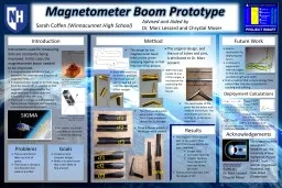
Method Future Work This magnetometer is approximately 4 cubic centimeters It was built and photographed by Chrystal Moser The magnetometer boom for CubeSat Sigma a South Korean satellite that UNH is building a magnetometer for has flaws that can be used to create a more effective boom to use ID: 409822

magnetometer boom sigma cubesat boom magnetometer cubesat sigma satellite design joints marc carbon fiber brass cf2 mechanism moser springy

Share:

Link:

Embed:

Download Presentation from below link

Download Presentation The PPT/PDF document "Introduction" is the property of its rightful owner. Permission is granted to download and print the materials on this web site for personal, non-commercial use only, and to display it on your personal computer provided you do not modify the materials and that you retain all copyright notices contained in the materials. By downloading content from our website, you accept the terms of this agreement.


Presentation Transcript

Slide1

Introduction

Method

Future Work

This magnetometer is approximately 4 cubic centimeters. It was built and photographed by Chrystal Moser.

The magnetometer boom for CubeSat Sigma, a South Korean satellite that UNH is building a magnetometer for, has flaws that can be used to create a more effective boom to use on future satellites.

A

magnetometer

is a device that measures the intensity and direction of magnetic fields.

A magnetometer needs to be held away from the spacecraft or satellite so that magnetic fields generated by the magnetometer’s carrier do not influence or alter the data.

The magnetometer boom is what holds the device away from the satellite.

The motivation behind the project is that the boom set to go up on CubeSat Sigma could be improved and used on future satellites.

A CubeSat Sigma that will be sent up with a magnetometer from UNH. Picture courtesy of Dr. Marc Lessard

.

Goals

Acknowledgements

Problems

C

reate a more compact design.

Make a sturdier boom that is stiffer and strong in multiple directions.

The current boom on CubeSat Sigma is too large.

The boom is strong in one direction but weak in another.

The design for the magnetometer boom relies on the pieces snapping together so that they are sturdy.

Build a mechanism for deploying the boom.

Continue to

experiment with

tab

edges

to

find

the best

possible

length and width.

A CubeSat is a satellite built of U’s. One U is a 10cm cube. These cubes are put together to house the instruments the satellite will carry.

CubeSat Sigma is 3U.

An example of a 3U CubeSat.

Krebs

, Gunter D. "CubeSat."

CubeSat

. 1996. Web. 22 July

2014.

This design is a modification of Dr. Marc

Lessard’s

original concept.

Sarah Coffen

(Winnacunnet High School)

Magnetometer Boom Prototype

Brass was used first as a test in principle.

The brass was not springy and did not hold the second part (

SPbr

) straight.

The

Magnetosphere Ionosphere Research Lab

, the University of New Hampshire, and Project SMART.

Advised and Aided by: Dr. Marc LessardChrystal Moser

Deployment Calculations

With the brass model of one of the hinges, a mechanism for extending the boom was fabricated.

Find a material that is more springy than carbon fiber that also is resistant to cracking and splitting.

A design for a boom deployment mechanism.

The next model of the joints for the boom was made of aluminium. The aluminium was not as springy or as strong as expected.

The third set of models was made of carbon fiber. It was a material chosen for its strength.

Three different models of the hinges were created.

Results

cf1

cf2

cf3

cf1

cf2

cf3

The support of the second part of the carbon fiber joints (

SPcf) was best in the parts that had:Longer tabsA smaller openingGreater distance from the end of the tube to the pin hole.The sturdiest joint was with the shape of cf2.

SPcf

SPbr

Advised and Aided byDr. Marc Lessard and Chrystal Moser

To deploy the boom, th

e main cable would have to be pulled approximately 1.4”.

R

pulley = 1/4”Cpulley = π/4”

π/4” = π/8” 2

π/8” x 3.5 turns ≈ 1.4”

When the boom extends cable will shorten by half the circumference of the pulley at each joint.

There are three joints that open 180o and one that opens 90o, so that is 3.5 turns of the joints.

"Blue Planet Wallpaper." - Space Wallpapers. Web. 22 July 2014

Thanks to:

Scott

Goelzer

(Coe-Brown Academy), and

Louis Broad

(

Timberlane

).