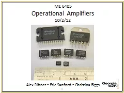
10212 Alex Ribner Eric Sanford Christina Biggs 1 Outline by Alex Ribner What is an Op Amp Ideal versus Real Characteristics Types of Op Amps Applications 2 Background ID: 714160
Download Presentation The PPT/PDF document "ME 6405 Operational Amplifiers" is the property of its rightful owner. Permission is granted to download and print the materials on this web site for personal, non-commercial use only, and to display it on your personal computer provided you do not modify the materials and that you retain all copyright notices contained in the materials. By downloading content from our website, you accept the terms of this agreement.
Slide1
ME 6405Operational Amplifiers10/2/12
Alex Ribner Eric Sanford Christina Biggs
1Slide2
Outlineby: Alex Ribner
What is an Op Amp?Ideal versus Real CharacteristicsTypes of Op AmpsApplications2Slide3
BackgroundOperational amplifiers (op-amps), use an external power source to apply a gain to an input signal.
Made of resistors, transistors, diodes and capacitors.Variety of functions such as: mathematical operations, perform buffering or amplify AC and DC signals.3Slide4
741 Op-Amp Schematic
differential amplifier
high-gain amplifier
voltage level shifter
output stage
current mirror
current mirror
current mirrorSlide5
Timeline1946 –patent for an op-amp using vacuum tubes.1953 –op-amps for sale
1961 – discrete IC op-amp1965 – successful monolithic op-amps1968 – uA7415Slide6
General Schematic
Some Op Amps have more than these 5 terminalsActive device! Requires power.6Slide7
Feedback
Closed loop configurations reduce the gain of the amplifier, but adds stability.Part of the output signal is applied back to the inverting input of the amplifier.Op amps use negative feedback.
Negative feedback helps to: overcome distortion and non-linearity, tailor frequency response, and stabilize circuit properties from outside influences such as temperature.
7Slide8
Behavior of an Op Amp
Achieves:Very high input impedance
Very high open loop
gain
V
ery
low output impedance.
In Three Steps:
Differential input stage, draws negligible amounts of input current enables assumption for ideal Op Amp properties.
Voltage gain stage, responsible for gaining up input signal and sending it to output stage.
Output stage, delivers current to op amp’s load.
8Slide9
‘Golden Rules’ of Ideal Op-Ampsby: Eric Sanford
These characteristics can be summarized with two ‘golden rules’:1 - The output attempts to do whatever is necessary to make the voltage difference between the inputs equal to zero (when used in a closed-loop design).2 - The inputs draw no current.9Slide10
Ideal Op-AmpCharacteristics:Gain, K = V
out / (V+-V-) = ∞Input impedance, Zin = ∞Input currents, i+
= i- = 0
Output impedance, Z
out
= 0
Unlimited bandwidth
Temperature-independent
V
out
+
-
Z
out
V
-
V
+
Z
in
i
-
= 0
i
+
= 0
K
10Slide11
Real Op-Amp
Characteristics (typical values):Gain, K = Vout
/ (V+-V-
) =
10
5
< K <
10
9
Input impedance, Z
in
=
10
6
(BJT), 109 - 1012
(FET)Input currents, i+ = i- = 10-12 – 10-8 AOutput impedance, Zout = up to 1000
Finite bandwidth, 1-20 MHzAll parameters change with temperature11Slide12
Ideal versus Real Op-Amps
ParameterIdeal Op-Amp
Real Op-Amp
Differential Voltage Gain
∞
10
5
- 10
9
Gain Bandwidth Product (Hz)
∞
1-20 MHz
Input Resistance (R)
∞
10
6
- 1012 ΩOutput Resistance (R)0
100 - 1000 ΩIdealReal
12Slide13
Saturation Voltages+ saturation:Vout
= Vsat+ ≈ Vcc+Linear Mode: Vout = K (V+- V-)
- saturation:Vout = V
sat
-
≈ V
cc
-
Note: v
d
= v
in
, v
0 = vout, vcc = source voltage13Slide14
Basic Op-Amp Typesby: Christina Biggs
InvertingNon-InvertingIntegratingDifferentialSumming14Slide15
Three Op Amp SetupsDifferential Input
2) Inverting Mode3) Non-inverting Mode
15Slide16
Non-Inverting Amplifier Analysis
Amplifies the input voltage by a constant
D
etermined
by voltage output
16Slide17
Derivation of Non-inverting Amplifier17
R1/(R1+R2)
Voltage
Divider Rule
V
-
=V
out
(R
1
/(R
1
+R
2
) )Vout=[Vin-Vout (R1/(R1+R2))] K
Vout=Vin/[(1/K)+ (R1/(R1+R2))]As discussed previously assuming, K is very large, we have:
Vout=Vin/(R1/(R1+R2))Vout=Vin (1+(R2/R1))
Vout=K(V+-V-)Slide18
Inverting Amplifier
virtual
ground
Amplifies and inverts the input
voltage
P
olarity
of the output voltage is opposite to
the
input
voltage
Determined
by
both
voltage input and output18Slide19
Derivation of Inverting Amplifier19
Vout=K(V+-V-)
V
-
=V
out
(R
in
/(R
in
+R
f
))+V
in
(Rf/(Rin+Rf))V-=(VoutRin+VinR
f)/(Rin+Rf)Vout=K(0-V-)Vout
=-VinRf/[(Rin+Rf)/K+(Rin)]Vout=-VinRf/RinSlide20
Op-Amp Integrator
Integrates the inverted input signal over
time
Magnitude of the output is determined by length of time voltage is present at
input
The longer the input voltage is present, the greater the output
20Slide21
Op-Amp Differentiator
Magnitude of output determined by the rate at which the applied voltage changes.
Faster change, greater output voltage
The resistor and capacitor create an RC network
21Slide22
Op-Amp Summing Amplifier
Scales the sum of the input voltages by the feedback resistance and input to produce an output voltage.
22Slide23
Op-Amp Differential Amplifier
If R
1
= R
2
and R
f
= R
g
:
Produces an output proportional to the difference of the input voltages
23Slide24
ApplicationsFilters,Strain Gages,PID Controllers,Converters,
Etc…24Slide25
PID Controllers25
Goal is to have V
SET
= V
OUT
Remember that V
ERROR
= V
SET
– V
SENSOR
Output Process uses V
ERROR
from the PID controller to adjust Vout such that it is ~VSETSlide26
Strain Gages26
Use a Wheatstone bridge to determine the strain of an element by measuring the change in resistance of a strain gauge
(No strain) Balanced Bridge R #1 =
R #2
(Strain) Unbalanced Bridge
R #1
≠
R #2Slide27
2nd Order Op-Amp Filters27
Three
2nd order filters: low pass, high pass, and
bandpass
. Slide28
ConclusionQuestions?
28Slide29
References[1] "What Is an Op Amp?" What Is an Op Amp?
National, n.d. Web. 25 Sept. 2012. <http://www.national.com/AU/design/courses/268/the02/01the02.htm>.[2] Student Lecture Fall 2010. Op-Amps… and why they are useful to us. [3] Student Lecture Fall 2011. What is an Op-Amp?[4] "Operational Amplifier." Wikipedia. Wikimedia Foundation, n.d. Web. 25 Sept. 2012. <http://en.wikipedia.org/wiki/Operational_amplifier>.
[5] "Op-Amp Basics."
Op-Amp Basics
.
N.p
.,
n.d.
Web. 27 Sept. 2012. <http://www.bowdenshobbycircuits.info/opamp.htm
>.
[6]
Jung, Walter G.
Op Amp Applications Handbook
. Burlington, MA: Newnes, 2006. Web. 26 Sept. 2012. <http://www.analog.com/library/analogDialogue/archives/39-05/op_amp_applications_handbook.html>.[7] "Operational Amplifiers."
Operational Amplifiers. N.p., n.d. Web. 25 Sept. 2012. <http://hyperphysics.phy-astr.gsu.edu/hbase/electronic/opamp.html>.29