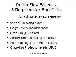
amp Regenerative Fuel Cells Enabling renewable energy Vanadium redox flow PolysulfideBromine flow Uranium based ZincBromide half redox flow All liquid regenerative fuel cells Ongoing Projects here in UIUC ID: 694226
Download Presentation The PPT/PDF document "NPRE 498 Energy Storage Redox Flow Batte..." is the property of its rightful owner. Permission is granted to download and print the materials on this web site for personal, non-commercial use only, and to display it on your personal computer provided you do not modify the materials and that you retain all copyright notices contained in the materials. By downloading content from our website, you accept the terms of this agreement.
Slide1
NPRE 498 Energy Storage
Redox Flow Batteries & Regenerative Fuel Cells
Enabling renewable energy
Vanadium redox flow
Polysulfide/Bromine flow
Uranium (!!!) based
Zinc/Bromide (half redox flow)
All liquid regenerative fuel cells
Ongoing Projects here in UIUC Slide2
NPRE 498 Energy Storage
Dated back to the 70’s with the 1973 oil crisis Examples: Fe(III)/Fe(II) in liquid (solvated ionic) form
Cr(III)/Cr(II) in liquid (solvated ionic) form Redox flow battery (history)Slide3
NPRE 498 Energy Storage
A Fe/Cr
Redox flow batterySlide4
NPRE 498 Energy Storage
The Vanadium Redox Pair
Anode (-)
V
2+
V
3+
+ e-
Cathode (+)
V
4+ V5+ + e-
Advantages:
no non-desired ionic mixture
No need for salt bridge
Slide5
NPRE 498 Energy Storage
Vanadium Redox Battery
SchematicSlide6
NPRE 498 Energy Storage
The VRB: the bipolar constructionSlide7
NPRE 498 Energy Storage
VRB: Real system Slide8
NPRE 498 Energy Storage
VRB: Performance
Cell voltage change vs time in a charge/discharge cycle,
current density was 40mA/cm2Slide9
NPRE 498 Energy Storage
VRB: Performance
Cell voltage change in different membranes vs time in a charge/discharge cycle,
current density was 37.5mA/cm2Slide10
NPRE 498 Energy Storage
VRB: Issues
Disadvantage:
Cost of vanadium (cost > $100/kWhr)
Energy density (~30 Whr/kg) Slide11
NPRE 498 Energy Storage
Regenerative Fuel Cells
Referring to a system or a single cell?
A Regenerative Fuel Cell SystemSlide12
NPRE 498 Energy Storage
Regenerative Fuel Cells
A regenerative Fuel Cell System in NASA Glenn Center
Fuel cell
ElectrolyzerSlide13
NPRE 498 Energy Storage
A Single Cell
Regenerative Fuel CellsSlide14
NPRE 498 Energy Storage
But there is a big catch:Hydrophobicity vs Hydrophilicity Conflicting requirement in two modes for a gas phase product/reactant combination
Regenerative Fuel CellsSlide15
NPRE 498 Energy Storage
Regenerative Fuel Cells
All liquid RFC
A bit like Redox flow battery
Potentially higher energy density
Kinetics is generally slower
Example, NaBH4/H2O2Slide16
NPRE 498 Energy Storage
Polysulfide/Bromine Flow Battery
How it works?
3NaBr+(
n
−1) Na
2
Sn
Na
Br
3
+nNa2Sn−1, n=2−4Slide17
NPRE 498 Energy Storage
Polysulfide/Bromine Flow Battery
The structure of a PSB battery: (a) anolyte tank; (b) catholyte tank; (c1, c2) magnetic pump; (d1, d2, d3, d4) tie-in; (e1, e2) end plate; (f1, f2, f3, f4, f5, f6) gasket; (g1, g2) electrode plate; (h1, h2) flow frame; (i) cation exchange membrane; (j) negative electrode; (k) positive electrode.
Slide18
NPRE 498 Energy Storage
Polysulfide/Bromine Flow Battery
Polarization curves (at 50% SOC) with different material: (♦,
) GF; (■, □) CF; ( upright triangles
) ACE; (●, ○) Co-ACE; and (
, inverted triangles
) Co-GF. Slide19
NPRE 498 Energy Storage
Polysulfide/Bromine Flow Battery
Discharge curves of ( u tri
) CF and ( inv tri
) ACE. (○) Cell open circuit voltage curve. (Line 1) positive half-cell potential and (line 2) negative half-cell potential. Slide20
NPRE 498 Energy Storage
Polysulfide/Bromine Flow BatterySlide21
NPRE 498 Energy Storage
Polysulfide/Bromine Flow BatterySlide22
NPRE 498 Energy Storage
Polysulfide/Bromine Flow Battery
Advantages
Low cost
Fast kinetics
Disadvantages
Cross-over
Poor stability