/
International Journal of Recent Development in Enginee International Journal of Recent Development in Enginee

International Journal of Recent Development in Enginee - PDF document

tatiana-dople
tatiana-dople . @tatiana-dople
Follow
387 views
Uploaded On 2015-05-04

International Journal of Recent Development in Enginee - PPT Presentation

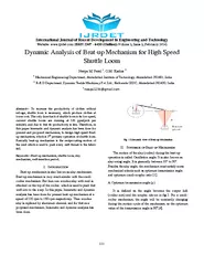
ijrdet com ISSN 2347 6435 Online Volume Issue February 201 111 Dynamic Analysis of Beat up Mechanism for High Speed Shuttle Loom Neepa M Patel GM Karkar Mechanical Engineering Department Ahmadabad Institute of Technology Ahmadabad 382481 India 2 R ID: 60729

ijrdet com ISSN 2347 6435

Share:

Link:

Embed:

Download Presentation from below link

Download Pdf The PPT/PDF document "International Journal of Recent Developm..." is the property of its rightful owner. Permission is granted to download and print the materials on this web site for personal, non-commercial use only, and to display it on your personal computer provided you do not modify the materials and that you retain all copyright notices contained in the materials. By downloading content from our website, you accept the terms of this agreement.


Presentation Transcript

International Journal of Recent Development in Engineering and Technology Website: www.ijrdet .com ( ISSN 2347 - 6435 (Online) ) Volume 2 , Issue 2 , February 201 4 ) 111 Dynamic Analysis of Beat - up Mechanism for High Speed Shuttle Loom Neepa M. Patel 1 , G.M. Karkar 2 1 Mechanical Engineering Department, Ahmadabad Institute of Technology, Ahmadabad - 382481, India. 2 R & D Department, Dy namic Textile Machinery Pvt. Ltd., Kathwada GIDC, Ahmadabad - 382430, India. 1 neepa1234@gmail.com Abstract — To increase the productivity of cloth es without selvage, shuttle loom is necessary, which produce clothes at lower cost. The only drawback of shuttle loom is its low speed, current shuttle looms are running at 120 ppm(pick per minute), and due to this its productivity is less. Therefore, in t his paper kinematic and dynamic analysis has been done for present and proposed mechanism, to design high speed Beat - up mechanism, which is 3 rd primary operation of shuttle loom. Basically beat - up mechanism is the reciprocating motion of the reed which is used to push every weft thread to the fabric fell . Keywords — Beat - up mechanism, shuttle loom, sley mechanism, weft insertion period. I. I NTRODUCTION Beat - up mechanism is also known as sley mechanism. Beat - up mechanism is very much similar with the crank - r ocker mechanism. But here one wooden sley with reed is attached on the top of the rocker, which is used to push that weft into to the warp. In this paper, kinematic and dynamic analysis has been done for present beat - up mechanism at a speed of 120 rpm to 1 80 rpm respectively. Then wooden sley is replaced by aluminum channel, and for that new proposed mechanism, kinematic and dynamic analysis has been done. Fig. 1 Schematic view of Beat - up Mechanism II. S YNTHESIS OF B EAT - UP M ECHANISM The motion of the sl ey (rocker) during the beat - up operation is called Oscillation angle. It is also known as sley swing angle. It is generally between 10° to 30°. Besides the sley angle, the mechanism must satisfy some mechanical criteria such as optimum transmission angle a nd optimum crank - coupler ratio [1]. A. Optimum transmission angle (µ) It is defined as the angle between the output link (rocker arm) and the coupler, shown in fig.2. For a crank - rocker mechanism, the angle will be constantly changing during the mot ion cycle of the mechanism, so the optimum value of the transmission angle is 90 0 [4]. International Journal of Recent Development in Engineering and Technology Website: www.ijrdet .com ( ISSN 2347 - 6435 (Online) ) Volume 2 , Issue 2 , February 201 4 ) 112 Fig . 2 . Transmission Angle of Crank - rocker Mechanism B . Optimum crank coupler ratio The ratio r/l, where r is the radius of the crank circle and l is the length of the crank arm, is called the sley eccentricity ratio (e). If the sley eccentricity is increased then the sley remains for longer time near its most backward position, and more time is available for the passage of the shuttle. But if the sley eccentricity increases many mechanical problems occur in loom. So, for this reason, mostly loom makers tend to avoid eccentricity ratio greater than about 0.3(particularly in shuttle loom) [3][4]. III . D ESIGN C ALCULATION FOR THE L INK L ENGTHS OF B EAT - UP M ECHANISM In this method, the link lengths (i.e. ) of a crank rocker mechanism are determine for a given sley angle ( á´ª ) and the transmission angle (µ). Here is an independent design parameter. And are three parameters calculate d from the below equations [1]. …(1) …(2) …(3) TABLE I B ASED ON M INIMUM T RANSMISSION A NGLE ( µ ) ( P LEASE R EFER L AST P AGE ) IV. K INEMATIC A NALYSIS FOR THE C RANK - R OCKER M ECHANISM As shown in Table no.I , mostly selection is done by the sley eccentricity ratio, bec ause for the smooth weaving operation, eccentricity ratio 0.3 should be taken by loom designers. After the dimensions of the beat - up mechanism are calculated, the position, velocity and acceleration are determined by using loop closer equation [5][6].Here current loom dimensions are selected for kinematic analysis, which are mentioned in T able no.II . TABLE II I K INEMATIC A NALYSIS OF C URRENT B EAT - UP M ECHANISMS µ=94° current loom á´ª =13.34° 0.065 m 0.445 m 0.578 m e = 0.15 A. Displacement, Angular Velocity and Angular Acceleration of Sley Mechanisms In this analysis, we have assumed that the weft insertion is completed during the period when the sley is in the“bckzone”betweenitsoriginl(mostbckwrd) position and one - half of its maximum displacement. The corresponding period is referred to as the insertion period [2] . As shown in fig.3.(a), the weft insertion period of current loom is 91°+(360 ° - 277°)=174°. International Journal of Recent Development in Engineering and Technology Website: www.ijrdet .com ( ISSN 2347 - 6435 (Online) ) Volume 2 , Issue 2 , February 201 4 ) 113 Fig.3 (a) Sley Displacement Fig.3 (b ) Sley Angular Velocity and Angular Acceleration V. D YNAMIC F ORCE A NALYSIS OF B EAT - UP M ECHANISM In order to design links and joints one must determine the worst loading conditions of each link and joint. In order to select the driving motor characteristics, input torque for the whole cycle is required. In such cases analytical methods suitable for numerical computation is utilized. After kinematic analysis of the beat - up mechanism, now using the bel ow equations,forces of each link has to be calculated [7]. Fig.4 Acceleration of the centers of gravity A. Free Body Diagram of Beat - up Mechanism The system is in dynamic equilibrium under the action of these forces. We would like to determine the input Torque and the joint forces. The free body diagrams of each moving link can be drawn and the equilibrium equations can be written Fig.5 Free body diagrams of Beat - up Mechanism 1 For link number 2 : ...(1) ...(2) ...(3) International Journal of Recent Development in Engineering and Technology Website: www.ijrdet .com ( ISSN 2347 - 6435 (Online) ) Volume 2 , Issue 2 , February 201 4 ) 114 2 For link number 3 : ...(4) ...(5) ...(6) 3 For link number 4 : ...(7) ...(8) ...(9) Hence, we obtain nine linear equations and nine unknowns (F l4x , F l4y , F 34x , F 34y , F 23x , F 23y , F l2x , F l2y and T 12 ). If a computer subroutine for the matrix solution is available, these equations can be s olved directly for the unknowns [8]. However, it is much simpler to solve equations (6) and (9) simultaneously for F 34y and F 34x and then solve for each unknown from the remaining equations. A= I 4  4 +m 4 g 4  a G4y cos(  4 ) - a G4x sin(  4 )  B= I 3  3 +m 3 g 3  a G3y cos(  3 ) - a G3x sin(  3 )   F 34x =  Aa 3 cos  3 +Ba 4 cos  4  /  a 3 a 4 sin(  3 -  4 )   F 34y =  Aa 3 sin  3 +Ba 4 sin  4  /  a 3 a 4 sin(  3 -  4 )   F 14x = - F 34x +m 4 a G4x  F 14y = - F 34y +m 4 a G4y F 23x = F 34x +m 3 a G3x F 23y = F 34y +m 3 a G3y F 12x = F 23x +m 2 a G2x F 12y = F 23y +m 2 a G2y T 2 = F 23y a 2 cos(  2 ) - F 23x a 2 sin(  2 ) + I 2  2 + m 2 g 2  a G2y sin(  2 ) - a G2x sin(  2 )    With the help of above equations, the crank torque and the beat - up force of current mechanism can be calculate.  Fig.6 Comparison of Beat - up Forces at different speed &weight VI. R ESULTS A ND D ISCUSSIONS Fig.7 (a) Present Loom with wooden Sley International Journal of Recent Development in Engineering and Technology Website: www.ijrdet .com ( ISSN 2347 - 6435 (Online) ) Volume 2 , Issue 2 , February 201 4 ) 115 Fig.7 (b) Proposed Loom with Aluminum - channel Sley TABLE III II C OMPARISON B ETWEEN P RESENT AND P ROPOSED L OOM ) ( P LEASE R EFER L AST P AGE ) VII. C ONCLUSIONS In order to understand the working of beat - up mechanism and motion of sley, kinematic and dynamic analysis of current beat up mechanism has been carried out a t a speed of 120rpm, also it has been done for 180 rpm respectively. It was found that due to high speed of 180 rpm various force in the beat u p mechanism got increased, which could result in mechanical breakage. To reduce the forces the wooden - sley weighing 80 kg is replaced by the aluminum channel weighing 14 kg; here the proposed mechanism then analyzed for dynamic loading conditions, due to t his the forces are reduced. So, the proposed mechanism can run easily at 180rpm without changing the driving motor characteristics. Here in proposed beat - up mechanism, the dimensions of linkages are to be taken as it is. References [1] R. Eren and A. Aydemir. “ An Approach to Kinematic Design of Four - bar S leyDriveMechnismsinWeving” , The Jo urnal of The Text.Inst., Turkey , 2004. P 193 - 205 . [2] YoujingWngndHuiSun,” computer Aided Analysis of L o om Bea ting - upMechnism” , The Journal of The Text.Inst., 1998. P 631 - 634. [3] H.I.Celik & M.Topalbekiroglu, ” Kinematic analysis and synthesis of the beat up mec hnismforHndmdeCrpetloom” , The Journal of The Text.Inst., Turkey, 2010.p.882 - 889. [4] H.I.Celik &M.Topa lbekiroglu.” Kinematic analysis of the beat up mech ani smforhndmdecrpetlooms” , Indian Journal of Fibre & Textile Research,(Vol.34),Turkey.2009.pp. 129 - 136. [5] K.J.Wldron&G.L.Kinzel.”Kinemtic, Dyn amics and Design of mchinery”, 2 n d edition,Library of Congress Cataloging - in - Publication Data,2004.Chap.5 [6] Jac kT.Kimbrell,’KinemticAnlysisndSynthesis’,Singpore, 1991 Chap.3,4.p.69 - 71,96 - 99. [7] JohnJ.Uicker,JR,GordonR.Pennock,JosephE.Shigley,‘Theory ofMchinesndMechnisms’,3 rd edition, Oxford University Press,2011.p.466 [8] R.L.Norton,‘Kinemt icsndDynmicsofMchinery’,1 st edition, Worcester, Massachusetts, U.S.A.2010.p.555. International Journal of Recent Development in Engineering and Technology Website: www.ijrdet .com ( ISSN 2347 - 6435 (Online) ) Volume 2 , Issue 2 , February 201 4 ) 116 TABLE IV B ASED ON M INIMUM T RANSMISSION A NGLE ( µ ) Links µ=50° µ=60° µ=74° á´ª =10° á´ª =20° á´ª =30° á´ª =10° á´ª =20° á´ª =30° á´ª =10° á´ª =20° á´ª =30° 67.37 132.02 190.76 66.99 128.60 178.40 65.0 106.66 73.132 105.42 209.98 312.91 135.44 269.81 402.14 245.30 488.73 728.51 773.80 760.65 737.38 769.05 740.96 689.46 741.12 614.62 282.72 e= 0. 63 0.63 0.60 0.49 0.47 0.44 0.26 0.22 0.10 TABLE V II C OMPARISON B ETWEEN P RESENT AND P ROPOSED L OOM Sr. Present Loom (fig.7.a) Proposed Loom (fig.7.b) 1. Beat - up F orce is 520 N when wooden - sley weight is 40kg at 120 rpm Beat - up Force is 135 N when aluminum - sley weight is 7kg at 120 rpm 2. Beat - up Force is 1160 N when wooden - sley weight is 40kg at 180 rpm Beat - up Force is 300 N when aluminum - sley weight is 7kg at 180 rpm 3. Crank shaft torque is 40 N - m when wooden - sley weight is 40kg at 120 rpm Crank shaft torque is 16 N - m when aluminum - sley weight is 7kg at 120 rpm 4. Crank shaft torque is 92 N - m when wooden - sley weight is 40kg at 180 rpm Crank shaft torque is 35 N - m when aluminum - sley weight is 7kg at 180 rpm 5. Wooden sley weight = 70kg Aluminum Channel weight = 11kg 6. Shuttle box weight = 5*2=10kg Shuttle box weight = 1*2 =2kg 7. Total weight of sley =80kg Total weight of sley = 14kg (1kg for woo den plate)