/
Lesson 4 Propagation, Antennas, Feed Lines Lesson 4 Propagation, Antennas, Feed Lines

Lesson 4 Propagation, Antennas, Feed Lines - PowerPoint Presentation

tatiana-dople
tatiana-dople . @tatiana-dople
Follow
358 views
Uploaded On 2018-03-10

Lesson 4 Propagation, Antennas, Feed Lines - PPT Presentation

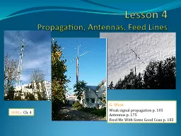
ARRL Ch 4 G West Weak signal propagation p 105 Antennas p 175 Feed Me With Some Good Coax p 183 The Sky Above Ionosphere Weather 30 mi 260 mi ISS 414 mi Learn your D E Fs ID: 645880

antenna mhz radio signals mhz antenna signals radio uhf vhf meter meters propagation antennas ionosphere swr power coax signal frequency inches 300

Share:

Link:

Embed:

Download Presentation from below link

Download Presentation The PPT/PDF document "Lesson 4 Propagation, Antennas, Feed Lin..." is the property of its rightful owner. Permission is granted to download and print the materials on this web site for personal, non-commercial use only, and to display it on your personal computer provided you do not modify the materials and that you retain all copyright notices contained in the materials. By downloading content from our website, you accept the terms of this agreement.


Presentation Transcript

Slide1

Lesson 4Propagation, Antennas, Feed Lines

ARRL

: Ch. 4

G. West

Weak signal propagation

p

. 105

Antennas

p

. 175

Feed Me With Some Good Coax

p

. 183Slide2

The Sky AboveIonosphereWeather

30 mi.

260 mi

-ISS

414 miSlide3

Learn your D, E, F’s T3A11 The ionosphere is the part of the atmosphere that enables the propagation of radio signals around the world.Each reflection is called a hop.

3

Ionosphere and its layers

30 to 260 milesSlide4

Ionosphere LayersSlide5

Absorption Slide6

6T5C07 T3A07 Radio waves is the usual name for electromagnetic waves that travel through space.Radio WavesSlide7

RADIO WAVES• Electromagnetic radiation comprises both an Electric and a MagneticField.• The two fields are at right-angles to each other and the direction ofpropagation is at right-angles to both fields.• The Plane of the Electric Field defines the Polarization of the wave.MagneticField, HElectricField, EX

YSlide8

8Vertical and Horizontal PolarizationT9A02 The electric field of vertical antennas is perpendicular to the Earth.

8

H & V Polarized Antennas

T3A04

Polarization often becomes random as a radio wave travels through the ionosphere.Slide9

VHFUHF

Very High Frequency

Ultra High Frequency

30 – 300 MHz

300 – 3000 MHz

FM

Freq Range?

Mode for

repeaters

FM

Meaning

2 meter

frequency range

144 – 148 MHz

70 cm

frequency range

420 – 450 MHz

70 cm simplex

calling frequency

446.000 MHz

QuizSlide10

 VHF  

UHF


30 MHz


300 MHz


CHP


420 MHz

70 cm

450 Mhz


FRS/GMRS


50 MHz

6 Meters

54 MHz


TV


88

FM


Broadcast

108

902 MHz

33 cm

928 MHz

TV


Aviation


Aviation Cell Phone Military 1240 MHZ23 cm1300 MHz144 MHz2 Meters148 MHz  Municipal                                           219 MHz1.25 Meters225 MHz                          300 MHz  3000 MHz  Technician class home range Technician class home range6 meters the un-predictable bandLine of sight communicationsLine of sight communicationsSuited for repeater operationSuited for repeater operation70 cm suited for mobile and portableFM and digital modes.  Suited for mobile and portable comm. 2 mtr SSB and CW at lower band edge Satellite and EME Satellite and EME 

VHF & UHFSlide11

T3C10 The distance at which radio signals between two points are effectively blocked by the curvature of the Earth, is the radio horizon.VHF & UHF radio signals will generally travel “line of sight.”VHF & UHF radio signals are blocked by the curvature of the Earth.

T3C11

VHF and UHF radio signals usually travel somewhat farther than the visual line of sight distance between two stations because the Earth seems less curved to radio waves than to light.

11

VHF and UHF Radio Waves

1.23

x

h

Miles feetSlide12

Reflections UHF signals are short enough in wavelength to permit bouncing around inside buildings and penetrating of walls.T3A02 UHF signals are often more effective from inside buildings than VHF signals as the shorter wavelength allows them to more easily penetrate the structure of buildings.Slide13

Two Meter Ball in the Side PocketT3A05 When using a directional antenna, your station might be able to access a distant repeater if buildings or obstructions are blocking the direct line of sight path by finding a path that reflects signals to the repeater.13

Directional Antenna can be used to bounce signal to reach repeater blocked by buildingSlide14

MultipathT3A10 Error rates are likely to increase on VHF or UHF data signals propagated over multiple paths.T3A01 Should another operator reports that your stations 2 meter signals were strong just a moment ago, but now they are weak or distorted, try moving a few feet, as random reflections may be causing multi-path distortion.

T3A06 Rapid fluttering from multipath while moving is called picket-fencingSlide15

DuctingT3C08 Temperature inversions in the atmosphere causes "tropospheric ducting".15

Tropospheric

DuctingSlide16

Tropospheric ScatterT3C06 Tropospheric scatter is responsible for allowing over-the-horizon VHF and UHF communications to ranges of approximately 300 miles on a regular basis.Tropospheric16Slide17

Knife-Edge DiffractionT3C05 The term "knife-edge" propagation refers to signals that are partially refracted around solid objects exhibiting sharp edges.

17Slide18

Sporadic ET3C04 Sporadic E propagation is most commonly associated with occasional strong over-the-horizon signals on the 10, 6, and 2 meter bands. VHF band.T3C02

When VHF signals are being received from long distances these signals are being refracted from a sporadic E layer.Slide19

Sporadic EUp to 1500 mi.300 mi +Slide20

DL2YMRSporadic E 10 meters 2010Slide21

Meteor ScatterT3C07 The 6 meter band is best suited to communicating via meteor scatter.Leonids and Geminids meteor showers provide these conditions Slide22

AuroraT3C03 A characteristic of VHF signals received via auroral reflection is that the signals exhibit rapid fluctuations of strength and often sound distorted.22

Incoming signals from a distant station heard hundreds of miles away will sound fluttery and distorted by auroral bounceSlide23

HFHigh Frequency3 – 30 MHzFreq Range?

Most common

Voice Mode

Meaning

SSB

SSB

Bandwidth

3 kHz

Quiz

QuizSlide24

HF HF


3 MHz


3.5 MHz

80 Meters

4 MHz


5.33 MHz

60 Meters

5.4035 MHz


7 MHz

40 Meters

7.3 MHz

Lower sideband


Upper sideband


10.1 MHz

30 Meters

10.150 MHz


14 MHz

20 Meters

14.350 MHz


17 Meters


15 Meters


       12 Meters   CB 28 MHz10 Meters29.7 MHz30 MHz  Primary General and Extra Class privledgesLimited Technician privilegesSSB on 10 M CW on 40 and 15 meters Long distance communications Large antennas. Day to night from upper to lower freq.60 and 30 meter special restrictionsSolar activity critical T3C09 During daylight hours is generally the best time for long-distance 10 meter band propagation via the F layer.Slide25

Learn your D, E, F’s T3A11 The ionosphere is the part of the atmosphere that enables the propagation of radio signals around the world.Each reflection is called a hop.

25

Ionosphere and its layers

30 to 260 milesSlide26

26 T3A09 “Skip” signals from the ionosphere become elliptically polarized.Skip happens when signals refract and reflect off the ionosphere. DX stations 1000 miles away come booming in. Every 30 seconds signal goes from strong to weak and back. Caused by random, ever changing polarization of the original signal.Either vertical or horizontal polarized antennas can be used.

26

SkipSlide27

Ionosphere from spaceSlide28

IonosphereSlide29

ISS ImageSlide30

What is the greatest influence on propagation, especially HF?Charged ionosphereSolar radiation

Uncharged ionosphereSlide31

Solar indiciesCoronal Mass Ejections (CME)Sun Spot activity - approximate 11 year cycleSolar Flux, (Index) SFI : is a measure of the radioenergy emitted from the sun

. Values 50 to 300. //the higher the better

A index, related to K in an averaging, values

0 t0 400

K index, disturbances in the horizontal component of earths magnetic field. Values 0 to 9

http://

dx.qsl.net

/propagation/Slide32

Today’s SFIHighs for Cycle 24 Flux: 190 - 24 Sep 2011 Sunspots: 208 - 9 Nov 2011 Summary for the past 24 hours:No space weather storms were observed for the past 24 hours.

Lower A index means better propagation.

K-Index -

Falling numbers mean improving conditions and better propagation

Solar Flux Index (SFI) - Higher numbers mean better propagation.Slide33

33AntennasT9A03 A simple dipole mounted so the conductor is parallel to the Earth's surface is a horizontally polarized antenna.33

Three element beam

Simple DipoleSlide34

34Size MattersT9A09 The approximate length of a 6 meter 1/2-wavelength wire dipole antenna in inches is ?

34

Six Meter ½ Wavelength Dipole

T9A10

The strongest radiation from a half-wave dipole antenna

in free space is broadside to the antenna.

6 meters / 2 = 3

m

(1 meter

< 40 inches)

40 inches X 3

= < 120 inches

112 inches

6

50

112

236

T9A09Slide35

35T9A08 The approximate length of a quarter-wavelength vertical antenna for 146 MHz in inches is?35

19

Radiation Pattern of an Antenna Changes as Height Above Ground is Varied

2 meters

/4 =

½ meter

(1 meter

< 40 inches)

<

20 inches

112

50

19

12

T9A08Slide36

Antennas on handheld radiosT9A04 The typical “rubber duck antennaDoes not receive or transmit as wellas a full size ground-plane antennaT9A07 When transmitting frominside of a vehicle your signal may

be as much as 10 to 20 times weaker

than from an outside mobilea

ntenna.

Rubber duckSlide37

Decibel, The unit measure for gaindB = 10 log (p0wer ratio)Just remember that for every double, or half change in power, there is a 3 dB change. Increase or decrease depending on the direction of change.(I rely on my finger calculator.)Example 1. What is the approximate amount of change in dB of a power increasefrom 5 watts to 10 watts?3 db

Example 2. What is the approximate amount of change in dB, from a power

decrease from 12 watts to 3 watts?

6 dB

Example 3. What is the approximate amount of change in dB, of a power increasefrom 20 watts to 200 watts?

10 dBSlide38

Directional AntennasT9A01 A Beam Antenna, or Yagi, is an antenna thatdirects the signal in one direction.T3A03 Horizontal directional antennas are

Normally used for weak signal CW and SSBo

n VHF and UHF

At the higher UHF frequencies, dish antennas are commonly used.Slide39

39GainT9A11 The gain of an antenna is the increase in signal strength in a specified direction when compared to a reference antenna.Measured in dB

39

Isotropic Radiator Pattern

“Gain” of an antenna

dBi

= gain reference to an isotropic antenna

dBd

= gain reference to a dipole antennaSlide40

Radiation PatternAzimuth patternSlide41

Radiation PatternSlide42

42Directional antennasT9A01 A beam antenna concentrates signals in one direction42

A Beam Antenna – The Yagi AntennaSlide43
Slide44

44Feedlines

44

Copper Wire

Outside Insulation

Mesh

Insulation

T9B01

It is important to have

a low

SWR

in an antenna system that uses coaxial cable

feedline

to provide efficient transfer of power and reduce losses.

T9B02

50 ohms is the impedance

of the most commonly used coaxial cable in typical amateur radio installations.

T9B03

Coaxial cable is used

more often t

han any other

feedline

for amateur radio antenna systems because it is easy to use and requires few special installation considerations.Slide45

45Not all coax is the sameT9B10 Electrical differences exists between the smaller RG-58 and larger RG-8 coaxial cables in that RG-8 cable has less loss at a given frequency.

45

Coax Type Size @ 100 MHz @ 400 MHz

RG-58U Small

4.3 dB

9.4 dB

RG-8X Medium 3.7 dB 8.0 dB

RG-8U Large

1.9

dB

4.1

dB

RG-213 Large

1.9

dB

4.5

dB

Hardline

Large, Rigid

0.5

dB

1.5

dB

Coax Cable Type, Size, and Loss per

100

feet

T9B11

The lowest loss

feedline

at VHF and UHF is an Air-insulated hard line.

.Slide46

SWR Standing Wave RatioSWR is determined by the proportions of forward and reflected power.T7C03 In practice it is a measure of how well antenna and feed line impedances are matched.If there is no reflected power, the SWR is 1 to 1. SWR = 1:1T7C04

SWR of 1:1 is a perfect match.

T7C06 SWR greater that 1:1 shows a degree of mismatch.

T7C05 SWR greater than 2:1 may cause the transmitter’s protective circuits to reduce output power.Slide47

What causes SWR?Antennas that are too short or too long.Faulty feedline or connectors.T9B09 Erratic SWR sometimes indicates a loose connector. PF is the forward RF power PR is the reflected RF power

P

F

+ √

P

R

P

F

-

P

R

SWR =Slide48

48How to Correct High SWRT9B04 An antenna tuner matches the antenna system impedance to the transceiver's output impedance.

48

Palstar 1500 Watt Auto-Tuner

MFJ-994B 1500 Watt Auto-Tuner

Icom 7000 with LDG 7000 Auto-Tuner

MFJ-971 Portable QRP 200 Watt Tuner

Miracle QPak 50 Watt Manual Tuner

#1 Correct any physical problemsSlide49

49Feedline ConnectorsT9B05 As the frequency of a signal passing through coaxial cable is increased the loss increases.

The Higher the frequency the greater the loss

T9B06

A Type N connector is most suitable for frequencies above 400 MHz?

T9B07 PL-259 type coax connectors are commonly used at HF frequencies.

49

BNC, Type N, and PL 259 ConnectorsSlide50

50Care and feeding of coax and connectors.T9B08 Coax connectors exposed to the weather should be sealed against water intrusion to prevent an increase in feedline loss.

Never buy cheap coax, connectors, or adapters

50

Make sure all coax connections are tight to help minimize interference

Don’t kink, crush, twist, crimp, mangle, contort, distort or otherwise

fubar

your coax. Slide51

Study for this WeekStudy flash cards www.hamexam.org73Tom and Jack

Lesson 1

T1B

T3B

T8A

Lesson 2

T1A

T1C

TID

T1E

T1F

Lesson 4

T3A

T3C

T9A

T9B

T7C

Lesson 5

T4A

T4B

T7A

T7B

T8D

Lesson 6

T5A

T5B

T5C

T5D

T6A

T6B

T6C

T6D

T7D

Lesson 3

T2A

T2B

T2C

T8B

T8C

Lesson 7

T0A

T0B

T0C

Radio

Fundamentals

Rules &

Regs

.

Comm.

w

/

Others

Antennas

Propagation

Equipment

Electricity

Safety