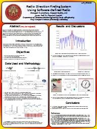
/
Light Enhancement and Direction Control Using Bowtie Antenna Arrays Light Enhancement and Direction Control Using Bowtie Antenna Arrays

Light Enhancement and Direction Control Using Bowtie Antenna Arrays - PowerPoint Presentation

margaret
margaret . @margaret
Follow
65 views
Uploaded On 2023-11-08

Light Enhancement and Direction Control Using Bowtie Antenna Arrays - PPT Presentation

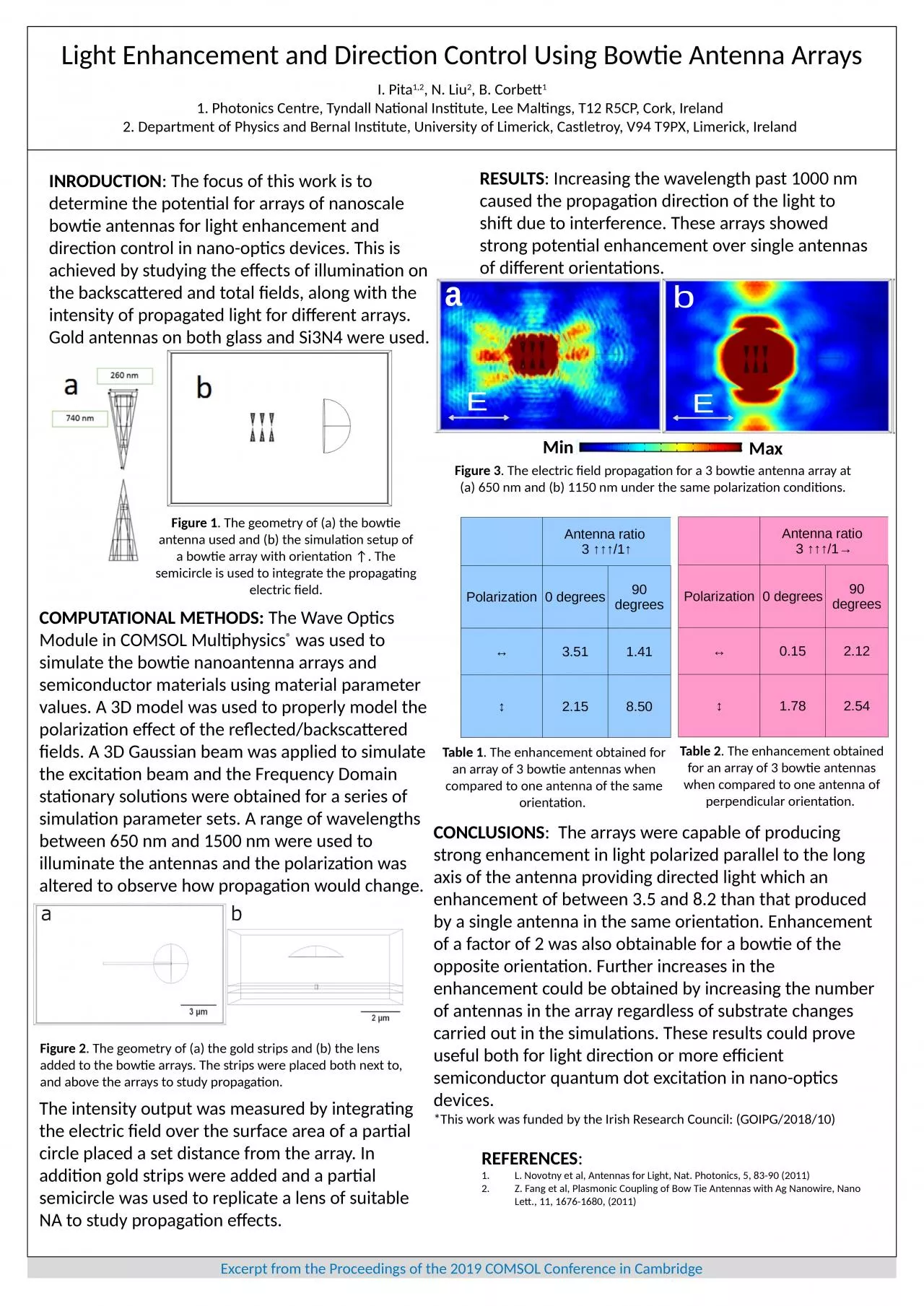
I Pita 12 N Liu 2 B Corbett 1 1 Photonics Centre Tyndall National Institute Lee Maltings T12 R5CP Cork Ireland 2 Department of Physics and Bernal Institute University of Limerick ID: 1030738

antennas bowtie light enhancement bowtie antennas enhancement light antenna arrays array orientation propagation direction obtained figure strips electric polarization

Share:

Link:

Embed:

Download Presentation from below link

Download Presentation The PPT/PDF document "Light Enhancement and Direction Control ..." is the property of its rightful owner. Permission is granted to download and print the materials on this web site for personal, non-commercial use only, and to display it on your personal computer provided you do not modify the materials and that you retain all copyright notices contained in the materials. By downloading content from our website, you accept the terms of this agreement.


Presentation Transcript

1. Light Enhancement and Direction Control Using Bowtie Antenna ArraysI. Pita1,2, N. Liu2, B. Corbett11. Photonics Centre, Tyndall National Institute, Lee Maltings, T12 R5CP, Cork, Ireland 2. Department of Physics and Bernal Institute, University of Limerick, Castletroy, V94 T9PX, Limerick, Ireland INRODUCTION: The focus of this work is to determine the potential for arrays of nanoscale bowtie antennas for light enhancement and direction control in nano-optics devices. This is achieved by studying the effects of illumination on the backscattered and total fields, along with the intensity of propagated light for different arrays. Gold antennas on both glass and Si3N4 were used.COMPUTATIONAL METHODS: The Wave Optics Module in COMSOL Multiphysics® was used to simulate the bowtie nanoantenna arrays and semiconductor materials using material parameter values. A 3D model was used to properly model the polarization effect of the reflected/backscattered fields. A 3D Gaussian beam was applied to simulate the excitation beam and the Frequency Domain stationary solutions were obtained for a series of simulation parameter sets. A range of wavelengths between 650 nm and 1500 nm were used to illuminate the antennas and the polarization was altered to observe how propagation would change.The intensity output was measured by integrating the electric field over the surface area of a partial circle placed a set distance from the array. In addition gold strips were added and a partial semicircle was used to replicate a lens of suitable NA to study propagation effects.RESULTS: Increasing the wavelength past 1000 nm caused the propagation direction of the light to shift due to interference. These arrays showed strong potential enhancement over single antennas of different orientations.Antenna ratio 3 ↑↑↑/1↑Polarization0 degrees90 degrees↔3.511.41↕2.158.50CONCLUSIONS:  The arrays were capable of producing strong enhancement in light polarized parallel to the long axis of the antenna providing directed light which an enhancement of between 3.5 and 8.2 than that produced by a single antenna in the same orientation. Enhancement of a factor of 2 was also obtainable for a bowtie of the opposite orientation. Further increases in the enhancement could be obtained by increasing the number of antennas in the array regardless of substrate changes carried out in the simulations. These results could prove useful both for light direction or more efficient semiconductor quantum dot excitation in nano-optics devices. *This work was funded by the Irish Research Council: (GOIPG/2018/10)  REFERENCES:L. Novotny et al, Antennas for Light, Nat. Photonics, 5, 83-90 (2011)Z. Fang et al, Plasmonic Coupling of Bow Tie Antennas with Ag Nanowire, Nano Lett., 11, 1676-1680, (2011)Figure 2. The geometry of (a) the gold strips and (b) the lens added to the bowtie arrays. The strips were placed both next to, and above the arrays to study propagation.Figure 3. The electric field propagation for a 3 bowtie antenna array at (a) 650 nm and (b) 1150 nm under the same polarization conditions.Table 1. The enhancement obtained for an array of 3 bowtie antennas when compared to one antenna of the same orientation. Table 2. The enhancement obtained for an array of 3 bowtie antennas when compared to one antenna of perpendicular orientation. Figure 1. The geometry of (a) the bowtie antenna used and (b) the simulation setup of a bowtie array with orientation ↑. The semicircle is used to integrate the propagating electric field.Excerpt from the Proceedings of the 2019 COMSOL Conference in CambridgeAntenna ratio 3 ↑↑↑/1→Polarization0 degrees90 degrees↔0.152.12↕1.782.54MinMaxabEE