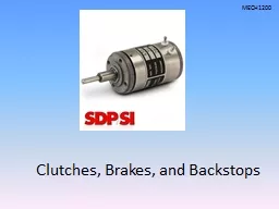
/
Magtrol Hysteresis Brakes  Clutches Users Manual As current is applied to the coil a magnetic Magtrol Hysteresis Brakes  Clutches Users Manual As current is applied to the coil a magnetic

Magtrol Hysteresis Brakes Clutches Users Manual As current is applied to the coil a magnetic - PDF document

tatiana-dople
tatiana-dople . @tatiana-dople
Follow
679 views
Uploaded On 2015-01-15

Magtrol Hysteresis Brakes Clutches Users Manual As current is applied to the coil a magnetic - PPT Presentation

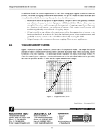
The rotor located within the air gap becomes magnetized Due to its speci64257c hysteresis properties the rotor resists movement creating a braking torque or clutch linkage between the pole structure and rotor The transmitted torque remains constant ID: 31337

The rotor located within

Share:

Link:

Embed:

Download Presentation from below link

Download Pdf The PPT/PDF document "Magtrol Hysteresis Brakes Clutches User..." is the property of its rightful owner. Permission is granted to download and print the materials on this web site for personal, non-commercial use only, and to display it on your personal computer provided you do not modify the materials and that you retain all copyright notices contained in the materials. By downloading content from our website, you accept the terms of this agreement.


Presentation Transcript

INTRODUCTIONThank you for selecting Magtrol Hysteresis Devices for your torque control application. We are condent that you will appreciate the quality that we build into our products and the years of superior performance they will provide you.Unlike many other torque control devices, Magtrol Hysteresis Brakes and Clutches provide absolutely and operate without any physical contact of interactive members. As a result, with the exception of shaft bearings, there are virtually Because hysteresis devices are often confused with magnetically actuated friction, magnetic particle, and Eddy-current devices, their operating characteristics and performance are often misunderstood. The following information is given to assist you in understanding these unique devices so that you can derive the maximum benet from their use.OPERATIONA hysteresis brake or clutch is made up of two primary members, the pole structure and the rotor, which interact magnetically to produce a braking or clutching force. The pole structure—which is made up of an inner pole, an outer case, and a coil—form the xed member of a brake assembly or the driven member of a clutch assembly. The geometry of the pole structure parts is such that they Rotor & HubCaseShaftMounting HoleMounting SurfaceBearings Figure 1. Hysteresis BrakeHysteresis Brakes and Clutches A slight Eddy-current effect is present in a hysteresis brake or clutch. While full braking torque is possible independent of slip speed, Eddy-current effects can increase the dynamic braking torque over a static calibrated value by as much as 7% to 8% per 1000 rpm increase in speed. (2% typical on smallest brake, 7% to 8% typical on largest.) 2 air gap. The rotor, located within the air gap, becomes magnetized. Due to its specic hysteresis properties, the rotor resists movement, creating a braking torque (or clutch linkage) between the pole structure and rotor. The transmitted torque remains constant and smooth as the rotor is forced to rotate within the air gap and will respond to increases and decreases in coil current with corresponding increases and decreases in torque. Though a slight Eddy-current effect is present in a hysteresis device, full rated torque can be provided independently of slip speed.Under normal operating conditions, the magnetic orientation of the rotor is constantly being realigned dynamic conditions the removal of coil current, and/or changes in coil current, result in a smooth transition from one torque level to the next. Under certain operating conditions, however, it is possible to set up a salient pole condition on the brake rotor which can result in “Cogging Torque” (sometimes referred to as torque ripple). Cogging torque is an inherent characteristic of a hysteresis brake which in most instances can be avoided and/or controlled so as to not be an objectionable part of your tension control scheme. This condition is described in detail under Section 7.0 – Cogging TorqueINSTALLATIONPrior to installation and the application of power to the unit, please verify that rotation is smooth and free. Should any abnormality be observed, please read Magtrol Hysteresis Brakes will perform equally well regardless of physical orientation. A solid double extended through-shaft is provided to facilitate coupling to either side of the brake. Because the brake employs a rotating element on one end (drag cup or rotor), surface mounting of the brake is only possible on the side opposite this rotating element. Surface mounting provisions are provided as standard on all brakes except the HB-840 and HB-3500 series. These brakes require the use of a rotating element on both ends and are therefore only available in a base-mounted conguration. On all other brakes, optional pillow blocks are available for mounting but are provided only when specically ordered. Mounting bases and pillow blocks, when ordered, are secured to the brake prior to shipment. Mounting hardware for afxing the base or pillow block to your structure is not provided. If Magtrol pillow blocks are not used for mounting, hardware of sufcient thread size and length will have to be obtained in the eld for surface mounting (see http://www.magtrol.com/ on Magtrol’s web site for thread size, thread depth, and bolt circle dimensions).Although intended for coupled service, moderate overhung loads can be tolerated, depending on such operating characteristics as speed, weight and location of the load’s center of gravity. Care should be taken to assure proper shaft alignment and couplings should be of proper size and exibility to adequately protect bearings from undue stress and shock loading. Rigid couplings which do not compensate for slight misalignment and shaft offset are not recommended. 3 Note:Small radial and axial loads can be tolerated. Please contact factory for further information regarding application assistance. Care must be taken to ensure proper shaft alignment.Note:Couplings of proper size and flexibility must be utilized to and shaft offset are not recommended.Magtrol Hysteresis Brakes are DC-powered devices. The amount of braking torque transmitted by the brake is proportional to the amount of current owing through the brake coil. The direction of current ow (polarity) is of no consequence to the operation of the brake, however, the normal convention of red wire = V+ and black wire = V– should be observed for consistency of operation especially on MHBs (Matched Brakes) and calibrated brake designs. For proper torque regulation, especially in an open loop system, a DC supply with stable current regulation (Magtrol model 5211 power supply capable of ±1% of full scale or equivalent) is recommended. This will help to diminish torque drift attributable to changes in coil temperature, changes in line voltage, etc. which would Before connecting the brake leads to the DC power source, check to make certain that the voltage setting of the power supply is in the range of the nominal coil voltage as indicated on the brake decal. With power supply off and voltage or current adjustments on their lowest settings, connect brake leads to power supply. Make certain to secure and insulate all electrical connections according to approved methods and standards prior to application of power. Your brake should now be ready for use. A braking torque will be felt as soon as current is applied to the brake coil and will increase in magnitude as coil current is increased. The maximum level of torque attainable will vary from one brake to another, however, Magtrol guarantees that every brake it manufactures will meet or exceed rated torque at rated current. Whenever possible, current to the brake should only be decreased and/or turned off while the brake shaft is being rotated. Shutting down the power supply while the brake is in a stationary position will leave a salient pole on the brake rotor which will manifest itself in the form of a low level cogging torque (see Section 7.0 – Cogging Torque 4 Because Magtrol Hysteresis Brakes and Clutches rely purely on magnetic action working through an air gap to develop torque, there are no active components in contact and virtually no wear except for the normal wear of shaft bearings. Therefore, other than occasional bearing replacements, there torque should be experienced whenever current is applied to the brake coil. Most abnormal operating characteristics are the result of interruptions of current ow to the brake coil. This can be due to faulty power supplies, bad connections, shorted lead wires, and shorted or open brake coils. Anytime abnormal characteristics such as irregular torque, loss of torque or loss of repeatability is experienced, each of these factors should be examined as a possible cause. One exception is the cogging condition, which is often misdiagnosed as a defective brake. This condition, however, does not represent a defective part and if inadvertently set up, can be easily removed in the eld by the reapplication of brake current and a reduction of the current level as the brake is being rotated. This procedure will restore the smooth operating characteristics of the brake.COGGING TORQUEIt is important to note that the presence of cogging torque does not represent a defective hysteresis brake or clutch. By understanding the operation of these devices, precisely controlled, absolutely smooth torque can be obtained at any operating speed and torque level. It is also important to note, however, that under certain circumstances, a cogging condition can be set up on any hysteresis device. While these circumstances are generally avoidable, it will be important for you to note that if a cogging condition has been inadvertently set up on a brake or clutch, it is easily removed PoleCaseRotor AssemblySSSNNNNS SN Figure 2. Stator Tooth StructureThe salient poles, which cause the cogging phenomenon, are most often the result of having removed brake current from the device while its rotor was in a stationary position. When this is done, the rotor, being comprised of a permanent magnet material, retains a magnetic orientation forming salient poles beneath each of the tooth combinations located in the pole structure. Rotation of the brake shaft in this state will result in a bumpy feeling, or cogging effect, as the salient poles on the rotor pass from one stator tooth to the next, even when no power is applied to the coil.There are several methods of control sequencing that will prevent the establishment of salient poles and/or minimizing their strength so as to reduce the amount of cogging torque they will present. 5 2nd Edition Rev A – October 2019avoided, or should a cogging condition be inadvertently set up on a brake or clutch there are also several simple methods of removing these poles from this phenomenon.1.Removal of current at slip speeds of approximately 100 rpm or above will generally eliminate any salient poles, and at slower slip speeds will diminish their effects. Also, since the strength of the poles—and consequently the magnitude of cogging torque they will present result in signicantly reduced levels of cogging torque. If inadvertently set up, salient poles can be removed by the reapplication of current to the brake or clutch coil at or above the level that had been present when rotation ceased, and Magtrol can provide assistance to decrease cogging effects in most applications.TORQUE/CURRENT CURVESFigure 3 represents a typical Torque vs. Current curve for a hysteresis brake. The torque for a given amount of current is different when the control current is increasing than when decreasing, due to hysteresis in the rotor material. It is important to note that units will repeat their torque within 1% when the control cycle is repeated. Precise calibration curves for individual brakes can be provided, but must be specied at time of order and do require an additional charge. CURRENT Maximum Torque+15 to +25%Rated TorqueTORQUE Figure 3. Torque/Current Curve .magtrol.com Magtrol Hysteresis Brakes & Clutches Magtrol Hysteresis Brakes & Clutches