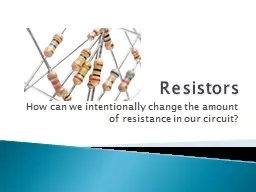
/
Resistors How can we intentionally change the amount of resistance in our circuit? Resistors How can we intentionally change the amount of resistance in our circuit?

Resistors How can we intentionally change the amount of resistance in our circuit? - PowerPoint Presentation

tatiana-dople
tatiana-dople . @tatiana-dople
Follow
380 views
Uploaded On 2018-11-25

Resistors How can we intentionally change the amount of resistance in our circuit? - PPT Presentation

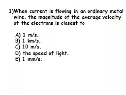
Resistance Voltage Current is a function of these two What if we want to control the current or alter the voltage Change the Resistance How do we do this Which of the three parts of Ohms triangle do we have the most control over ID: 733499

resistor voltage resistors lamp voltage resistor lamp resistors drop circuit amount band resistance component voltmeter gold light silver lamps

Share:

Link:

Embed:

Download Presentation from below link

Download Presentation The PPT/PDF document "Resistors How can we intentionally chang..." is the property of its rightful owner. Permission is granted to download and print the materials on this web site for personal, non-commercial use only, and to display it on your personal computer provided you do not modify the materials and that you retain all copyright notices contained in the materials. By downloading content from our website, you accept the terms of this agreement.


Presentation Transcript

Slide1

Resistors

How can we intentionally change the amount of resistance in our circuit?Slide2

Resistance

VoltageCurrent is a function of these two

What if we want to control the current or alter the voltage?

Change the Resistance!How do we do this?

Which of the three parts of Ohm’s triangle do we have the most control over?Slide3

Resistor – A component that resists the flow of electric current, or blocks/slows down the flow.

Resistors are very small, so we use color bands painted on them to signify how many ohms (units of resistance) they have.

Basic InformationSlide4

The color band at the end is decoded as a number.

The middle color band is also decoded as a number.

The third band tells you how many zeroes to write after the first two numbers.

Black

0

Brown 1

Red 2

Orange 3

Yellow 4

Green 5Blue 6Violet 7Gray 8White 9

How to Read the ColorsSlide5

Resistors

2 – 7 – (0 0 0 0 0)

2,700,000 ohms

The band to the left is red, so our first number is 2.

The second band from the left is violet so the next number is 7.

The third band is green so the amount of zeroes we add are 5.

This has 2,700,000 ohms of resistance.Slide6

Take a look at that picture again, and notice the gold band all the way on the right. We don’t have a value for gold or silver because they mean different things.

Gold means it is give or take 5% away from the value.Silver means it is give or take 10% away from the value.Slide7

The gold and silver bars are kind of like someone saying…

“Not quite sure if we are completely accurate, but it is within 5% (gold) or 10% (silver) of being right.

Gold is really good -> 5%

Silver is pretty good -> 10%Gold & SilverSlide8

Let’s Try Some Out

Violet-Green-Red

Red-Orange-Black

Green-Gray-Yellow

7500 ohms

23ohms

580,000 ohmsSlide9

What if we add the band at the end?

Brown-Gray-Orange - Gold18,000 (give or take 5

%)

18,000 x .95 = 17,10018,000 x 1.05 = 18,900

The range would be 17,100 – 18,900Slide10

Exploring ResistorsSlide11

Some resistors conduct electricity- - some don’t have enough to light the lamp

Actually all resistors conduct electricity, but some do not conduct enough to light a lamp.

All resistors in a series with lamps make the lamp glow dimmer.Slide12

Each different resistor in series with a lamp makes it glow with a different brightness.

Some resistors in parallel with lamps make the lamp dim a tiny bit; some resistors in parallel with lamps don’t affect the brightness of lamps.

Some resistors get warm when they are in parallel with a lamp. Slide13

The resistor makes the lamps dimmer. How can you explain this observation?Slide14

What do you think is happening inside the resistor to cause the lamp to burn with reduced intensity?Slide15

Resistor Investigation (option 1)

Find four resistors in your kit with colored bands.

Set up the circuit pictured to the right.

Put the resistors into the circuit one at a time and close the switch. Observe the intensity of the light from the bulb.List the resistors in order from brightest to dimmest light.Decode the color band and write the value of each resistor. Slide16

Resistors and lamp-brightness inquiry

(2)

Different resistors seem to affect lamps in different ways. Work with your partner to find out if this is true.

Design an efficient system for testing the different resistors.Draw a schematic to show your test circuit.

Conduct your investigation and gather data.

Organize your results in a way that is easy to understand. Slide17

Resistors and Lamp-Brightness Plan

(3)

Design an efficient system for testing the different resistors, one at a time, in series with a lamp.

Test each resistor and observe the lamp’s brightness.Put the resistors in order from brightest light to dimmest light.Record the resistor information in your journal, using the color-band names for the resistors.

Draw a schematic of your test circuit.Slide18

Lab

Pages 7 and 9 in your lab notebookSlide19

Measuring Voltage

3/9/2011Slide20

Electricity flows through circuits because it is pushed by a force is called

voltage.We measure voltage by setting the multimeter

to its voltmeter position touching the two meter probes to the two sides of a component.

The amount of voltage used by that component is reported as voltage drop.Slide21

How to use a Voltmeter

Turn the rotary switch three clicks counterclockwise to the

20-V Setting.

The meter is now a voltmeter. At this setting the voltmeter can measure voltage between 0 and 20 V.Set up a circuit and close the switch. Voltage is always measured with current flowing through the circuit.

Touch the two probes on the

two sides of

A

component

to measure its voltage drop. The red probe goes on the positive (+) side.

Read the voltage drop across the component on the display.Slide22

Voltage Drop

The difference in the amount of voltage on the two sides of a component is what the voltmeter measures. The voltmeter measures the amount of voltage “used” by a component.

The amount of voltage used by a component is its voltage drop.

We always refer to the voltmeter reading as a voltage drop.Slide23

Resistor/Voltage RelationshipSlide24

How do you explain the voltage drop across a lamp in a circuit?Slide25

Voltage drop is like energy that gets used up

Voltage drop is like the amount of push needed to get current through a component

.Slide26

The Greater the resistance in series with a lamp, the dimmer the lamp glows.Slide27

***** Important *****

Add a resistor to your investigation.

Use black/black/black - - or 0-

Ω resistanceHow could you make a resistor with 0-Ω of resistance? (The copper wire)Slide28

Class Data

Use the 0-Ω resistor data - -

Lets compare our data as a class

Cross off the highest and lowest values. Average all the valuesSlide29

Is there a pattern in the amount of voltage drop across the resistor?Slide30

Is there a pattern in the amount of voltage drop across the resistor?

The greater the resistance the greater the voltage drop across the resistor.Slide31

Is there a pattern in the amount of voltage drop across the lamp?Slide32

Is there a pattern in the amount of voltage drop across the lamp?

The greater the resistance, the less the voltage drop across the lampSlide33

How do these voltages-drop patterns relate to the size of the resistor in the circuit with the lamp?Slide34

How do these voltages-drop patterns relate to the size of the resistor in the circuit with the lamp?

As the resistance increases, the voltage across the resistor increases and the voltage across the lamp decreases.Slide35

Add up the lamp and resistor voltages for each resistor. Is there a pattern?Slide36

Add up the lamp and resistor voltages for each resistor. Is there a pattern?

The sum of the voltage drops in the circuit equals the available voltage across the terminals of the battery. Slide37

Lab

Page 12 in your lab notebook