/
Slides created by:  Professor Ian G. Harris Slides created by:  Professor Ian G. Harris

Slides created by: Professor Ian G. Harris - PowerPoint Presentation

tatiana-dople
tatiana-dople . @tatiana-dople
Follow
389 views
Uploaded On 2018-02-27

Slides created by: Professor Ian G. Harris - PPT Presentation

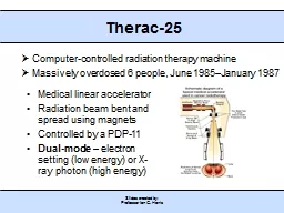
Therac25 Computercontrolled radiation therapy machine Massively overdosed 6 people June 1985January 1987 Medical linear accelerator Radiation beam bent and spread using magnets Controlled by a PDP11 ID: 637455

created device professor slides device created slides professor ian harris write driver data file read struct mem system mode user hardware position

Share:

Link:

Embed:

Download Presentation from below link

Download Presentation The PPT/PDF document "Slides created by: Professor Ian G. Har..." is the property of its rightful owner. Permission is granted to download and print the materials on this web site for personal, non-commercial use only, and to display it on your personal computer provided you do not modify the materials and that you retain all copyright notices contained in the materials. By downloading content from our website, you accept the terms of this agreement.


Presentation Transcript

Slide1

Slides created by: Professor Ian G. Harris

Therac-25

Computer-controlled radiation therapy machineMassively overdosed 6 people, June 1985–January 1987

Medical linear accelerator

Radiation beam bent and spread using magnets

Controlled by a PDP-11

Dual-mode

– electron setting (low energy) or X-ray photon (high energy) Slide2

Slides created by: Professor Ian G. Harris

History of the Device

Therac-6Photon mode only

Manual device, PDP-11 for convenience

Hardware safety features

Therac-20

Dual mode device

Manual device, PDP-11 for convenience

Hardware safety

features

Therac-25

Dual mode device

Automatic device PDP-11 required

Some hardware

safety

features replaced by softwareSlide3

Slides created by: Professor Ian G. Harris

Turntable

Rotates equipment into the beam path3 modes, 3 sets of equipment

Electron mode – scan magnets to spread beamX-ray photon mode – flattener needed to focus and weaken beam

Very high energy beam

Field light position – mirror needed to pass light

Mirror

Turntable in the wrong position =

D

eathSlide4

Slides created by: Professor Ian G. Harris

Basic Operation

Operator enters desired parametersEach parameter is verified by sensors

After all parameters are verified, operator can type ‘p’ for ‘proceed’

Treatment Pause shutdown

Small parameter variation

Wait 5

secs

, press ‘p’

Treatment Suspend shutdown

Major problem

Must reset systemSlide5

Slides created by: Professor Ian G. Harris

Therac-25 Software

Borrowed code from Therac-20

Assumed that the code was goodIgnored the fact that hardware safety had been removed

Written in PDP 11 assembly code

Real-time OS developed for this device

Preemptive, priority scheduling algorithm

0.1 second time quantumSlide6

Slides created by: Professor Ian G. Harris

Software Tasks

Critical TasksTreatment Monitor

– manages all stages of the setup and treatment processServo

Task

– controls gun emission, dose rate, beam steering, and machine motions

Housekeeper Task

– performs checks of system status, limits, displays messages to CRT

Non-Critical Tasks

Keyboard processor

Screen processor

Hand task

– set turntable to proper position for selected mode/powerSlide7

Slides created by: Professor Ian G. Harris

Data Entry Process

Treat task accepts data in the Datent

stateKeyboard handler writes data to the MEOS

structure

Hand task uses low byte of MEOS to

rotate turntable

Keyboard handler assumes that:

data entry is complete when the cursor is at the bottom of the page

Does not consider parameter correctionsSlide8

Slides created by: Professor Ian G. Harris

Data Entry Complete

When data entry is complete, Datent does the following

Calls MAGNET subroutine to adjust bending magnets

Move to Set Up Test state (apply radiation)

MAGNET subroutine takes time (8sec), calls

Ptime

for each magnet

Ptime

exits if MEOS is changed, but

only on the first call to

Ptime

If MEOS changes during calls to

Ptime

(other than the first), the change is not registered by Hand

Possible Error

Operator sets

field light mode

by mistake

Turntable rotates to mirror

Operator

quickly changes mode to

photon mode

X-ray photons are emitted with no attenuationSlide9

Slides created by: Professor Ian G. Harris

Software Problems

Bytes of MEOS can be non-correlated

Offset parameters byte can be updated while mode/energy byte changes are ignoredAccess to MEOS should be mutually exclusive

No read access while data entry is not complete

Proper detection of Data Entry Complete

Solution

“the key for moving the back through the prescription sequence must not be used for editing or any other purpose.”Slide10

Slides created by: Professor Ian G. Harris

Second Bug

Occurred during the Set Up Test phase, after

DatentEach pass through Set Up Test increments the turntable position check variable

Class3

If Class3 is non-zero then the turntable position must be checked to match the parameters

Set Up Test is executed hundreds of times

Rescheduled waiting for other events

Class3 is 1 byte long

Every 256

th

pass through Set Up Test, checking is not performed

If the operator presses “set” on pass 256, turntable position can be in field light positionSlide11

Slides created by: Professor Ian G. Harris

Hardware Abstraction

A processor may use many types of I/O devices

Each device has a different interface

Look at the datasheets

Applications cannot handle variations in hardware

There are far too

many

Operating systems

abstract hardware details

from user processes

Disk vs. USB flash – no differenceSlide12

Slides created by: Professor Ian G. Harris

Device Drivers

A uniform interface (mostly) for the interaction between SW and HW devices

User Application

Library Function

System Call

Device Driver

HW

User

Space

Kernel

Space

“Hello, world.”

printf

vfprintf

HDMI or UART driver

HDMI or UART portSlide13

Slides created by: Professor Ian G. Harris

Functions of Device Drivers

Initialize the deviceAccept read/write requests from the layer above

Check validity of input parameters

Add device-specific detail to requests

Disk write – track, sector, cylinder number

Check if device is in use

Control the device

Conform to device input protocol (SATA, I2C, …)

Respond to device

i.e. accept incoming network messageSlide14

Slides created by: Professor Ian G. Harris

Device Driver Implementation

Interface to system calls is defined as a standard set of functions

Driver code must convert system requests into I/O signaling in the protocol of the device

Must respond to

interrupts

from the device

Driver may include

interrupt service routines

Device Driver

System Call

HW Device

v

oid

vfprintf

(…) {

open

(device

);

write

(

device,data

);

VGA Controller

IC

I/O protocol

InterruptsSlide15

Slides created by: Professor Ian G. Harris

Device Driver Protocol

Each interface function in the driver should write appropriate data into the device registers

Most devices have registers to accept commandsTypically write to them using standard bus protocol (I2C, etc.)

After writing a command,

verify that command is accepted

Check error conditions (ACK or NACK, etc.)

Synchronize

with the device I/O

Block or not, wait for interrupt or not

Several options on this

Structure for the behavior of a device driverSlide16

Slides created by: Professor Ian G. Harris

File System Interface

All devices look like files on a linux

systemSpecial files are created, usually in the

/

dev

directory

Device interaction is the same (mostly) as file interaction

User programs

Virtual

File System Switch

Hardware

f

d

=

open

(“/

dev

/

abc

”)

read

(

fd

)

write

(

fd,dat

)

close

(

fd

)

abc_open

()

abc_read

()

abc_write

()

abc_close

()

System calls

Device driver routinesSlide17

Slides created by: Professor Ian G. Harris

Driver Routine Execution

Execute as part of the operating system

Need highest access to interact with HWCan be compiled into the kernel

Common on embedded systems

Drivers are fixed

Can be

loaded dynamically

Loadable Kernel Modules (LKM) in

linux

Bugs in drivers can be damaging

Same access as OS

Security vulnerabilities

are an issueSlide18

Slides created by: Professor Ian G. Harris

Types of Devices

Three types depending on how data is transferredCharacter Device

Can read and write individual characters efficiently to this device

Block Device

M

ore efficient to read/write blocks of data (i.e. disk drives)

I/O buffering is commonly used

Network Device

Device needs to be services periodically

Interrupts are neededSlide19

Slides created by: Professor Ian G. Harris

Major and Minor Numbers

Each device is assigned a major number which indicates the device type and its driver

Minor number is the specific device within the major number

Name

Create/Owner

Permissions

Major

Minor

/

dev

/usbmon0

root, root

crw

-------

252

0

/

dev

/usbmon1

root, root

crw

-------

252

1Slide20

Slides created by: Professor Ian G. Harris

Device Driver Interface

Each device must implement an interface according to its type

Character drivers implement the file_operations

interface

struct

file_operations

{

ssize_t

(*

read

) (

struct

file *, char *,

size_t

,

loff_t

*);

ssize_t

(*

write

) (

struct

file *,

const

char *,

size_t

,

loff_t

*);

int

(*

ioctl

) (

struct

inode

*,

struct

file *, unsigned

int

, unsigned long);

int

(*

open

) (

struct

inode

*,

struct

file *);

int

(*

release

) (

struct

inode

*,

struct

file *);

};

o

pen, release, read, write

are the basicsSlide21

Slides created by: Professor Ian G. Harris

Driver Routine Example

Need a driver for an SRAM chip connected via I2CWe did this before

Philips PCF8570, 256 locations, 8-bit

Decide how to map

device access

to

file access operations

Device is

random access

but files are

sequential access

Solution:

Make device sequential accessMaintain

readPtr and writePtr for next read/write access address

Read operation reads from

readPtr

++

Write operation writes to

writePtr

++Slide22

Slides created by: Professor Ian G. Harris

o

pen and release

Note: This is a simplified version

D

river-specific data structure in the

inode

,

mem_dev

i

nt

mem_open

(

struct

inode

*

inode

,

struct

file *file){

mem_dev

->

readPtr

= 0;

mem_dev

->

writePtr

= 0;

return 0;

}

i

nt

mem_release

(

struct

inode

*

inode

,

struct

file *

fd

){

return 0;

}Slide23

Slides created by: Professor Ian G. Harris

w

rite considerations

Write takes 4 argumentss

truct

file

*

fp

: file pointer (not needed)

c

har

*

buf

: buffer to write to device

size_t

count

: number of bytes to write to device

l

off_t

*

ppos

: Position in device to write to

Should be

mem_dev

->

writePtr

Copying data requires special functions

User space and kernel space may have different memory mappings

May not trust pointers provided by user app

copy_to_user

(),

copy_from_user

()Slide24

Slides created by: Professor Ian G. Harris

w

rite implementation

int

mem_write

(

struct

file *

fp

, char *buff,

size_t

cnt

,

loft_t

*

ppos

){

char data;

for (

int

i

=0;

i

<

cnt

;

i

++) {

copy_from_user

(&data,

buff+cnt

, 1);

WriteMTSR

(MEM_I2C_ADDR, (*

ppos

)++, data);

}

return 0;

}

WriteMTSR

writes a char to an I2C slave at the given address

MEM_I2C_ADDR

is the I2C address of the memory

Must update

*

pposSlide25

Slides created by: Professor Ian G. Harris

init

Function

init

is called when the driver is loaded

Or during boot for a static driver

Responsibilities:

Associating a device major number with the driver

Allocating memory for the per-device structure

Connecting the entry points (open(), read(), etc.) with the driver

Initializing hardware

Check if it existsSlide26

Slides created by: Professor Ian G. Harris

r

egister_chrdev Function

Registers the driver with the virtual file system switch (VFS)

struct

file_operations

mem_fops

= {

NULL, /*

lseek

() */

mem_read

, /* read() */

mem_write

, /* write() */

};

long

mem_init

(long

kmem_start

) {

printk

("Sample Device Driver Initialization\n");

if (

register_chrdev

(22,

mem

", &

mem_fops

))

printk

("error--cannot

register!\

n");

TurnOnI2C();

return 0

;

} Slide27

Modified version of slide by Paul Krzyzanowski

Buffered I/O

Kernel copies the write data to a block of memory (buffer):

Allow the process to write bytes to the buffer and continue processingBuffer does not need to be written to the disk … yet

Read

operation:

When

the device is ready, the kernel places the data in the buffer

Why

is buffering important?

Deals

with device

burstiness

Rate mismatch between host and deviceCaching

(for block devices)Alignment (for block devices)Slide28

Modified version of slide by Paul Krzyzanowski

Buffer Cache

Pool of kernel memory to hold frequently used blocks from block devicesMinimizes the number of I/O requests that require device I/O

Allows applications to read/write from/to the device as a stream of bytes or arbitrary-sized blocks

User I/O Requests

Buffer

Cache

Device Block I/O Requests

f

ast

slow