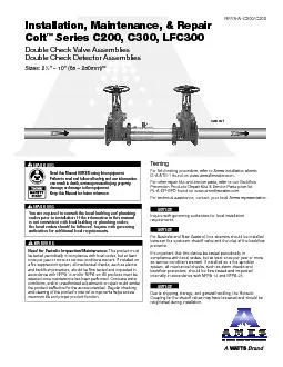
/
6. Closure Sleeve Test Cock with O-ring7. Closure Sleeve5. E-clip and 6. Closure Sleeve Test Cock with O-ring7. Closure Sleeve5. E-clip and

6. Closure Sleeve Test Cock with O-ring7. Closure Sleeve5. E-clip and - PDF document

tatyana-admore
tatyana-admore . @tatyana-admore
Follow
409 views
Uploaded On 2016-02-26

6. Closure Sleeve Test Cock with O-ring7. Closure Sleeve5. E-clip and - PPT Presentation

8 Sleeve Oring 3 Check Module Oring1 First Check Module PartsRPISAC200C300 1322EDP 7018382 ID: 232036

Sleeve O-ring

Share:

Link:

Embed:

Download Presentation from below link

Download Pdf The PPT/PDF document "6. Closure Sleeve Test Cock with O-ring7..." is the property of its rightful owner. Permission is granted to download and print the materials on this web site for personal, non-commercial use only, and to display it on your personal computer provided you do not modify the materials and that you retain all copyright notices contained in the materials. By downloading content from our website, you accept the terms of this agreement.


Presentation Transcript

Double Check Valve Assemblies WARNING Failure to read and follow all safety and use information can result in death, serious personal injury, property damage, or damage to the equipment. You are required to consult the local building and plumbing the local codes should be followed. Inquire with governing authorities for additional local requirements. WARNING ! This product must be tested periodically in compliance with local codes, but at least once per year or more as service conditions warrant. If installed on a re suppression system, all mechanical checks, such as alarms and backow preventers, should be ow tested and inspected in accordance with NFPA 13 and/or NFPA 25. All products must be retested once maintenance has been performed. Corrosive water conditions, and/or unauthorized adjustments or repair could render the product ineffective for the service intended. Regular checking and cleaning of the product’s internal components helps assure WARNING ! NOTICE Inquire with governing authorities for local installation requirements NOTICE For Australia and New Zealand, line strainers should be installed between the upstream shutoff valve and the inlet of the backflow It’s important that this device be tested periodically in compliance with local codes, but at least once per year or more Due to shipping, storage, and general handling, the Victaulic Coupling for the shutoff valves may have loosened and should be TestingFor field testing procedure, refer to Ames installation sheets IS-A-ATG-1 found on www.amesfirewater.com.For other repair kits and service parts, www.amesfirewater.comFor technical assistance, contact your local Ames representative. 2Basic Installation InstructionsGuidelinesMost field problems occur because dirt and debris present in the system at the time of installation becomes trapped in the check valves. The system should be The Series C200 and C300 may be installed in either horizontal or vertical position as long as the backflow assembly is installed in accordance with the direction of the NOTICEAssembly body should not be painted. Horizontal InstallationVertical Installation WARNING shutoff valves. After shutoff valves are closed, open test cock #2, #3 & #4 to relieve pressure within the backflow assembly.After #3 test cock has been opened to relieve pressure, remove #3 test cock from housing. (Figure A)Insert a #3 screwdriver through the hole on the top of the cover sleeve and using both hands rotate the cover sleeve approximately -turn clockwise and -turn counter-clockwise to break the sleeve O-ring seals. Using the screwdriver, slowly slide the cover sleeve to the downstream side of the housing. (Figure B)Remove the stainless steel check retainer from the housing. (Figure B)4. Remove the #1 check module (Figure C) by inserting two flat blade screwdrivers into the slots on either side of the check module and gently pry the check module toward theopen zone. 6. To clean or inspect either check module, insert a #3 screwdriver through the downstream side of the check module as shown in Figure D & E. When the screwdriver is in place, remove the “E”-clip (Figure F) and pin connecting the structural members Thoroughly clean the seating area. The sealing disc may be removed, if necessary, by removing the screws connecting the keeper plate to the clapper. The sealing disc may be reversed and reinstalled if the elastomer is cut or damaged.Wash check module and O-ring and inspect for any damage. If damaged, reinstall new parts.After thorough cleaning, lubricate O-ring w/FDA approved lubricant, replace pin and “E”-clip in structural members, remove screw driver and reinstall check modules and assemble housing in reverse order of these instructions. Figure DFigure EFigure F Figure AFigure BFigure C Maintenance Instructions 21/2" – 6" (65 – 150mm) 3Ball Type Test ValvesACB NeedleValve High Hose(Yellow) Low Hose(White or Red) Vent Hose (Blue) Test CockTest CockTest CockTest Cock No. 1No. 2No.3No.4 Step 1:Move the high side hose to test cock #4, low side to test cock #3 and open both test cock #3 and test cock #4. Step 2: turn, Step 3:If the differential gauge rises above 0, there is excessive leakage at shutoff #2 and it must be replaced to test the WARNING Prior to servicing any Ames valve, it is tem by closing both the inlet and outlet shutoff valves. After shutoff valves are closed, open test cock #2, #3 & #4 to relieve pressure within the backflow assembly.5.Insert the Phillips screwdriver through the arbors and service hole of the linkage making sure that the tip of the screwdriver extends 6.8.To remove spring mechanism, grasp the screwdriver at the center WARNING !While the spring mechanism is removed for check servicing; never pull the screwdriver out or off the support notches on the arbors. Maintenance Instructions 8" – 10" (200 – 250mm)Testing — Double Check Valve Assemblies Figure AFigure BService Hole 6. Closure Sleeve Test Cock with O-ring7. Closure Sleeve5. E-clip and Clevis Pin4. Elastomer Shutoff Disc2. Second Check Module 8. Sleeve O-ring 3. Check Module O-ring1. First Check Module Parts For repair kits and parts, refer to our Backflow Prevention Products Repair Kits & Service Parts price list PL-A-RP-BPD found on www.amesfirewater.com. sage for a period of one year from the date COMPANY MAKES NO OTHER UT NOT LIMITED TO THE l, or any other circumstances over which the Company has no control. ation of incidental or consequential damages. Therefore the above limitations may not apply to you. This Limited Warranty gives you specific legal rights, and you may have other rights that vary from State to State. You should consult applicable state laws to RANTIES WARNING: This product contains chemicals known to the State of California to cause cancer and birth defects For more information: Watts.com/prop65