/
By Anthony Pietrangelo, P.E. MDOT Geotechnical Construction Support En By Anthony Pietrangelo, P.E. MDOT Geotechnical Construction Support En

By Anthony Pietrangelo, P.E. MDOT Geotechnical Construction Support En - PDF document

tatyana-admore
tatyana-admore . @tatyana-admore
Follow
465 views
Uploaded On 2016-03-07

By Anthony Pietrangelo, P.E. MDOT Geotechnical Construction Support En - PPT Presentation

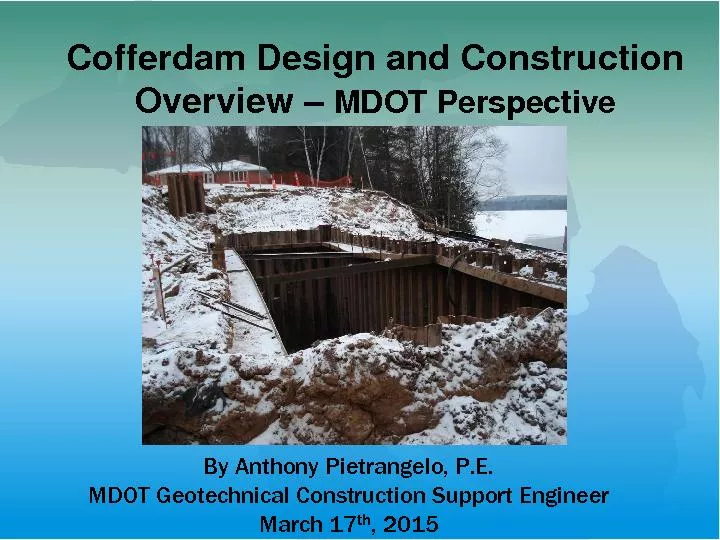
March 17 th 2015 Cofferdam Design and Construction Overview MDOT Perspective Presentation OverviewCofferdam OverviewMDOT SpecificationsContractor Submittal of Calculations and DrawingsBasics of Desi ID: 245490

March 17 th 2015 Cofferdam Design and

Share:

Link:

Embed:

Download Presentation from below link

Download Pdf The PPT/PDF document "By Anthony Pietrangelo, P.E. MDOT Geotec..." is the property of its rightful owner. Permission is granted to download and print the materials on this web site for personal, non-commercial use only, and to display it on your personal computer provided you do not modify the materials and that you retain all copyright notices contained in the materials. By downloading content from our website, you accept the terms of this agreement.


Presentation Transcript

By Anthony Pietrangelo, P.E. MDOT Geotechnical Construction Support Engineer March 17 th , 2015 Cofferdam Design and Construction Overview MDOT Perspective Presentation OverviewCofferdam OverviewMDOT SpecificationsContractor Submittal of Calculations and DrawingsBasics of DesignGeotechnicalStructuralConstruction ProceduresSoil Types and Effects on Construction and DesignCommon Issues in Design and ConstructionGuidance Documents and FormsSafety GeneralCofferdams. Construct partial or total enclosure cofferdams that permit construction of the substructure, above the seal or subfooting, in the dry without damage to the work. 704.03.CPay Item Cofferdams Includes:DesigningFurnishingInstalling MaintainingRemoving or cut offIncludes steel sheet piling, bracing, tieback, tieback testing, walers and other related materials. General MDOT SpecificationsMDOT 2012 Standard Specifications for Construction section 704SSC Subsection 104.02 Working DrawingsMDOT Bridge Design ManualAASHTO Standard Specifications for Highway Bridges 17EditionContract PlansProject specific Special Provisions included in Contract MDOT 2012 Standard Specifications for ConstructionSpecification RequirementsSubsection 104.02 Plans and Working DrawingsRequirement for contractor to submit working drawings and calculations for cofferdams. Where the combined depth of retained water and soil is lessthan 6 feet the contractor is required to submit working drawings for cofferdams prepared by an engineer competent in geotechnical and structural engineering.Where the combined depth of retained water and soil is greaterthan 6 feet the contractor is required to submit working drawings for cofferdams prepared by a professional engineer, licensed in the State of Michigan competent in geotechnical and structural engineering. The working drawings and calculations must be sealed by the licensed engineer. MDOT 2012 Standard Specifications for ConstructionSpecification RequirementsSubsection 704 Steel Sheet Piling and CofferdamsProvide new or used continuous interlocking steel sheet piling including connections in corner pieces. Used sheeting must be in good conditions.Provide minimum nominal section modulus of at least 18.1 cubic inches per foot of wall when installed next to traffic or supporting traffic loads.Both cold and hot rolled sheeting is permitted.A copy of the cofferdam design and working drawings shall be provided and maintained at the job site as required by MIOSHA Construction Safety StandardVibratory hammers are permitted see plan notes for exclusionsDo not pull up or redrive sheeting to match cut off elevation. MDOT 2012 Standard Specifications for ConstructionDesign in accordance with the AASHTO Standard Specifications for Highway Bridges, 17Edition.Sheet piling section modulus and embedment depthDesign criteria for bracing and bracing sections, connection and tieback details, and deadman sections. Assumptions and references for the design calculationsAny temporary loads for construction equipment, construction materials, traffic loading and any unbalanced hydrostatic pressure loadingProfile and Plan Views with cross sectionsAll located in Subsection 704.03.A Contract PlansMay Include:Minimum section modulusMay call out specific typeDepth of sheeting may need to be reviewed if different section is being proposed.Minimum Embedment DepthsProhibit use of Vibratory HammersOnly hot rolled sheeting is permitted.Overall cofferdam dimensions. Cut off elevationsTremie thickness Special ProvisionsCommon items included in Special ProvisionsDeflection Criteria, 2.0 inches maximum Design based on Geotechnical Engineering Software including the following programsSPW 911 by PileBuck International Inc.SupportIT by GT Soft Ltd.CivilTech Software Shoring Suite Other software will be reviewed by the Department and requires approval prior to use.Hand calculations for structural designs and details are acceptable. Special Provisions ContinuedInclude a minimum Live load surcharge of 360 psf.Construction equipment loaded must be accounted for and may increase the live load surcharge. i.e. Crain Loads applied directly behind sheeting.Sheeting adjacent to existing spread footings shall be designed using a uniform surcharge equal to the applied footing pressure. Bottom stability (piping and heave) and overall (global) stability evaluated for all stages of construction. Minimum factors of safety are included in SP. Design/Submittals:Contractor’s ResponsibilitySubmit proposed design to Construction Engineer 10 working days before starting work. (Standard Specs.)Special Provisions may require longer review cycle times.Multiple review cycles may be needed. Show sheet piling, section modulus, embedment depth, water level and bracing details.Excavation profile.Make sure cofferdam design are constructible.Work begins after Engineer’s acceptance. Design/Submittals:Engineer’s ResponsibilityEngineer shall check the following:Section modulus of sheet pilingMethod of excavation, “dry” vs. “wet”Hydrostatic forcesConstruction staging and sequence.Supporting Calculations for ever step in the excavation process.Clearly define each construction sequenceProvide room for waler installation Excavation ProfileToe Embedment of the sheet pilingBracingIf requiredStructural CalculationsConnection DetailsTwo or more rows of Bracing require Apparent Earth Pressure Model used to calculate earth loads. Design/Submittals:Engineer’s ResponsibilityBattered Pile vs Sheet Piling ConflictIf cofferdam is widened, Tremie design must be revisited by contractors Design Engineer.Tremie is a designed element from Bridge Design EngineerConsult MDOT Bridge Design Manual on Bending Stress analysisDriveabilty AnalysisSoil ProfileSands vs ClaysCobbles / BouldersVibratory hammer may not be as critical as Impact hammerSheeting must be able to with stand impact driving stresses. Other External LoadsSurcharge LoadsSoil surcharges (i.e. sloping backfill) You never know what might end up on top of the cofferdam Construction Sequencing Staging Details of CofferdamsLayout of cofferdams shall match maintaining traffic staging details, and structure removal limitsMinimum lane width, barrier, and bar splices shall be accounted for in layout.Coordinate with culvert manufacture to find out all culvert section dimensions.Stream diversion plan shall be included if required. Staging Details Design ProgramSPW911 Sheet PilesHot Rolled vs. Cold RolledHartman Reduction FactorStraight, ArchWeb, DeepWeb, & ZSections Cold RolledProduced from a coil by cold rolling the coil into a sheet pile shape.“Loose” interlock compared to hot rolled.Uniform thickness.Thickness limited to ½” based on coil thickness.Residual stresses in bends due to rolling process. Cold Rolled Hot Rolled Section35 Section ExampleBall and Socket InterlockBetter interlockMore points of contact.Joints are less likely to leak than cold rolled Easier to install Less FrictionAlignmentGenerally specified in permanent applications Hot Rolled vs. Cold RolledEffective vs. Nominal Section ModulusHot Rolled and Cold Rolled Nominal Section Modulus.Contractor’s Engineer should check availability of Sheet Piling before specifying.Hartman Reduction FactorIllinois DOT83% Lower Bending Failure Stress Construction ProceduresBracing MethodsSheeting Installation MethodsInspector to Verify Cofferdam Construction Matches Cofferdam Submittal Excavations MethodsTremie Seal/Pour BracingStrutsWalersTie BacksBracing Rings Internal Bracing Use of Walers and Struts to internally transmit loadTremie may also used as a brace point once minimum strengths are achieved. Strut and Wale Bracing Bracing Rings WalingWaling transmits forces from the sheet piling internally from side to side or into the anchor assembly. The wailing assembly may composed of struts (HP or W sections), channels, tie rods and connection bolts. Walers could also be used as a driving template to keep sheeting lines straight. Walers should be in contact with the steel sheet piling.Gaps will need to be filled in with a structural detail Structural and Connection DetailsWeld details and call outsProperly size walers and strutsCorrect end support conditionsFixed Fixed Pinned PinnedFree endContinuous WalersSplice detailNegative MomentsStructural Detail for when waler is not in contact with sheet pileMost common failure mechanism is connection details/failures This is what is being built! This is what is being built! Installation Methods: Impact Hammer vs. Vibratory Hammer Installation Methods/Soil Types:Driving Steel Sheet Piling, Vibratory vs. Impact HammerDesigners typically add notes indicating if vibratory hammers are not permitted.Method used based on soil type and nearby structures.Contractors prefer Vibratory Hammer for sandy soils.Cohesive soil responds better to a Impact Hammer.Driveability analysis may need to be performed for Impact Driven sheeting. Size sheeting accordingly Excavation/Soil Types Wet vs. Dry ExcavationCohesive vs. GranularExcavation Done Before Driving PilesEquipment UsedClam ShellCraneExcavatorSoundings Tremie SealRequired ThicknessBased on uplift resistance to sheet piling/piles and weight of concrete mass to resist hydrostatic forces.Allowable skin friction can not be greater then pull out resistance of sheet piling and piles.MDOT Bridge Design Manual also list allowable bond stresses.Bending Stress Calculation of unreinforced concreteGenerally controls if foundation piles are used. Required Strength Before Dewatering(706.03.H.3) Grade T ConcreteBefore Pouring Tremie, Verify All Soil Has Been Cleaned Out of Sheet Piling.Pockets of sheet piling should be checked Tremie Tube Shall be Kept Embedded into Tremie Concrete. Tremie Pour in the “Wet” Removal of sediments after tremie pour. Guidance Documents MDOT Form 1990 MDOT Form 1990Cofferdam Installation, Piling Placement, and Tremie Pour Inspector’s Checklist.Form is available on the MDOT forms website.Developed to prevent reoccurring geoconstruction issues.Highlights sections already included in the 2012 Spec Book SafetyLimited AccessWet excavations/conditionsDeep ExcavationsAdequate Walkways, Rails, and LaddersFlotation DevicesMIOSHAPart 9. Excavation, Trenching, and ShoringExcavati�ons 5 ftMIOSHA requires sealed cofferdam design be maintained on site How safe is this? Cofferdams should be designed and detailed so contractor and MDOT inspector can easily construct cofferdam and all required components.All construction stages clearly definedStructural members and connection details should be clearly detailed and understood.Cofferdams are contractor’s temporary works and can be revised as field conditions dictate.However, changes must be reviewed and approved by design engineer, working drawings revised and resealed, reviewed and approved by MDOT. Closing Thoughts Summary of PresentationMDOT SpecificationsBasics of DesignConstruction ProceduresSoil Types and Effects on Construction and DesignSafetyQuestions?