/
INTERNATIONAL CONFERENCE ON RENEWABLE ENERGY AND POWER QUALITY (ICREPQ INTERNATIONAL CONFERENCE ON RENEWABLE ENERGY AND POWER QUALITY (ICREPQ

INTERNATIONAL CONFERENCE ON RENEWABLE ENERGY AND POWER QUALITY (ICREPQ - PDF document

tawny-fly
tawny-fly . @tawny-fly
Follow
398 views
Uploaded On 2017-11-26

INTERNATIONAL CONFERENCE ON RENEWABLE ENERGY AND POWER QUALITY (ICREPQ - PPT Presentation

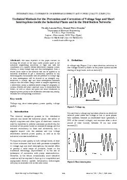
Figure 1 Voltage sag It is said that a voltage sag has taken place in an electrical network point when the voltage in one or more phases httpsdoiorg1024084repqj01442 REPQJ Vol 1 No1 A ID: 610124

Figure Voltage sag.

Share:

Link:

Embed:

Download Presentation from below link

Download Pdf The PPT/PDF document "INTERNATIONAL CONFERENCE ON RENEWABLE EN..." is the property of its rightful owner. Permission is granted to download and print the materials on this web site for personal, non-commercial use only, and to display it on your personal computer provided you do not modify the materials and that you retain all copyright notices contained in the materials. By downloading content from our website, you accept the terms of this agreement.


Presentation Transcript

INTERNATIONAL CONFERENCE ON RENEWABLE ENERGY AND POWER QUALITY (ICREPQ’03) Technical Methods for the Prevention and Correction of Voltage Sags and Short Interruptions inside the Industrial Plants and in the Distribution Networks Nicolás Louzán Pérez, Manuel Pérez DonsiónDepartment of Electrical Engineering E.T.S.I.I., Vigo University Lagoas – Marcosende, 36202 Vigo (Spain) Phone:+34 986 812685, fax:+34 986 812601 e-mail:donsion@uvigo.es Figure 1: Voltage sag. It is said that a voltage sag has taken place in an electrical network point when the voltage in one or more phases https://doi.org/10.24084/repqj01.442 RE&PQJ, Vol. 1, No.1, April 2003 Figure 2: Short interruption. 628 The maximum limit of this period is probably the most controversial issue about the voltage sag definition: some authors consider that a voltage sag exists when its duration reaches 1 min[3], or even 3 min. The expected number of events during one year can oscillate between ten and a thousand[3]. Short interruptions (Figure 2) cause a complete loss of voltage and are a common result of the actions taken by utilities to clear transient faults on their systems[1]; that is, when the voltage in the supply points does not go beyond the 10% of the normal voltage. The expected number of events during one year can oscillate between ten and some hundreds[3]. Sources of Sags and Short Interruptions Power systems have non-zero impedances, so every increase in current causes a corresponding reduction in voltage. Usually, these reductions are small enough that the voltage remains within normal tolerances. But when there is a large increase in current, or when the system impedance is high, the voltage can drop significantly. So conceptually, there are two sources of voltage sags: Large increases in current. Increases in system impedance. As a practical matter, most voltage sags are caused by increases in current. It is possible to think of the power system as a tree, with the customer sensitive load connected to one of the twigs. Any voltage sag on the trunk of the tree, or on a branch leading out to the customer twig, will cause a voltage sag at its load. But a short-circuit out on a distant branch can cause the trunk voltage to diminish, so even faults in a distant part of the tree can cause a sag at customer load[4]. The cause of most voltage sags is a short-circuit fault occurring either within the industrial facility under consideration or on the utility system. The magnitude of the voltage sag is mainly determined by the impedance between the faulted bus and the load, and by the method of connection of the transformer windings[6]. The voltage sag lasts only as long as it takes the protective device to clear the overcurrent condition (typically up to 10 cycles)[5], therefore the duration of the sag is determined by the fault-clearing time of that protection system adopted. Moreover, if automatic reclosure is used by the utility, the voltage sag condition can occur repeatedly in the case of a permanent fault. Finally, depending on its magnitude and duration, the sag can cause an equipment trip, thus becoming a power quality problem[6]. The most common causes of facility-sourced voltage sags Starting a large load, such as a motor or resistive heater. Loose or defective wiring, such as insufficiently tightened box screws on power conductors. Faults or short circuits elsewhere in the facility (trees, animals, adverse weather such as wind or lightning). Voltage sags can also originate on the utility's electric power system. The most common types of utility-sourced voltage sags are: Faults on distant circuits, which cause a corresponding reduction in voltage on your circuit. Voltage regulator failures (far less common). Fundamental Principles of Protection Several things can be done by the utility, customer and equipment manufacturer to reduce the number and severity of voltage sags and to reduce the sensitivity of the equipment to voltage sags. Figure 3 illustrates four solutions alternative. As this chart indicates, it is generally less costly to tackle the problem at its lowest level, close to the load[1], because solutions such as enhanced equipment specifications cost a few dollars since sensitive parts have very low current ratings[5]. As solutions at higher levels of available power are entertained, the solutions often become more expensive[1]. OTHER LOADSMOTORSCONTROLS 2 3 SourceGroup ofMachines 4. Utility Soluitions3. OverallProtectionInside Plant2. ControlsProtections1. EquipmentSpecificationsCustomer Solutions Increasing costSensitive Process Machine Figure 3: Solutions at different levels and involved cost. Methods for Mitigation Voltage Sag Impact On Industrial Installations Tap Changing Transformers Electronic tap changing is achieved via the use of back-to-back thyristors (SCR) with a tap changing transformer. Has a reasonable response time (1 cycle) and is popular for medium power applications� (3kVA). However, high control resolution requires large number of SCRs (60 SCRs for +/-3% regulation with +10/-20% input range); the control for fast response becomes fairly complex. Another drawback of this scheme is its susceptibility to 629 high transient current with motor loads upon tap changing and its poor transient voltage rejection[7]. Saturable Reactor Regulators This scheme controls the output voltage by varying the impedance of a saturable reactor: it is simple and has a good line transient rejection. The drawbacks of this technique include slow response (10 cycles), high output impedance which gives high distortion with non-linear loads sensitive to load power factor, will not handle surge currents such as motor starting and will not suppress transients generated inside plant[7]. Motorized Variacs Motor driven variacs are operated to maintain output voltage regulation. This scheme can handle heavy surge currents frequently used in industrial setting due to high surge capability. On the other hand, it has a slow response (30 V/s) and is not suitable for sensitive equipment. In addition, it has substantial maintenance requirements and poor transient suppression. Its slow response limits its effectiveness[7]. Phase Controlled Regulators This technique uses phase controlled thyristors with LC filter to control output voltage[8]. It has a slow response, high distortion especially with non-linear loads, over sized filters, very poor input line harmonics and will not handle surge currents such as motor starting. This scheme has good line transient suppression but will not suppress transients generated inside plant[7]. Electronic Voltage Regulators They are a new class of automatic voltage regulators based on high frequency switching inverter technology. It can provide fast response (1-2 ms), sinusoidal voltages, and compact design. This category of voltage regulators potentially offers the highest performance solution. However, designing appropriate overload capability can make the overall cost unacceptably high. In order to realize a fast response and high performance electronic voltage regulator with the lower cost of the more conventional schemes, a hybrid configuration using active and passive components can be used[7]. Soft Switching Line Conditioners These line conditioners combine the fast response and high performance of active line conditioners with the lower cost of the more conventional solutions. The heart of the power line conditioner is an IGBT[9] based soft switching inverter technology, such as the resonant dc link inverter, a high efficiency and high performance inverter. Industrial grade automatic voltage regulators rated at up to 1 MVA can be realized using the soft switching approach. These units are also based on a hybrid configuration using active and passive components to get a cost effective solution[7]. They can maintain the output voltage to within 1% of nominal value with a wide variation in input voltage. Response to input or load fluctuations may be considered almost instantaneous for the industrial loads served. With non-linear loads and sensitive loads that require fast transient response, electronic voltage regulators may offer a cost effective solution. In addition, advanced features such as active filtering can be also achieved using these schemes[7]. Static Voltage Regulator (SVR) This device, through the use of static tap changers, simply regulates the voltage to equipment operational levels. Unlike conventional load tap changers, which are equipped with a time-delayed mechanical tap changer, static tap changers are designed to respond instantaneously by selecting the appropriate voltage tap, on a sub-cycle basis, without the need to progress through a series of lower voltage taps[2]. Figure 4: Static voltage regulator. The SVR does not require the use of energy storage[11], and it has a relatively small footprint for the amount of load it can protect. Also, it is designed to be installed outdoors so it does not intrude in the manufacturing space. The SVR is able to correct voltage sag conditions (a 55% of the normal voltage maximum depth) in a quarter of a cycle (4 ms), to allow even the most sensitive manufacturing equipment to ride through voltage sag conditions caused by faults in the utility distribution or transmission systems[2]. Ferroresonant Transformers (CVT) Ferroresonant transformers, also called constant-voltage transformers (CVT), can handle most voltage sag conditions (always beneath 20 kVA). In fact, they are specially attractive for constant, low-power loads. Variable loads, especially with high inrush currents, present more problems for CVT because of the tuned circuit on the output[1]. The ferroresonant transformer core structure is designed so that the secondary operates in flux saturation and the secondary winding resonates 630 with the capacitor in a tuned circuit. As a result of this saturated operating mode, changing the primary or line voltage may change the current but will not vary the flux or the secondary induced voltage[11]. The output waveforms are not sinusoidal (square wave with a high harmonic content) especially with non-linear loads[7]. A properly selected neutralizing winding cancels out most of the harmonic content of the output voltage and yields a satisfactory low-distortion sine wave[13]. Figure 5: Ferroresonant constant-voltage transformer. The transformer operation can be sensitive to circuit capacitance and frequency deviations, and can collapse under heavy loading. This technique offers good line transient suppression but will not suppress transients generated inside plant[7]. The ferroresonant regulator has a response time of about 25 ms or 1.5 cycles, good reliability, minimal maintenance requirements, reasonable cost, good normal-mode impulse attenuation, and good regulation. Because of the tuned circuit on the output, it is sensitive to frequency variations (1% frequency change causes 1.5% output voltage change), but this is not much of a problem with tight utility network frequency control. More important are its high output impedance (again up to 30% of load impedance), sensitivity to both leading and lagging load power factors, and low efficiency at partial loads. In summary, the ferroresonant regulator is useful in small systems that do not contain large motors[14]. Magnetic Synthesizers Magnetic synthesizers are generally used for large loads (50 kVA or even more[15]). They are utilized for big computers and other electronic equipment that is voltage sensitive. It is an electromagnetic device which takes incoming power and regenerates a clean, three-phase ac output waveform with little harmonic distortion, regardless of input power quality[1]. The device, powered from the ac utility line, uses no mechanically moving parts in the generation process, and utilizes no semiconductor elements in the power path. The output wave form is completely isolated and independent of the input in all parameters except two: the phase rotation and the frequency. The output phase rotation of the device is governed by the direction of the input phase rotation, while the output frequency is precisely keyed to the input line frequency. There is no electrical connection between the input and the output of the device[16]. It consists solely of saturable iron core reactors and transformers, together with capacitors, and employs the principles of ferroresonance for its operation[1]. Uninterrumpible Power Supplies (UPS); Battery Storage) Utilities typically use batteries to provide an uninterruptible supply of electricity to power substation switchgear and to start backup power systems. They also increase power quality and reliability for residential, commercial, and industrial customers by providing backup and ride-through during power outages. The standard battery used in energy storage applications is the lead-acid battery. A lead-acid battery reaction is reversible, allowing the battery to be reused[16]. There are three types of UPS that use batteries to store energy. In an on-line UPS, the load is always fed through the UPS. The incoming ac power is rectified into dc power, which charges a bank of batteries. This dc power is then inverted back into ac power to feed the load. If the incoming ac power fails, the inverter is fed from the batteries. This model provides very high isolation of the critical load from all power disturbances, but it can be quite expensive. With a standby UPS (also known as off-line UPS), the normal line is used to power the equipment until a disturbance is detected and a switch transfers the load to the battery-backed inverter. A transfer time of 4 ms would ensure continuity of operation for the critical load. Finally, the hybrid UPS utilizes a voltage regulator on the output to provide regulation to the load and momentary ride-through when the transfer from normal to UPS supply is made[1]. Flywheels and Motor-Generator (M-G) Sets A flywheel is an electromechanical device that couples a motor generator with a rotating mass to store energy for short durations. Conventional flywheels are charged and discharged via an integral motor-generator. The motor-generator draws power provided by the grid to spin the rotor of the flywheel. During a power outage, voltage sag, or other disturbance the motor-generator provides power. The kinetic energy stored in the rotor is transformed to DC electric energy by the generator, and the energy is delivered at a constant frequency and voltage through an inverter and a control system[16]. M-G sets consist of a motor driving an ac generator or alternator so that the load is completely electrically isolated from the power line. These sets come in a wide variety of sizes and configurations[1]. Traditional flywheel rotors are usually constructed of steel and are limited to a spin rate of a few thousand RPM. Advanced flywheels constructed from carbon fibre materials and magnetic bearings can spin in vacuum at speeds up to 40,000 to 60,000 RPM. The flywheel provides power during period between the loss of utility supplied power and either the return of utility power or the start of a sufficient back-up power system. Flywheels 631 provide 1-30 s of ride-through time, and back-up generators are typically online within 5-20 s[16]. Superconducting Magnetic Energy Storage (SMES) An SMES utilizes a superconducting magnet to store energy in the same way a UPS uses batteries to store energy[1]. The system stores energy in a superconducting coil (Nb-Ti)[18]. The refrigeration system and helium vessel keep the conductor cold in order to maintain the coil in the superconducting state (at 4.2 ºK)[19].Utility system power feeds the power switching and conditioning equipment that provides energy to charge the coil, thus storing energy. When a voltage sag or momentary power outage occurs, the coil discharges through switching and conditioning equipment, feeding conditioned power to the load[18]. Figure 6: Basic SMES system schematic. SMES designs in the 1 to 5 MJ range are called micro-SMES, to distinguish them from large power sizes. The main advantage of the micro-SMES is the greatly reduced physical space needed for the magnet as compared to batteries. Fewer electrical connections are involved with a micro-SMES compared to a UPS, so the reliability should be greater and the maintenance requirements less. Initial micro-SMES designs are currently being tested in several locations with favourable results[1]. SMES systems are large and generally used for short durations, such as utility switching events[16]. They also reduce or eliminate the use of environmentally unfriendly, lead acid battery systems and can repeat the charge-discharge sequence thousands of times without any degradation of the magnet[20]. Low temperature SMES cooled by liquid helium is commercially available. High temperature SMES (HTS: the coil reaches the superconducting state at -175 ºC) cooled by liquid nitrogen is still in the development stage and may become a viable commercial energy storage source in the future[16]. Energy storage using capacitors. Supercapacitors Supercapacitors (also known as ultracapacitors) are dc energy sources and must be interfaced to the electric grid with a static power conditioner. A supercapacitor provides power during short duration interruptions and voltage sags. By combining a supercapacitor with a battery-based UPS system, the life of the batteries can be extended. The batteries provide power only during the longer interruptions, reducing the cycling duty on the battery[16]. Small supercapacitors are commercially available to extend battery life in electronic equipment, but large supercapacitors are still in development[17]. Compressed Air Energy Storage (CAES) CAES uses pressurized air as the energy storage medium. An electric motor-driven compressor is used to pressurize the storage reservoir using off-peak energy and air is released from the reservoir through a turbine during on-peak hours to produce energy. The turbine is essentially a modified turbine that can also be fired with natural gas or distillate fuel. Ideal locations for large compressed air energy storage reservoirs are aquifers, conventional mines in hard rock, and hydraulically mined salt caverns. Air can be stored in pressurized tanks for small systems[16]. Dynamic Voltage Restorer (DVR) The DVR will detect and compensate, almost instantaneously, voltage sags. In its fabrication, with a power range from 3 to 50 MVA nowadays, IGCT are used; it supposes a fast response time (ms), less conduction and switching losses, as well as better electronic characteristics[22]. This system can provide ride-through capability for near the 90% of every disturbance in the electrical network[23]. Figure 7: Scheme of a DVR. The DVR injects ac, three-phase, voltage of controllable magnitude and frequency through a coupling transformer (boost). So the DVR is able to improve the quality of the voltage in the load (taking into account the capacity of the DVR: voltage injection, storage capacity, and bandwidth) when the quality voltage is out of the specified limits. For large voltage sags, the DVR can supply part of the active power to the load from the energy storage system, which will be recharged through the network during normal conditions[24]. This system include sag, swell and overvoltage compensation, voltage 632 harmonic compensation and balancing of voltage asymmetric systems[22]. Dynamic Sag Corrector (DySC) The DySC system is a new device without batteries and moving pieces that corrects voltage sags down to 50% of nominal, supplying a sine wave output. By drawing power from the remaining voltage, the DySC injects a series voltage to regulate the output for voltages as low as 50% of nominal lasting from 3–12 cycles. The units can be fitted with capacitors as well to allow for limited outage ride-through. This product comes in single and three phase designs in power levels ranging from 1.5–2000 kVA. The available operating voltage levels are 120, 208, 240, 277, and 480 Vac depending on the model used. This product was developed in tandem with the SEMI standard and is targeted toward the semiconductor industry[12]. The single-phase DySC is derived from a patented voltage boost circuit. The time to detect the sag, commutate the thyristors, and begin compensation is typically less than 1/4 cycle[21]. Other Methods to Increase Voltage Sag Immunity before Installing Additional Equipment It is possible to cite some simple fixes that can increase voltage sag immunity[25]: Find and fix the problem (with a sag generator). Switch power supply settings to accommodate different voltage ranges. Connect your single-phase power supply phase-to-phase. Reduce the load on your power supply. Increase the rating of your power supply. Use a three-phase power supply instead of a single-phase supply. Run your power supply from a DC bus. Change the trip settings. Slow the relay down. End-user equipment specifications when it is purchased. Possible Initial Measures Adopted by Utilities Utility can apply some initial actions to combat voltage sags and short interruptions[28]: Reduce the number of voltage sags, taking actions over those installations with a high rate of faults and checking protection systems. Reduce the duration of voltage sags checking the fault-clearing times. Sectionalize the system, separating the CCP (Customer Connection Point) from those zones which are very exposed to faults. Rise the Scc, diminishing the influence area of the faults, reducing the number and depth of voltage sags. Utility System Fault-Clearing Issues Utilities have two basic options to continue to reduce the number and severity of faults on their system: Prevent Faults Tree trimming. Insulator washing. Shield wires. Improving pole grounds. Modified conductor spacing. Tree wire (insulated/covered conductor). Line arresters. Underground cables. Animal guards. Modify fault-clearing practices Taking in account the overcurrent coordination principles, and both types of main devices to clear faults, fuses and reclosers, it is possible to use different strategies, choosing between a fuse saving strategy and an eliminating fuse saving one[1]. The use of reclosers is often involved with transient faults (choosing between the two most common sequences in use on four-shot reclosers: one fast operation, three delayed; and two fast, two delayed), while the utilization of fuses is more appropriate to combat permanent faults[32]. However there are some cases in which the use of reclosers may deteriorate the power quality (for example, when it is used in combination with fuse saving practices)[6]. Other solution is to resort to an increased sectionalising, adding a line recloser to the main feeder (from the substation breaker), reconfiguring the feeder with parallel subfeeders or designing a feeder with multiple three-phase subfeeds off a highly reliable main feeder[1]. A high redundancy level can be achieved by parallel operation, either with two feeders operated in parallel or with a loop system: the load will never see an interruption for a fault on one of the parallel feeders or on a branch of the loop. On the other hand, both designs lower the impedance between the load and the supplying substation, thus exposing other loads connected to the same substation to more severe voltage sags[6]. These and other designs can be applied in combination with fast transfer switches: the extremely fast operation of the solid-state switches allows the restoration of power to the load within a quarter of a cycle. This results in a very effective way of mitigating the effects of both short interruptions and voltage sags, by limiting not their magnitude, but their duration[6]. The Solid-State Breaker provides power quality improvements through near instantaneous current interruption, an action which provides protection for sensitive loads from disturbances which conventional electromechanical breakers cannot eliminate. The SSB is designed to conduct inrush and fault currents for several cycles, and to disconnect faulty source-side feeders in less than one-half a cycle. A high-voltage Solid-State 633 Transfer Switch can provide nearly uninterruptible power to critical distribution-served customers who have two independent power sources. Fast-acting solid-state switches can rapidly transfer sensitive loads from a normal supply that experiences a disturbance to an alternate supply such as another utility primary distribution feeder or a standby power supply operated from an integral energy storage system[27]. Measurements Taking a series of measurements provided by a Spanish utility, a voltage sags and short interruptions classification was made, attending to different parameters. This study was made in low, medium and high voltage lines. 10ms0ms20ms00ms100ms=D500ms500mss1s=D3s3s=D20s20s0s60s80s 10%5%30%0%90%=P 0 1 24 3 0 1 0 0 0 2 51 7 0 0 0 0 0 36 309 3 1 1 0 1 13 155 105 23 16 6 8 1 70 109 11 0 0 0 0 0 100150250300 Figure 8: Voltage sag measures registered during 2000. The samples recorded were obtained in several points along Galicia between 24-12-1999 and 17-2-2002, according to an annual strategic plan in which different places representative about power quality along the distribution network are studied. Some samples were recorded because of industrial customer complains, to find the source of a problem inside the industrial plant and suggest a possible solution, or simply to know power quality supply. 10ms=D20ms20ms=D100ms100ms=D500ms500ms=D1s1s=D3s3s=D20s20s=D60s60s=D180s 10%=P15%30%=P60%90%=P 0 8 12 1 3 1 3 1 0 8 8 1 1 0 0 0 0 17 48 2 1 1 0 0 84 210 245 52 23 35 8 4 263 325 152 5 0 2 1 1 200 Figure 9: Voltage sags measures registered during 2001. In each place studied, the measurements were recorded every 10 ms, during a complete week. So, these measurements are not applicable throughout a year, but they can offer an idea about the distribution network power quality. 10ms=D20ms20ms=D100ms100ms=D500ms500ms=D1s1s=D3s3s=D20s20s=D60s60s=D180s 10%=P15%30%=P60%90%=P 0 9 36 4 3 2 3 1 0 10 64 8 1 0 0 0 1 55 370 6 2 2 0 1 144 494 434 80 45 57 16 5 342 454 169 5 0 2 1 1 250450 Figure 10: Voltage sags during the whole measurement period. The criteria employed to classify the samples recorded are: it is said that a voltage sag takes place when a 10% or more voltage variation depth is registered; the event with a depth above the 90% is considered as a short interruption[2]. The minimum duration of a voltage sag is 10 ms (half a cycle), while the maximum one is 3 min: since this time, the disruption is not considered as a voltage sag. The overvoltages registered were eliminated from this analysis. The measurement equipment (MEMOBOX 682, fabricated by LEM ELMES), takes a sample every 10 ms in each phase. If any disruption is detected in any phase studied, during the next 10 ms, this disturbance is considered inside of the same event (complex sag); if not, new voltage sag is computed. The event depth is the maximum depth recorded during this voltage sag. 12617 HV MV LV Figure 11: Short interruptions during the whole measurement period. In this paper, a review about different methods to increase voltage sag and short interruptions immunity (with their technical characteristics) is shown, from the industrial customer point of view and from the distribution utility perspective. Anyway, the best solution to combat a problem involved with voltage sags or short interruptions depends on the customer particular circumstances and the distribution network characteristics. 634 About the measurements, as it is shown in the figures, in any case the recommended limits established by the Spanish law are exceeded (about 1000 voltage sags per year in every location; about 100 short interruptions per year in every location[2]), even considering the total number of events per year. However, it is necessary to remember that, in each place studied, the measurements were recorded during a complete week. So, these measurements are not applicable throughout a year. Most events are included in a depth range about 10-60% and in a duration range about 10-500 ms. Those locations with an excessive number of events were especially studied: in these cases, the most important sources of voltage sags and short interruptions were faults in overhead lines due to adverse climatic conditions, like lightning or wind. Several solutions were also proposed. 60000620006400066000680007000072000740007600078000400450500550600 L1 Voltage L2 Voltage L3 Voltage Figure 12: Approximated shape of a registered voltage sag. Acknowledgement The financial and technical support from Unión Fenosa is gratefully acknowledged. References [1]Roger C. Dugan. Electrical Power Systems Quality .Editorial McGraw–Hill, 1996. [2]Ministerio de Economía. Real Decreto 1955/2000 por el que se regulan las actividades de transporte, distribución, comercialización, suministro y procedimientos de autorización de instalaciones de energía eléctrica. BOE, Diciembre 2000. [3]Comité técnico AEN/CTN 208 CEM. Características de la tensión suministrada por las redes generales de distribución. AENOR, Enero 2001. [4]Alex McEachern. Sources of voltage sags. Power Standards Testing Laboratory, 2000. [5]Pacific Gas and Electric Company. Short duration voltage sags can cause disruptions PG&E, pp 1-12, Junio 2000. [6]Ambra Sannino. Mitigation of voltage sags and short interruptions through distribution system design. Dept. of Electrical Engineering University of Palermo, pp 1-6, 2000. [7]M. F. McGranaghan. Voltage sags in industrial systems. IEEE Trans., 29(2), pp 397-403, Abril 1993. [8]Muhammad H. Rashid. Electrónica de Potencia. Circuitos, dispositivos y aplicaciones. Prentice-Hall, 2nd edition, 1993. [9]Lie Xu. Development of prototype custom power devices for power quality enhancement. NINTH INTERNATIONAL CONFERENCE ON HARMONICS AND QUALITY POWER, pp 775-783, Octubre 2000. [10]Eduardo Alegría. Static voltage regulator ride-through support for semiconductor facilities. POWER SYSTEMS WORLD 98 POWER QUALITY CONFERENCE, Noviembre 1998. [11]Eduardo Alegría. Power conditioning using the STS and SVR. PG&E Energy Services, Julio 1998. [12]Mark Stephens. Guide for the design of semiconductor equipment to meet voltage sag inmunity standards. International SEMATECH, pp 14-18, 1999. [13]Robert C. Degeneff. Reducing the effect of sags and momentary interruptions: a total owning cost prospective. NINTH INTERNATIONAL CONFERENCE ON HARMONICS AND QUALITY POWER, pp 397-403, Octubre 2000. [14]Dave Mueller (Electrotek Concepts Inc.). Effects of voltage sags in process industry applications. PQ Network, 1997. [15]Doug Dorr. Correcting voltage sags with constant voltage transformers. Power Quality Magazine, Junio 2002. [16]California Distributed Energy Resource Guide. Energy storage and UPS systems, Enero 2002. [17]Paul Scherrer Institute. Supercapacitors. ABB, 1998. [18]Reza Salavani. SMES system. Air Force Research Laboratory´s Materials and Manufacturing Directorate, 2002. [19]American Superconductor. What is SMES? webmaster@smpstech.com, 2002. [20]GE Industrial Systems. PQVR. American Superconductor, pp 1-2, 2000. [21]William E. Brumsickle. DySC: cost effective industrial power line conditioning. Soft Switching Technologies, pp 1-9, 1998. [22]P. Dähler. Requirements and solutions for DVR a case study. ABB Industrie AG, pp 5-13, 2000. [23]Manuel Pérez Donsión, Calidad de potencia en los sistemas de energía eléctrica: perspectivas futuras. Departamento de Ingeniería Eléctrica de la Universidad de Vigo, pp 1-9, 2002. [24]P. Dähler. Requirements and solutions for DVR a case study. ABB Industrie AG, pp 1-5, 2000. [25]Alex McEachern. Sag inmunity. Power Standards Testing Laboratory, 2000. [26]J. Erwee. Distribution system protection and reliability. Electrical+Control, Abril 1997. [27]Westinghouse. Custom Power Systems. Power Generation, 1996. [28]Grupo de trabajo “Calidad de onda” de UNESA. Guía sobre la calidad de la onda en las redes eléctricas. UNESA, Comité de distribución-Comisión técnica, 1996. 635