/
International Journal of Applied Information Systems (IJAIS) International Journal of Applied Information Systems (IJAIS)

International Journal of Applied Information Systems (IJAIS) - PDF document

tawny-fly
tawny-fly . @tawny-fly
Follow
423 views
Uploaded On 2015-08-26

International Journal of Applied Information Systems (IJAIS) - PPT Presentation

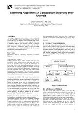
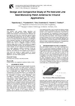
x2013 ISSN 2249 0868 Foundation of Computer Sci ence FCS New York USA Volume 1 x2013 No 5 F e b r uary 2012 x2013 wwwijaisorg 21 Design and C omparative Stu dy of Pin feed and ID: 115830

– ISSN : 2249 - 0868 Foundation Computer Sci ence

Share:

Link:

Embed:

Download Presentation from below link

Download Pdf The PPT/PDF document "International Journal of Applied Informa..." is the property of its rightful owner. Permission is granted to download and print the materials on this web site for personal, non-commercial use only, and to display it on your personal computer provided you do not modify the materials and that you retain all copyright notices contained in the materials. By downloading content from our website, you accept the terms of this agreement.


Presentation Transcript

International Journal of Applied Information Systems (IJAIS) – ISSN : 2249 - 0868 Foundation of Computer Sci ence FCS, New York, USA Volume 1 – No. 5 , F e b r uary 2012 – www.ijais.org 21 Design and C omparative Stu dy of Pin feed and Line feed Microstrip Patch Antenna for X - band Applications 1 Rajeshkumar V, 2 Priyadarshini K, 3 Glory Devakirubai D, 4 Ananthi C, 5 Snekha P 1 ,2,3,4,5 Department of Electronics and Communication Engineering, 1,2,3,4,5 Karpagam Institute of Technology, Coimbatore , Tamilnadu , India ABSTRACT This research work presents design, simulation and comparison of microstrip patch antenna designed using different feed techniques . The Microstrip feed techniques are microstrip line feed, inset fe e d, coaxial feed, aperture coupled feed and proximity coupled feed. We are chosen to compare co - axial feed and microstrip line feed due to the advantage that it can be easily fabricated and simplicity in modelling as well as impedance matching. The microstrip patch antenna is designed and simulated using high frequency simulation software FEKO and it is designed to operate in X - band frequency ra nge (8GHz - 12GHz). These antennas are designed using taconic dielectric substrate with the permittivity ε r =2.2. In this analysis, we have compared the antenna parameters such as gain, impedance, reflection coefficient, VSWR and further the performance of the se two feed techniques discussed . The antenna has been designed for the range 9 - 11 GHz; hence this antenna is highly suitable for X - band applications such as satellite communication, radar, medical applications, and other wireless systems. General Terms Microstrip Patch Antenna , Line Feed, Pin Feed Keywords X - Band, Return Loss, Impedance , Radiation Pattern, VSWR 1. INTRODUCTION Modern wireless communication system requires low profile, light weight, high gain, and simple structure antennas to assure reliability, mobility, and high efficiency characteristics [ 1, 2] . The key features of a microstrip antenna are relative ease of construction, light weight, low cost and either conformability to the mounting surface or, an extremely thin protrusion from the surface [ 2 , 3 ] . This antenna provides all of the advantages of printed circuit technology. These advantages of microstrip antennas make them popular in many wireless communication applications such as satellite communication, radar, medical applications, etc [3] . C hoosin g the design parameters (dielectric material, height and frequency, etc) is important because antenna performance depends on these parameters. Radiation performance can be improved by using proper design structures. The use of high permittivity substrates can miniaturi ze microstrip antenna size. Thick substrates with lower range of die lectric offer better efficiency and wide bandwidth but it requires larger element . An d it depends on the feeding technique the parameters like VSWR return loss bandwidth will vary [1] . This research provides a way to choose the effective feeding technique between transmission lines and Microstrip patch antenna . It also compares the characteristics of pin feed and line feed techniques. By comparing the antenna parameters the best feeding technique will be selected for the design of microstrip patch array antenna. These designed antennas are potential candidate for the X - band wireless applications due to the simplicity in structure, ease of fabrication, high gain and high efficiency [4] . Var ious parameters of the microstrip patch antennae, design considerations, performance of different feed technique s are discussed in the subsequent sections. 2. MICROSTRIP PATCH ANTENNA Microstrip antenna consists of very small conducting patch built on a ground plane separated by dielectric substrate. The patch is generally made of conducting material such as copper or gold and can take any possible shape [1] . The radiating patch and the feed lines are usually pho to etched on the dielectric substrate. The conducting patch, theoretically, can be designed of any shape, however rectangular and circular configurations are the most commonly used [1 , 6 ] . Some of the other configurations used are complex to analyze and require large numerical computations. In its most fundamental form, a microstrip patch antennae consist of a radiating patch on one side of a dielectric substrate which has a ground plane on the other side [1 ] is illustrated in figure 1. Fig 1: Structur e of Microstrip Patch Antenna Microstrip patch antennae radiate primarily because of the fringing fields between the patch edge and the ground plane. For a rectangular patch, the length L of the patch is usually 0.3333λ0 < L < 0.5 λ0 , where λ0 is the free space wavelength [ 1 , 9 ] . The patch is selected to be very thin such that t << λ0 (where t is the thickness of patch). The height h of the dielectric substrate is usually 0.003 λ0 ≤ h ≤ 0.05 λ0. The dielectric constant of the substrate is typically in the range 1.2 ≤ εr ≤ 12. International Journal of Applied Information Systems (IJAIS) – ISSN : 2249 - 0868 Foundation of Computer Sci ence FCS, New York, USA Volume 1 – No. 5 , F e b r uary 2012 – www.ijais.org 22 3. FEED TECH N IQUES Microstrip patch antennae can be fed by a variety of different methods [1] . The four most popular feed techniques used for the microstrip patch are  Microstrip line feed  Pin feed  aperture coupling  proximity coupling In this paper line feed and pin feed schemes are analyzed and compared using FEKO . 3.1 Microstrip Line Feed In this type of feeding technique, a conducting strip connected directly to the edge of the microstrip patch. The conducting strip is smaller in width as compared to the pat c h and this kind of feed arrangement has the advantage that the feed can be on the same substrate to provide a planar structure [6 , 7 ] . T his is an easy feeding scheme, since it provides ease of fabrication and simplicity in modeling as w ell as impedance matching. However as the thickness of the dielectric substrate being used, increases, surface waves and spurious feed radiation also increases, which hampers the bandwidth of the antenna [7] . The feed radiation also leads to undesired cross polarized radiation. Figure 2 shows a with microstrip line feed from the side of the patch. Fig 2: Typical Microstrip Line Feed However, t his method of feeding is very widely used because it is very simple to design and analyze, and very e asy to manufacture. Figure 3 show s rectangular patch antenna with microstrip line feed. Fig 3: Microstrip Patch Antenna with Line Feed 3.2 Coaxial Feed (Pin Feed) The Coaxial feed or pin feed is a very common technique used for feeding Microstrip patch antennas. The inner conductor of the coaxial connector extends through the dielectric and is soldered to the radiating patch, while the outer conductor is connected to the ground plane. The main advantage of this type of feeding scheme is that the feed can be placed at any desired location inside the patch in order to match with its input impedance [ 7 , 10 ] . This feed method is easy to fabricate and has low spurious radiation. However, its ma jor disadvantage is that it provides narrow bandwidth and is difficult to model slice a hole has to be drilled in the substrate and the connector protrudes outside the ground plane, thus not making it completely planar for thick substrates (h>0.02 λ0) [1] . Also, for thicker substrates, the increased probe length makes the input impedance more inductive, leading to matching problems [7 , 8 ] . Fig 4: Micr o strip Patch Antenna with Coaxial Feed 4. DESIGN CONSIDERATIONS Microstrip patch antenna consist s of very thin metallic strip (patch) placed on ground plane where the thickness of the metallic strip is restricted by t<< λ0 and the height is restricted by 0. 0003λ0 ≤ h ≤ .05λ 0 . The microstrip patch is designed so that its radiation pattern maximum is no rmal to the patch. For a rectangular patch, the length L of the element is usually λ0 /3