/
VSAT 1.2 Meter – Enhanced Training Card VSAT 1.2 Meter – Enhanced Training Card

VSAT 1.2 Meter – Enhanced Training Card - PowerPoint Presentation

tawny-fly
tawny-fly . @tawny-fly
Follow
350 views
Uploaded On 2018-09-18

VSAT 1.2 Meter – Enhanced Training Card - PPT Presentation

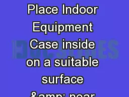
VSAT Assembly 1 Place Indoor Equipment Case inside on a suitable surface near an AC power source Ensure area is well ventilated to prevent overheating 2 Ensure Indoor Equipment alternating current AC breaker on rear panel ID: 669635

antenna amp equipment case amp antenna case equipment cable power pedestal reflector feed indoor switch turn secure place panel

Share:

Link:

Embed:

Download Presentation from below link

Download Presentation The PPT/PDF document "VSAT 1.2 Meter – Enhanced Training Car..." is the property of its rightful owner. Permission is granted to download and print the materials on this web site for personal, non-commercial use only, and to display it on your personal computer provided you do not modify the materials and that you retain all copyright notices contained in the materials. By downloading content from our website, you accept the terms of this agreement.


Presentation Transcript

Slide1

VSAT 1.2 Meter – Enhanced Training Card

VSAT Assembly 1. Place Indoor Equipment Case inside on a suitable surface near an AC power source. Ensure area is well ventilated to prevent overheating. 2. Ensure Indoor Equipment alternating current (AC) breaker on rear panel and BOTH ANTENNA / RF Equipment switches on front panel are set “OFF” 3. Place Pedestal, Reflector & RF Equipment Cases outdoors within 114 ft. of the Indoor Equipment Case. 4. Open Pedestal Case with front facing the Equator and turn POWER OFF. 5. Attach outriggers to each end of the Pedestal Case and level the pedestal. 6. Remove IFL cable reel & place within six feet of the Indoor Equipment Case. 7. Roll out the IFL cable reel & connect to the control box on the antenna pedestal, then connect IFL to the rear panel of the Indoor Equipment Case. Align the multi-pin as straight as possible to avoid damage to the pins. 8. Connect the GFI Power Cord to the rear panel of the Indoor Equipment Case, plug to an AC power source & press RESET button (large button). 9. At rear panel of Indoor Equipment Case, turn AC circuit breaker to “ON”.10. At front panel of Indoor Equipment Case, turn Antenna Power Switch to the “ON” position (Out & UP). Leave RF Power Switch “OFF”. 11. At the Pedestal Case, turn Pedestal POWER switch at the control box to the “ON / UP” position and WAIT 10 Seconds. 12. Press pedestal “DEPLOY” switch “UP” for 3 seconds or until the antenna pedestal arm starts to move then release. (The antenna pedestal rises to a vertical position ready for reflector mounting, approx. 2 minutes).13. When arm stops moving turn the POWER switch on the control box “OFF”. 14. Assemble reflector halves at the Reflector Case using quick release levers.15. Push alignment locking pins through & into the bottom antenna portion with handle in up position. Rotate lever inward 90 degrees & lock lever down.16. Place the assembled 1.2 meter dish facing up on a flat clean surface.17. Connect the antenna feed boom to the top bracket of the reflector and secure using the T-pin.18. Secure feed struts to the reflector and the boom using the slide lock collars.19. Carefully remove the Feed Horn assembly from the RF Equipment Case & verify the correct LNB is installed - then set Feed Horn polarization.20. Connect the Feed Horn using the alignment pins on the antenna feed boom and secure with the captive thumbscrew. (Remove & store feed horn cover)21. Connect the red TX cable to the BUC & the blue RX cable to the LNB.22. Place the assembled reflector onto the Antenna Pedestal mounting wedge.23. Secure the Antenna Reflector in place using the four “1/4 turn fasteners”.24. Connect the Feed Boom Cable to the Antenna Pedestal Cable. Ensure the the multi-pin connectors are aligned.25. Secure the cable on the support bracket at the back of the reflector. 26. Set POWER switch at Control Box to “ON” & check for green illumination.27. Begin Software Satellite Signal Acquisition.

VSAT Disassembly1. Close Internet Explorer and all other open programs.2. Click “Shutdown” on ViewSAT Setup Screen Software Window to perform a soft shutdown.3. Click “Yes” at the “confirm shutdown” prompt.4. Turn “OFF” (Out & Down) the RF Switch located at the front panel of the Indoor Equipment Case & then click “OK” at the screen prompt.5. Close ViewSAT by clicking the “X” in the upper right hand corner.6. Click “OK” on the Exit Program Window then shutdown & secure laptop. 7. Once the reflector dish stops moving, set the POWER switch at the control box to “OFF.” WARNING: Do not disconnect any cable with power applied.8. Unwrap & disconnect the cable from the back of the reflector.9. Secure the Antenna Pedestal cable in the stow clamp.10. Remove the assembled antenna dish and place on a flat clean surface.11. On the feed horn assembly, disconnect the red TX cable from the BUC and blue RX cable from the LNB.12. Remove the Antenna Feed Horn from the Antenna Feed Boom by turning the captive thumbscrew counterclockwise.13. Disconnect the struts from reflector & boom using the slide lock collars.14. Remove T-pin from the reflector & lift feed boom from the top bracket.15. Place the assembled dish in the reflector case bottom half first. (i.e. side where the pressure release valve is).16. Separate the two halves of the dish using the Quick Release Levers.17. Place top half of dish (side with notch) in the foam cut-out facing up.18. Turn “ON” Antenna POWER switch at the pedestal control box.19. Press & hold DEPLY/STOW switch to STOW for 3 seconds or until the antenna pedestal arms starts to move. (Power should be “ON” at Indoor Equipment Case at this time).20. After the Antenna Pedestal Arm stops moving, set the pedestal Control Box POWER switch to “OFF.”21. Return to the front panel of the Indoor Equipment Case & turn the Antenna Power switch to the “OFF” position (Out & DOWN).22. Turn “OFF” the AC circuit breaker at rear of Indoor Equipment Case.23. Disconnect IFL cable connector from the Antenna Pedestal control box.24. Loosen the adjustable feet of the outriggers & remove the outriggers.25. Disconnect IFL cable from the rear panel of Indoor Equipment Case.26. Rewind the 6-foot section of IFL cable onto the side of the cable reel & secure with the bungee cord.27. Wind the IFL cable onto the reel & secure to reel with bungee cords.28. Disconnect the GFI/AC power cord from Indoor Equipment Case & external power source and place in the RF Equipment Case.29. Disconnect all input / user cables and attach Indoor Equipment Case end covers and secure latches.30. Conduct an inventory and inspect all cases & secure all latches.

Safety

1. DO NOT stand in front of or placeany portion of your body between theFeed Boom and the Antenna Reflector as shown figure 1 above. Doing so may cause serious injury to the eyes or any exposed area.2. Do not disconnect any cable withpower applied.3. Keep hands clear of the IFL cable reel when extending/retrieving cables. 4. Use safe lift and carry procedures when handling VSAT cases. Eachcase requires a two-person lift andcarry at a minimum.

Begin Software Satellite Signal Acquisition

1. Turn “ON” (Out & UP) the RF Switch to start the initialization process. Wait approximately one minute for the Modem to initialize. 2. Modem initialization is complete when “RX” & “NET” LED shows flashing or solid amber on the front panel of the Modem.3. Open the laptop tray cover by turning the two silver knobs counterclockwise & pull the laptop out by the handle to lock tray.4. Turn on Laptop Computer and logon using the provided username _________ and password __________ .5. Double click the “ViewSAT” icon on the Windows desktop. 6. Click “Login” button (no password is required for User). 7. Select the “Startup System” button from the Setup tab.8. Select “Yes” at the Confirm Startup prompt.9. Select “OK” at Assemble Hardware prompt.10. Select “OK” at LNB Selection prompt (ensure correct LNB connected)11. Select “Yes” and the Auto Acquisition process will begin. 12. Startup is complete when the startup bar is complete & the IP Net icon on the Status window turns green.13. Open Internet Explorer - default address is: https://www.us.army.mil14. If the AKO website is not working, try another secure website (https).

AC

: Alternating CurrentACU: Antenna Control UnitBUC: Block-Up ConverterGFI: Ground Fault InterrupterGPS: Global Positioning SystemIFL: Inter-Facility LinkIP: Internet ProtocolLNB: Low Noise BlockdownRF: Radio FrequencyRTU: Remote Terminal UnitRX: ReceiveTX: TransitVoIP: Voice over Internet Protocol

Acronyms

WARNING

DO NOT stand in front of or place any portion of your body between the Feed Boom Assembly and the Antenna Reflector. It may cause serious injury to the eyes or any part of the body due to radiation.

Figure 1.

WARNING

: DO NOT Stand in Front of Reflector during Operation.

VSAT Equipment Inventory Checklist

Case

Component / Contents

Qty

Indoor Equipment

iDirect Satellite Modem

1Laptop1TracStar ACU1Reusable Fan Filters8Antenna PedestalAntenna Pedestal1Hand Crank1Control Box1Outriggers2RF EquipmentGFI / AC Power Cord1Antenna Feed Horn w/LNB# 21IFL Cable Reel 120ft. 1LNB # 11LNB # 31Compass/Inclinometer1CD Binder w/ Quick Ref Cards1Draft CSS VSAT Ref Guide1VoIP Phone2Handset2AC Power Cord2DC Power Supply28 ft. and 25 ft. Ethernet Cable2Footstand2RJ-45 Coupler2Reflector2-piece 1.2 M - E Reflector1Antenna Feed Boom1Antenna Feed Support Struts2

VSAT 1.2 Meter - Enhanced

VSAT Transport Cases

Enhanced V2