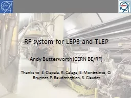
/
RF system for TLEP Andy Butterworth, Erk Jensen RF system for TLEP Andy Butterworth, Erk Jensen

RF system for TLEP Andy Butterworth, Erk Jensen - PowerPoint Presentation

telempsyc
telempsyc . @telempsyc
Follow
342 views
Uploaded On 2020-06-23

RF system for TLEP Andy Butterworth, Erk Jensen - PPT Presentation

Thanks to E Ciapala R Calaga E Montesinos O Brunner P Baudrenghien S Claudet D Nisbet 4 th TLEP3 Workshop 05042013 Overview RF requirements total accelerating voltage beam power ID: 783794

beam power mhz cavity power beam cavity mhz cavities gev tlep total load hom energy number current lep2 length

Share:

Link:

Embed:

Download Presentation from below link

Download The PPT/PDF document "RF system for TLEP Andy Butterworth, Erk..." is the property of its rightful owner. Permission is granted to download and print the materials on this web site for personal, non-commercial use only, and to display it on your personal computer provided you do not modify the materials and that you retain all copyright notices contained in the materials. By downloading content from our website, you accept the terms of this agreement.


Presentation Transcript

Slide1

RF system for TLEP

Andy Butterworth, Erk Jensen

Thanks to E. Ciapala, R. Calaga, E. Montesinos, O. Brunner, P. Baudrenghien, S. Claudet, D. Nisbet

4

th TLEP3 Workshop 05.04.2013

Slide2

Overview

RF requirementstotal accelerating voltagebeam powerTechnologyCavitiesPower couplersHigher order mode

dampingPower sources and efficiencyLow level RF & feedbacksConclusions

Slide3

RF requirements: voltage

replace the energy lost U0 at each turn by synchrotron radiationtotal power needed by the beam = U0

x Ibeammaintain longitudinal focusing with sufficient momentum acceptance

||max,RF

to keep a good beam lifetime, giventhe equilibrium energy spread due to quantum excitation/radiation damping (quantum lifetime)the energy spread (tail) due to beamstrahlung

Strongly dependent on beam energy

Slide4

RF voltage requirement is defined by:

Accelerator ring: acceptable quantum lifetime (very steep function of V

RF)

Collider ring: momentum acceptance needed to cope with beamstrahlung

3.0% for TLEP @ 120 GeV4.5% for TLEP @ 175 GeVRF voltage TLEP (704 MHz)

U0 = 9

.3

GeV

p

= 1.0 x 10

-5

E

0

= 175

GeV

J

z = 1.0fRF = 704 MHz

Energy [GeV]VRF [GV]for τq = 100hVRF [GV]for δmax,RF1202.22.71759.711.2

|

|max,RF vs VRF

M. Zanetti (MIT)

4.5% gives some margin

4.5%

Slide5

General considerations

RF frequency:higher is better, for short bunch length (hourglass effect)but higher frequency components limited in

power handlingGradient:higher is better: space, cost

but tradeoff with cryogenic powerPower dissipation =

But lose

quadratically

on

power

dissipation per

cavity

Also lose because of

decrease

in Q

0

Gain linearly on number of

cavities

Good choice: 720 MHz or 802 MHz!

Slide6

General considerations (2)

Higher order mode power:cavity loss factors, bunch length, bunch charge, beam current

power limits of HOM dampingbeam break-up from transverse modes…RF power sources:klystrons, IOTs, solid state amplifiers?

available power, efficiency, cost

Slide7

Cavities:

704

MHz

eRHIC

/SPLBNL 5-cell 704 MHz test cavity(A. Burill, AP Note 376, 2010)

BCP

only

SPL/ESS design value

2.0 x 10

10

@ 20MV/m

700 MHz seems good compromise between high

f

RF

,

power handling, gradient and Q

0

First

cavities, lots of room for improvementAssume SPL/ESS design valuesSPL type cryomodule

(4-cavity prototype)

Slide8

RF in numbers: TLEP 175 GeV

704 MHz 5-cell

Gradient [MV/m]

20

Active length [m]

1.06

Voltage/cavity [MV]

21.2

Number of cavities

567

Number of

cryomodules

71

Total

cryomodule

length [m]

902

cf. LEP2: 812 m

cf. LHC

cryoplant capacity @ 1.9K of

18 kWInput power couplers at 700 MHz for these power levels?

RF power per cavity [kW]

176

Matched

Q

ext

5.0E+06

R/Q [

linac

ohms]

506

Q

0

[

10

10

]

2.0

Dynamic

h

eat load

per cavity [W]

44.4

Total

dynamic heat load

[kW]

25.2

V

RF

= 12 GV

P

beam

= 100 MW

Slide9

700 MHz power couplers

CEA Saclay HIPPI water cooled coupler (SPL/ESS)tested up to 1.2 MW 10

% duty cycle in travelling wave, and 1 MW in standing waveCERN SPL air-cooled single window coupler2 designs currently under test: cylindrical and planar disk windows

design goal: 1 MW 10% duty cycle for SPLcylindrical window design uses LHC coupler ceramic window with tapered outer conductorLHC windows are routinely tested to

> 500 kW CW

Cylindrical

ceramic window

Coaxial disk

ceramic window

E. Montesinos

Slide10

700 MHz power couplers

Latest R&D results

High

average power air cooled couplers

(CERN BE-RF-PM)

10

0 kW average power in

t

ravelling

wave mode

Awaiting results in standing

w

ave

Cylindrical window :

TW: 1000 kW 2 ms 20 Hz

SW: 550 kW 500

μ

s

8 Hz

Coaxial disk window :

TW: 1000 kW 2 ms 50Hz

SW: 1000 kW 1.5 ms 20 Hz

40 kW average power

Limited by arcing on air side of window

Improvements underway in window air flow and screen at braze

Slide11

TLEP 120 GeV option?

704 MHz 5-cell

Gradient [MV/m]

20

Active length [m]

1.06

Voltage/cavity [MV]

21.2

Number of cavities

284

Number of

cryomodules

36

Total

cryomodule

length [m]

457

cf. LEP2: 812 m

cf. LHC

cryoplant capacity @ 1.9K of

18 kWVery high power per cavity: will be limitation on beam current and luminosity!

RF power per cavity [kW]

352

Matched

Q

ext

1.7E+06

R/Q [

linac

ohms]

506

Q

0

[

10

10

]

2.0

Dynamic

h

eat load

per cavity [W]

44.4

Total

dynamic heat load

[kW]

12.6

V

RF

= 3 GV

P

beam

= 100 MW

200

57 MW

Slide12

Top-up injector ring

V

RF

≥ 9.7 GV(only for quantum lifetime)SR power very small(beam current ~ 1% of collider ring)

Average cryogenic heat load very small(duty cycle < 10%)Power is dominated by ramp acceleration:for a 1.6 second ramp length:

TLEP-t

Beam current [mA]

0.054

Energy swing [

GeV

]

155

Max. SR power/cavity [kW]

6.2

Acceleration power [kW]

18

Max. power per cavity [kW]

24

Well within our 200 kW budget

Slide13

Higher order mode power

R. Calaga

Challenge: HOM

powers in the kW range to remove from the cavity at

2 K

k

||

= 8.19 V/

pC

k

||

= 2.64 V/

pC

Cavity loss factors

TLEP-H

TLEP-t

Beam current [mA]

48.6

10.8

Num. bunches

160

24Bunch charge [nC]

41

60HOM power

(704 MHz cavities) [kW]5.20.85

HOM power

(1.3 GHz cavities) [kW]

16.1

5.3

Average

P

HOM

= k

||

.

Q

bunch

.I

beam

Slide14

HOM power “league table”

Project

Beam current [mA]

Average HOM power per cavity [W]

CEBAF 12GeV0.10

0.05

Project X

1

0.06

XFEL

5

1

SPL

40

22

APS SPX

100

2,000

BERLinPro100150

KEK-CERL

100185

Cornell ERL100200

eRHIC

300

7,500

KEKB

1,400

15,000

After M.

Liepe

, SRF2011

TLEP-H

704 MHz

49

5,200

TLEP-t 704

MHz

11 850

Slide15

HOM ports

FPC port

BNL3

cavity optimized for high-current

applications such as

eRHIC

and SPL.

Three antenna-type HOM couplers attached to large diameter beam pipes at each end of the cavity provide strong damping

A two-stage high-pass filter rejects fundamental frequency, allows propagation of HOMs toward an RF load.

HOM high-pass filter

f

= 703.5MHz

HOM couplers: 6 of antenna-type

Fundamental

supression

: two-stage high-pass filters

E

acc = 20 MV/mDesign HOM power: 7.5 kW5-cell SRF cavity with strongHOM damping for eRHIC at BNLM. Tigner, G. Hoffstaetter, SRF2011, W. Xu et al, SRF2011

Slide16

RF power sources

“Super-power” klystrons at 700 MHz

Multiple cavities per klystron4 for collider ring?

16 or more for accelerator ring?cf. 8 in LEP2

Type

Frequency

(MHz)

Output

Power

(kW)

Efficiency

(%)

VKP-7952B

704

1000

65

Type

Frequency

(MHz)

Output

Power

(kW)

Efficiency

(%)TH2178508.6

120062

Type

Frequency

(MHz)

Output

Power

(kW)

Efficiency

(%)

E3732

508.6

1200

63

E37701

*

1071.8

1200

63

LEP2 SC RF unit:

4 cavities per

cryomodule

, 8 cavities per klystron

Slide17

Energy efficiency

High voltage power converterthyristor 6 pulse: 95%AC power quality, DC ripple @ multiples of 50 and 300 Hzswitched mode: 90%lower

ripple on the output, and/or smaller sizeKlystron: 65%if run at saturation as in LEP2i.e. no headroom for RF feedbackRF distribution losses: 5 to 7%waveguides, circulators

Overall RF efficiency (wall to beam

) between 54% and 58% without margin for RF feedbackFor comparison: CLIC wall to drive beam: 55%

Slide18

LLRF: instabilities and feedbacks

Is fast RF feedback necessary?

LEP2: slow scalar sum feedback acting on the klystron modulation anode, with the klystrons operated at saturation for maximum

efficiencyif the detuning due to beam loading is sufficiently large it can drive

coupled bunch modes however: frev = 3750 Hz, fs = 430 Hz, cavity BW = 100 Hz 

cavity BW << frev –

f

s

Fast RF feedback incompatible with klystron operation in saturation!

Microphonics

/

ponderomotive

oscillations

due to Lorentz detuning driving mechanical resonances

problem at LEP2: “cured” by cavity detuning

better handled by feedback on

Piezo

tuners

Beamloading: “second Robinson” instabilityloss of longitudinal focusing due to large detune angle under strong beamloadingoccurs at low RF voltage with high beam currentseen in LEP2 at injection energycured by using fast RF feedback on a few RF stationsan issue if we don’t have top-up injectionBecomes unstable when VG is in anti-phase with IB

Slide19

Cryogenics

Estimate based on LHC figures for cryogenic power consumption (900 W/W @ 1.9 K) to compensate fundamental frequency dynamic load only:

Beam

energy [GeV

]175

120

Number of cavities @ 20 MV/m

567

284

Total

dynamic heat load

[kW]

25.2

12.6

Power consumption [MW]

22.7

11.3

Beam

energy [

GeV

]

175

120

Power consumption [MW]

34

17

But we also have to take into account

static heat loads (~1 W/cavity cf. SPL estimate?)

HOM dissipation in cavity

overhead for cryogenics distribution etc.

Quick estimate: dynamic load x 1.5 (as suggested by S. Claudet) gives:

Slide20

Total power consumption

For TLEP @ 175 GeV with 100 MW of beam power:

Wall-plug power [MW]

η

= 54%

η

= 58%

RF (collider ring)

185

172

RF (accelerator ring)

1

1

Cryogenics (collider ring)

34

34

Cryogenics (accelerator ring)

4

4Total RF +

cryo224

211

wall-plug  beam η44.6%

47.4%

Wall-plug power [MW]

η

= 54%

η

= 58%

RF

106

99

Cryogenics

12

12

Total RF +

cryo

118

111

wall-plug

 beam

η

48.3%

51.3%

For TLEP @ 120

GeV

, the figure would be at least:

(minimal system limited to 57 MW beam power)

Compare LEP2 experience: 42%

(F. Zimmermann this morning)

Slide21

Conclusions

An RF system based on 700 MHz SC cavity technology such as being developed for eRHIC, SPS, ESS seems to be a good choice.ongoing R&D at BNL, CERN, ESS for 704 MHz cavities and components

802 MHz synergetic with SPS and LHC harmonic systems and LHeCfundamental power couplers look possible at 200 kW CWeRHIC HOM damping scheme promises sufficient performancehigh-power klystrons availableRF wall

-plug to beam efficiency around 54 – 58% (w/o cryo)

total power consumption for 175 GeV around 220 MW including cryogenics, resulting in efficiency around 48 – 51%.Open questions and R&D necessaryfundamental power couplers: R&D ongoingHOM damping scheme: study neededlow level RF & feedback requirements: study neededconstruction cost?

Slide22

Thank you for your attention!

Slide23

Backup slides

Slide24

SPS 800 MHz TWC prototype feedback board

G. Hagmann BE-RF-FB

designer

Slide25

LEP2 SC RF system

* Plus 56 copper cavities (130 MV) driven by

8

klystrons

RF frequency352 MHz

Number of cavities *288

Total accelerating voltage *

3500 MV

Number of klystrons *

36

Total

cryomodule

length

812 m

Cavities per klystron

8

Average (nom.) power per klystron

0.6 (1.3)

MWAverage power per cavity90 kWCircumference26.7 kmBeam energy104.5 GeVEnergy loss per turn3.4 GeVBeam current5 mA

Synchrotron radiation power

17 MWAvailable cooling power

53 kW @ 4.5K

Slide26

LEP2 SC RF system

Design gradient 6 MV/m

1998

2000

1999

* Plus 56 copper cavities (130 MV) driven by 8 klystrons

RF frequency

352 MHz

Number of cavities *

288

Total accelerating voltage *

3500 MV

Number of klystrons *

36

Total

cryomodule

length

812 m

Cavities per klystron

8

Average (nom.) power per klystron

0.6 (1.3)

MW

Average power per

cavity

90 kW

Circumference

26.7 km

Beam energy

104.5

GeV

Energy loss per turn

3.4

GeV

Beam current

5 mA

Synchrotron radiation

power

17 MW

Available cooling power

53 kW @ 4.5K

Slide27

Temperature: Why 2K not 4.5?

RF surface resistance

R

surf

= Rres + RBCS

I

ncreases with frequency

Residual resistance (impurities, trapped flux, etc.)

BCS surface resistance

I

ncreases with temperature

Slide28

Gradient and dynamic heat load

Power dissipation =

R/Q depends only on cavity geometry

Q

0

depends on losses in cavity walls

Shorter RF sections

Lower Q

0

, higher dissipation

Q-slope

margin for

microphonics

etc.

Slide29

LEP2 vs. TLEP SC RF systems

* Plus 56 copper cavities (130 MV) driven by 8 klystrons

LEP2

TLEP

Circumference

26.7 km

80 km

Beam energy

104.5

GeV

175

GeV

Energy loss per turn

3.4

GeV

9.3

GeV

Beam current

5 mA 5.4 mASynchrotron radiation power22 MW100 MW

RF frequency352 MHz

700 MHzTotal accelerating voltage 3500 MV *

12 GVNominal gradient6 MV/m20 MV/m

Number of cavities *288 *

567Number of cryomodules72

71Number of klystrons36 *

142

Total

cryomodule

length

812 m

902 m

Cavities per klystron

8

4

Average (nom.) power per klystron

0.6 (1.3)

MW

0.7 (1.0)

Average power per

cavity

90 kW

176 kW

Slide30

Parameters: LEP3 (27 km ring) and TLEP (80 km ring)

LEP2

LEP3

TLEP-Z

TLEP-HTLEP-t

beam energy

E

b

[

GeV

]

104.5

120

45.5

120

175

circumference [km]

26.7

26.7808080beam current [mA]4

7.2

118024.3

5.4#bunches/beam

4

42625

80

12

#e

/beam [10

12

]

2.3

4

2000

40.5

9

bending radius [km]

3.1

2.6

9

9

9

partition number J

ε

1.1

1.5

1

1

1

momentum comp. α

c

[10

−5

]

18.5

8.1

9

1

1

SR power/beam [MW]

11

50

50

50

50

Δ

E

SR

loss

/turn [

GeV

]

3.41

6.99

0.04

2.1

9.3

V

RF,tot

[GV]

3.64

12

2

6

12

δ

max,RF

[%]

0.77

4.2

4

9.4

4.9

f

s

[kHz]

1.6

3.91

1.29

0.44

0.43

E

acc

[MV/m]

7.5

20

20

20

20

eff. RF length [m]

485

600

100

300

600

f

RF

[MHz]

352

1300

700

700

700

δ

SR

rms

[%]

0.22

0.23

0.06

0.15

0.22

σ

SR

z,rms

[cm]

1.61

0.23

0.19

0.17

0.25

Slide31

Why not 1.3 GHz?

ILC cavity specifications:

(mounted)

BCP + EP

Gradient

Q

0

Vertical test (bare cavity)

35 MV/m

> 0.8 x 10

10

Mounted in

cryomodule

31.5 MV/m

> 1.0 x 10

10

Test results for eight 1.3 GHz 9-cell TESLA cavities achieving the ILC specification (DESY)

Slide32

RF power per cavity [kW]

173

216

Matched

Q

ext

2.4E+06

3.0E+06

R/Q [

linac

ohms]

1036

1036

Q

0

[

10

10

]1.51.3Dynamic heat load per cavity [W]27.750.0

Total dynamic heat load [kW]

16.123.2

LEP3

1300 MHz 9-cell

Gradient [MV/m]

20

25

Active length [m]

1.038

1.038

Voltage/cavity [MV]

20.76

25.95

Number of cavities

579

463

Number of

cryomodules

72

58

Total

cryomodule

length [m]

927

737

1.3

G

Hz (TLEP 175

GeV

)

cf. 1.06 m for 704 MHz 5-cell

Input power couplers @ 1.3 GHz ??

V

RF

= 12 GV

P

beam

= 100 MW

Slide33

1.3 GHz power couplers

TTF-III couplers tested to 5 kW in CW

8kW with improved cooling (BESSY)

Some higher power adaptations for ERL injectors

e.g. Cornell 60 kW CWV. Vescherevitch, ERL’092 couplers per 2-cell cavity in ERL injector

cryomoduleGradient: 5-15MV/m

Beam current: 100 mA

power

coupler

for 1.3 GHz 200 kW CW looks challenging…

Slide34

2 K Heat Loads (per β

=1 cavity)

Operating conditionValue

Beam

current/pulse lenght40 mA/0.4 ms beam pulse 20 mA/0.8 ms beam pulse

cryo

duty cycle

4.11%

8.22%

quality factor

10 x 10

9

5 x 10

9

accelerating field

25 MV/m

25 MV/m

Source

of Heat Load

Heat Load @ 2K (per cavity)

Beam

current/pulse lenght40 mA/0.4 ms beam pulse 20 mA/0.8 ms beam pulse

dynamic heat load per cavity

5.1 W

20.4 W

static losses

<1 W

(tbc)

~

1 W

(tbc)

power coupler loss at 2 K

<0.2 W

<0.2 W

HOM loss in cavity at 2 K

<1

<3 W

HOM coupler loss at 2 K (per

coupl

.)

<0.2 W

<0.2 W

beam loss

1 W

1 W

Total @

2 K

8.5 W

25.8 W

Slide35

LHC cryogenic plant capacity

For LEP3 it would be very advantageous if the cryogenic power required for the RF could be supplied by the existing LHC cryogenics plants

Installed refrigeration capacity in the LHC

sectors

Temperature

level

High-load

sector

(1-2,

4-5,

5-6

, 8-1)

Low-load

sector

(2-3,

3-4,

6-7

, 7-8)

50-75 K [W]33000310004.6-20 K [W]77007600

4.5 K [W]

300150

1.9 K LHe [W]2400

2100

4 K VLP

[W]430

380

20-280 K

[g.s-1]

41

27

LHC

cold compressors

(125 g/s@15mbar=1.8K) have

similar dimensions as the

CEBAF ones

(250g/s@30mbar=2.0K

)

However, piping, motors and so on would not be compatible with a factor 2 in capacity.

A

more detailed study

would

be necessary to evaluate the performance we could have if some parts would be changed (motors, bearings, valves,...)

Total wall-plug power for LHC cryogenics = 40 MW

Slide36

Total wall-plug power for LHC cryogenics = 40 MW

Carnot ~150 @ 2K

Eff. ~ 30% of Carnot