/
1961 Schroeder  and  Logan:  (‘Colorless”  Artificial  Rever 1961 Schroeder  and  Logan:  (‘Colorless”  Artificial  Rever

1961 Schroeder and Logan: (‘Colorless” Artificial Rever - PDF document

test
test . @test
Follow
389 views
Uploaded On 2015-10-12

1961 Schroeder and Logan: (‘Colorless” Artificial Rever - PPT Presentation

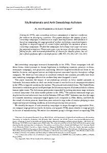
210 IRE TRANXACTIONX OlV AC145DIO NovemberDecember Before attempting the difficult task of reproducing room characteristics by delallines it is wise to recall some of the important pr ID: 158670

210 IRE TRANXACTIONX OlV

Share:

Link:

Embed:

Download Presentation from below link

Download Pdf The PPT/PDF document "1961 Schroeder and Logan: (‘Colo..." is the property of its rightful owner. Permission is granted to download and print the materials on this web site for personal, non-commercial use only, and to display it on your personal computer provided you do not modify the materials and that you retain all copyright notices contained in the materials. By downloading content from our website, you accept the terms of this agreement.


Presentation Transcript

1961 Schroeder and Logan: (‘Colorless” Artificial Reverberation 209 center speaker, the absence of a hole in the middle be- comes a rare “special case” for perhaps just one ob- serving location and perhaps not even one location. This is true regardless of the stereo recording tech- nique or number of microphones. No bridging of micro- phones can fill the hole in the center if there is no speaker there to reproduce it except sometimes for one 210 IRE TRANXACTIONX OlV AC‘DIO November-December Before attempting the difficult task of reproducing room characteristics by delal--lines, it is wise to recall some of the important properties of large rooms. THE FREQ-CEXCY RESPONSE OF LARGE Room room can be characterized by its normal modes of vibration. It has been shonrn2 that the density of modes is nearly independent of room shape and is proportional to the square of the frequency : number of modes per cps = (;;)y. Here V= the volume, c= the velocity of sound, and f the frequency. Above a certain critical frequenc~-,~ given by ~- Jc = 2000dT/V (reverberation time Tin seconds, V inm”, the density of modes becomes so high that many modes overlap. In this frequency range, which is of prime inter- est for large rooms, the concept of individual normal modes loses its practical (though not its theoretical) sig- nificance. The behavior of the room is governed by the collective action of �man- simultaneously excited and interfering modes resulting in a very irregular ampli- tude-frequency re~ponse.~,~ However, the fluctuations are so rapid (on the frequency scale) that the ear, in listening to a non-steady sound, does not perceive these irregularities.6 (The response fluctuations can be heard by exciting the rooms with a sinen-ave of slowly varying frequency and listening with one ear.) \Vhen the room response is measured using, instead of a sinewave, a �psychoacousticall- more appropriate test signal, such as narrow bands of noise, the response would indeed be much smoother. It is this apparent smoothness of a room’s frequency response x\-hich people have found particularly difficult to imitate with artificial reverberators. In this paper we shall describe electronic reverberators which have per- fectly flat amplitude-frequency responses. Thus, they not only overcome this long-standing difficulty but are in this one respect. Hen-ever, a flat frequenc~, response is not the onl?, requirement for a high-quality reverberator. Before we can hope to successfully design one, we must also know something about the transient behavior of rooms. Jfad. Phys., vol. 16, pp. 69-150: April, 1944. 2 P. 41. hlorse and IH, Bolt, “Sound \vaves in Rev. jurven von grossen Raumen, Acz~stica, vol. 4, Beiheft 2, pp. 594- 3 M. R. Schroeder, “Die $atistischen Parameter der Frequenz- 600; 1954. 4 E. C. \Vente, “Characteristics oi sound transmission in rooms,” J. Acaust. Soc. Am., vol. 7, pp. 12$!26; October, 1935. 5 13. Kuttruff und R. ThiFle, Uber die Frequenzabhangigkeit des Schalldruclrs im Rkumen, Ac~~~tica, vol. 4, Beiheft 2, pp. 614- 617; 1954. rooms,” Acustica, vol. 5, pp. 44-48; 1955. 6 A. F. Sickson and R. IV. Muncey, “Frequency irregularity in THE TRASSIENT BEHAVIOR OF ROOMS How does a room respond to excitation with a short impulse? If we record the sound pressure at someloca- tion in the room as a function of time, \x-e first observe an impulse corresponding to the direct sound which has traveled from the sound source to the pick-up point without reflection at the malls. A4fter that we see a num- ber of discrete lon--order echos which correspond to one or a few reflections at the walls and the ceiling. Grad- ually, the echo density increases to a statistical “clut- ter.” In fact, it can be shown’ that the echo density is proportional to the square of the elapsed time: 4TC3 number of echos per second = ___ 1‘ 12. The time after which the echo response becomes ;L statistical clutter depends on the width of the exciting impulse. For a pulse of width At, the critical time after which individual echos start overlapping is about t, = 5. IO-~~I~Z (V in m3). ‘Thus, for transients of I-msec duration and a volunle of 10,000 1n3 (350,000 ft3), the response is statistical for times greater than 150 msec. In this region, the concept of the individual echo loses its practical significance. The echo response is determined by the collective be- havior and interference of many overlapping ethos.* a4nother important characteristic of large “diffuse” rooms is that all modes have the same or nearly the same reverberation time and thus decay at equal rates as evidenced by a straight-line decay when plotting the sound level in decibels vs elapsed time. Still another property of acoustically good rooms is the absence of ‘(flutter” echos, ie., periodic echos re- sulting from sound waves bouncing back and forth be- tween parallel hard walls. Such periodicities in the echo response are closely associated with one-dimensional modes of sound propagation which can be avoided by splaying the walls and placing “diffusors” in the sound path. THE CONDITIOSS TO BE ~IET HY ARTIFI(:I;\L REVERBERATORS After this brief review, we are in a positioll to t‘or- mulate conditions to be met by artificial reverberators. 1) The frequency response must be flat when meas- ured with narrow bands of noise, the bandwidth corre- sponding to that of the transients in the sound to be re- verberated. This condition is, of course, fulfilled by re- akustik,” Band 1 (“Geometrische Raumaltustilc”), S. Hirzel I’erlag, 7 L. Crenler, “Die v-issenschaftlichen Grundlagen der Raum- Stuttyart, Germany, vol. 1, p. 27; 1948. * R. C. Jones, “Theory of fluctuations in the decay of sound,” J. ..lcoz~st. Sor. Avz., vol. 11, pp. 324-332; Januar:,, 1940. 1961 Schroeder and Logan: “Colorless” ArtiJicial Reuerberation verberators which have a flat response even for sinu- soidal excitation. 2) The normal modes of the reverberator must over- lap and cover the entire audio frequency range. 3) The reverberation times of the individual modes must be equal or nearly equal so that different frequency components of the sound decay with equal rates. 4) The echo density a short interval after shock ex- citation must be high enough so that individual echos are not resolved by the ear. 5) The echo response must be free from periodicities (flutter echos). In addition to these five conditions, a sixth one must be met which is not apparent from the above review of room behavior but easily violated by electronic rever- berators : 6) The amplitude-frequency response must not ex- hibit any apparent periodicities. Periodic or comb-like frequency responses produce an unpleasant hollow, reedy, or metallic sound quality and give the impression that the sound is transmitted through a hollow tube or barrel. This condition is a particularly important one because long reverberation times are achieved by circulating the sound by means of delay in feedback loops. The re- sponses of such loops, which are the equivalent of one- dimensional sound transmission, are inherently periodic and special precautions are required to make these periodicities inaudible. In the following, a basic reverberator is described which fulfills conditions l), 3) and 6) ideally. By con- necting several of these reverberating elements in series, conditions 2), 4) and 5) can also be satisfied without violating the others. TWO SIMPLE REVERBERATORS The simplest reverberator consists of a delay-line, disk, or tape-delay which gives a single echo after a de- lay time 7. Its impulse response is h(t) = 6(t - T), (1) where s(t) is the Dirac delta-function (an ideal impulse). The spectrum of the delayed impulse is H(w) = e--iwr, (2) where w is the radian frequency. The absolute value of H(w) is one. This means that all frequencies are passed equally well and without gain or loss. In order to produce multiple echos without using more (expensive) delay, one inserts the delay line into a feedback loop, as shown in Fig. 1, with gain g of magni- tude less than one (so that the loop will be stable). The impulse response, illustrated in Fig. l(b), is now an ex- ponentially decaying repeated echo: h(t) = 6(1 - 7) + g6(t - 27) + g%(t - 37) + ‘ ’ * (3) 21 1 GAIN, g (a) 1/~ 2/r FREQUENCY, f �(c Fig. 1-(a) Delay in feedback loop. (b) Impulse response. (c) Fre- quency response. Simple reverberators with exponentially decay- inc echo response. Frequency response resembles comb. The corresponding complex frequency response is H(w) e--iw7 + ge-2iwr + g2e-3iw~ + . . . , (4) or, using the formula for summing geometric series, e- iw T H(u) = ~___ - (5) 1 - ge-i.ur By taking the absolute square of H(w), one obtains the squared amplitude-frequency response: i I H(w) l2 = (6) 1 + g2 - 2g cos w7 As can be seen, 1 H(w) 1 is no longer independent of fre- quency. In fact, for w =2n~/r (n=0, 1, 2, 3, * e ), the response has maxima (for positive g) given by 1 H,,,, = - (7) 1-g and, for w= (2n+1)7r/7, minima given by 1 H,,i, = - . (8) l+g The ratio of the response maxima to minima is Ifg 1-g HmaxlHmin = - * (9) For a loop gain of g = 0.7 (-3 db), this ratio is 1.7/0.3 =5.7 or 15 db! The amplitude-frequency response of a delay in a feedback loop has the appearance of a comb with peri- odic maxima and minima, as shown in Fig. l (c). Each . . . 7 7 . . acoustic feedback stability in public address