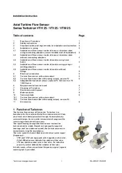
/
HFKQLFDOFKDQJHVUHVHUYHG  Installation Instruction Axial Turbine Flow Sensor Series Turbotron HFKQLFDOFKDQJHVUHVHUYHG  Installation Instruction Axial Turbine Flow Sensor Series Turbotron

HFKQLFDOFKDQJHVUHVHUYHG Installation Instruction Axial Turbine Flow Sensor Series Turbotron - PDF document

test
test . @test
Follow
469 views
Uploaded On 2015-01-15

HFKQLFDOFKDQJHVUHVHUYHG Installation Instruction Axial Turbine Flow Sensor Series Turbotron - PPT Presentation

1 Installation of flow sensor made of brass or stainless steel using connecting adaptors recommended kind of installation W57347ILUVW57347VFUHZ57360LQ57347WKH57347FRQQHFWLQJ DGDSWRUV57347LQWR57347WKH57347WXEH57361573478VH57347RQO57347D57347VXLWDEOH57 ID: 31353

Installation flow sensor

Share:

Link:

Embed:

Download Presentation from below link

Download Pdf The PPT/PDF document "HFKQLFDOFKDQJHVUHVHUYHG Installation In..." is the property of its rightful owner. Permission is granted to download and print the materials on this web site for personal, non-commercial use only, and to display it on your personal computer provided you do not modify the materials and that you retain all copyright notices contained in the materials. By downloading content from our website, you accept the terms of this agreement.


Presentation Transcript

Technical changes reserved EA-4900-E 10/20051 Installation InstructionAxial Turbine Flow SensorSeries Turbotron VTH 25 / VTI 25 / VTM 25Table of contentsPage1Function of Turbotron12Safety instructions23Important notes and requirements to installation and operation34Installation in piping34.1Installation of flow sensor made of brass or stainless steelusing connecting adaptors (recommended kind of installation)34.2Installation of flow sensor made of brass or stainless steeladaptors44.3 Installation of flow sensor made of plastics using hose44.4Installation of flow sensor made of plastics using gluing oradaptors44.5 Installation of flow sensor made of plastics without 55Electrical connection65.1Turbine flow sensor with pulse output65.2Turbine flow transmitter with analog output, version AI65.3Integrated temperature sensor (option) Pt 100/3-wire or Pt6Replacement of turbine insert67Cleaning of Turbotron78Shut-down and disposal79Materials table810Technical data810.1Turbine flow sensor with pulse output10.2Turbine flow transmitter with analog output, version AI11Dimensions91 Function of TurbotronThe turbine flow sensor of the series Turbotron is atransducer for flow rate and total flow measurement. It has VTH and VTM are equipped with magnets on the rotor.- VTI has stainless steel pins in the rotor. An inductiveIn both cases, a flow-proportional frequency signal (square Technical changes reserved EA-4900-E 10/200522 Safety instructions· Before you install the product, please read the relevant chapters of the installation instruction carefully.· The turbine flow sensor is only suitable for measuring liquid flows, on no account for measuring gasflows.· Check before installation, whether the material of the turbine flow sensor is suitable for the medium tobe monitored (see Materials Table, Chapter 9)!· You can fit the turbine flow control instrument in any position. If it is installed into vertical pipes, the flow· The arrow which is placed on the flow sensor (è) shows the only permitted flow direction.· For precise measurement, the length of the straight in - and outlet tubes must be observed (see Chap.· The internal diameter of the in - and outlet tube must correspond with the internal diameter of the flow· The flow medium to be monitored should preferably contain as few solid particles as possible. Present· Avoid absolutely the formation of gas bubbles or cavitation in the medium by taking proper measures.· The material of the instrument is not suitable for monitoring oils. The strength of the used plastic partswould be considerably reduced.· In order to clean the flow sensor of contaminations, flush the unit with water reverse to the flow direction· The instrument must not be blown out with compressed air. The turbine can be damaged.· We recommend to use only screened connection cables. Connect the shield on one side (the wire· Attention:The pick-off (Hall-Effect-Sensor or inductive proximity switch) is sealed and must not be opened.· There are special customer designs that may differ from the standard data listed in these instructions –always consider the specifications noted on the type plate. Technical changes reserved EA-4900-E 10/200533 Important notes and requirements to installation and operationObserve the following instructions in order to achieve highest-possible measurement accuracy andspecified output signal.· Before installing the turbine flow sensor flush the pipe carefully. You avoid a blocking of the turbinecaused by particles from the pipe installation.· The installation position of the flow sensor is unreserved. If it is installed into vertical pipes, the flow· The arrow which is placed on the flow sensor (è) shows the only permitted flow direction.· A straight tube in front (upstream) of the flow sensor must be retained, min 10 x DN, i.e. 25 cm. Behind· The flow medium to be measured should preferably contain as few solid particles as possible. Present· The materials of the instrument are not suitable for monitoring oils. The strength of the used plastic· Attention:The pick-off (Hall-Effect-Sensor or inductive proximity switch) is sealed and must not be opened.4 Installation in piping· Now you can install the Turbotron in the piping system which was prepared according to chapter 3.4.1 Installation of flow sensor made of brass or stainless steel using connecting adaptors (recommended kind of installation)· At first screw-in the connecting adaptors into the tube. Use only a suitable compound for sealing. Takecare that no fibrous sealing compounds get into the turbine (hemp or Teflon strip).· Now install the turbine. Make sure that the provided seals fit properly and tighten the union nuts. Technical changes reserved EA-4900-E 10/200544.2 Installation of flow sensor made of brass or stainless steel without connecting adaptorsThe turbine system fits into the Turbotron casing and is correctly positioned by the two connecting adaptors.If you do not want to use connecting adaptors, you must observe the following instructions:· Your piping system must have a collar at the outlet side of the Turbotron which prevents slipping of theturbine insert. Recommended dimensions are:Internal diameter: 25-26 mm· When installing the Turbotron, make sure that the seals fit properly.4.3 Installation of flow sensor made of plastics using hose nozzles· In the outlet of the Turbotron, there is a spacer. Remove it before installation of the hose barb.· Push the hose barb with a rotational movement into the Turbotron casing. Make sure that the O-ring isnot displaced and tighten the union nut.· Put the hose barb into the piping and fix it with suitable means, e.g. with hose band clips.4.4 Installation of flow sensor made of plastics using gluing or welding adaptors· Glue or weld at first the connecting adaptors to the piping.· Now install the turbine. Make sure that the provided seals fit properly and tighten the union nuts. Technical changes reserved EA-4900-E 10/200554.5 Installation of flow sensor made of plastics without fittings· Install the Turbotron without removing the spacer from the outlet.· Your piping system must have a collar at the outlet side of the Turbotron which prevents slipping of theturbine insert. Recommended dimensions are:Internal diameter: 25-26 mm· When installing the Turbotron, make sure that the seals fit properly. Technical changes reserved EA-4900-E 10/20056 5 Electrical connectionAttention: We recommend to use only screened connection cables. Connect the shield on one side (thewire ends) on ground.5.1 Turbine flow sensor with pulse outputThe output signal of Turbotron is a flow-proportional frequency signal. The shape of the signal is a squarewave and its amplitude corresponds approximately with the supply voltage. It is an open collector signal,NPN- or PNP-switching. The connected electronic instrument should have a loading resistance (pull-up orpull-down resistor) of 5 kW in the inlet.Schematic representationA connection is made with three leads, the supply voltage must be connected between +U and GND(ground), the output signal can be tapped between and GND. The color assignment of the supplycables can be taken from the sketch on the type plate.VTHVTMBN = brown, GN = green,WH = white, R = resistorVTI5.2 Turbine flow transmitter with analog output, version AI5.3 Integrated temperature sensor Pt 100/3-wire or Pt 1000/3-wire (option)BN = brownGN = green Technical changes reserved EA-4900-E 10/200576 Replacement of turbine insert· Dismount the flow sensor. The pick-off (Hall-Effect-Sensor or inductive proximity switch) is sealed andmust not be opened.· Press the turbine insert out of the tube piece in flow direction using a flat tool.· The turbine insert consists of two cylinders of different diameters which must never be dismounted.· Push the new insert with the small diameter to the front into the pipe section against the flow direction.· Reinstall the Turbotron in the piping. Make sure that the provided seals fit properly. Technical changes reserved EA-4900-E 10/200587 Cleaning of Turbotron· To remove dirt from the flow sensor, you should flush it with water reverse to the flow direction.· Attention:The pick-off (Hall-Effect-Sensor or inductive proximity switch) is sealed and must not be opened.· Warning:8 Shut-down and disposal· Remove the electrical connection and carry out the flow sensor.· The Turbotron unit is made of different materials (see technical data). Don't dispose the Turbotron unittogether with household waste. The official rules of your area have to be observed at disposing of theTurbotron unit. Technical changes reserved EA-4900-E 10/200599 Materials TableMaterials TypeVTH 25 MS-180VTH 25 K6-180VTM 25 MS-180VTM 25 VA-180VTI 25 MS-180VTI 25 K6-180 Pipe sectionBrass, DZRCuZn36Pb2AsPPBrass, DZRStainless steelBrass, DZRPP Turbine cagePPO Noryl GFN 3V 960 RotorPPO Noryl GFN 2V 73701 Rotor assemblyPermanent magnets, Recona 28 nickel platedStainless steel 1.4305 ShaftStainless steel 1.4436 BearingSapphire / PA Pick-offPPO Noryl GFN 1630 VBrass, DZRCuZn36Pb2AsCW602NStainless steel1.4571POM Delrin 100 P O-ring72 NBR 872 Filtering screenStainless steel1.430170 EPDM 281---Stainless steel 1.430170 EPDM 281--- HousingPA Spacer---PP---------PP 10 Technical Data10.1 Turbine flow sensor with pulse output*** additional fitting required**There are special customer designs that may differ from the standard data listed in these instructionsalways consider the specifications noted on the type plate.TypeVTHVTMVTI Material pipe sectionBrassPlasticsBrassStainlesssteelBrassPlastics Pick-offHall sensorInductive proximity switch Nominal diameterDN 25 Measurement range(1) 4...160 l/min, continuous operation max. 80 l/min Start of signal output Measurement accuracy+/- 3% of reading Reproducibility+/- 0.5% Output signal- Signal shape- Pulse rate / K-factor- ResolutionSquare signal NPN open collector65 pulses / litermASquare signalmA Pull-up-resistance5 K (recommendation) Supply voltage4.5 ... 24 VDC10 ... 30 VDC Electrical connection2 m PVC cable, screened(Tmax = 75°C)4-pin plug M12x1 Protection classIP 54 Max. medium temperature85 °C80 °C (2 bar)30°C (10 bar)85 °C60 °C60 °C (5 bar)30°C (10 bar) Nominal pressurePN10PN50PN10 Max. size of foreign particles Process connection1¼” BSP1¼” BSP1¼” BSP male*1¼” BSP Technical changes reserved EA-4900-E 10/20051010.2 Turbine flow transmitter with analog output, version AI*** additional fitting required**There are special customer designs that may differ from the standard data listed in these instructionsalways consider the specifications noted on the type plate.11 Dimensions (selection)VTH 25 MS-180 with connecting adaptorTypeVTHVTMVTI Material pipe sectionBrassPlasticsBrassStainlesssteelBrassPlastics Pick-offHall sensorInductive proximity switch Nominal diameterDN 25 Measurement range (scalingsee type plate4...20 mA corresponding to0...60 l/min,(continuous operation max. 80 l/min) Start of signal output Output signal4...20 mA Current limitapprox. 26 mA Max. current consumption30 mA Max. resistance250  against GND Residual ripple0,2 mASS over the entire range Type3 wire, galvanically not separated,common GND of power supply and output signal Power supply18...30 VDC Electrical connection4-pin plug M12x1 Protection classIP 54 Max. medium temperature85 °C80 °C (2 bar)30°C (10 bar)85 °C60 °C60 °C (5 bar)30°C (10 bar) Nominal pressurePN10PN50PN10 Max. size of foreign particles Process connection1¼” BSP1¼” BSP1¼” BSP male*1¼” BSP Technical changes reserved EA-4900-E 10/200511VTM 25 MS-180VTM 25 VA-180VTH 25 K6-180Turbine flow transmitter, version AI EA-4900-E 05/2009 EA-4900-E 05/2009 EA-4900-E 05/2009 VTH 25 MS-180VTH 25 K6-180VTM 25 MS-180VTM 25 VA-180VTI 25 MS-180VTI 25 K6-180 10 Technical Data10.1 Turbine flow sensor with pulse output**TypeVTHVTMVTI EA-4900-E 05/2009 EA-4900-E 05/2009 EA-4900-E 05/2009 5 Electrical connectionAttention: 5.1 Turbine flow sensor with pulse outputWSchematic representation VTHVTMVTI5.2 Turbine flow transmitter with analog output, version AI5.3 Integrated temperature sensor Pt 100/3-wire or Pt 1000/3-wire (option) EA-4900-E 05/2009 EA-4900-E 05/2009 EA-4900-E 05/2009 EA-4900-E 05/2009 EA-4900-E 05/2009 Installation InstructionAxial Turbine Flow SensorSeries Turbotron VTH 25 / VTI 25 / VTM 25Table of contentsPage1 Function of Turbotron