/
PYROGEN FIRE SUPPRESSION GRENADES J. Berezovsky and S. Joukov AES Inte PYROGEN FIRE SUPPRESSION GRENADES J. Berezovsky and S. Joukov AES Inte

PYROGEN FIRE SUPPRESSION GRENADES J. Berezovsky and S. Joukov AES Inte - PDF document

test
test . @test
Follow
443 views
Uploaded On 2016-04-20

PYROGEN FIRE SUPPRESSION GRENADES J. Berezovsky and S. Joukov AES Inte - PPT Presentation

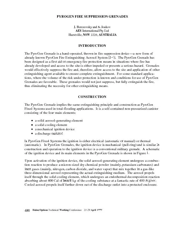
141 a serious four main elements a solid aerosolgenerating element a solid cooling element a mechanical ignition device a discharge outlets In PyroGen Fixed Systems the ignition is e ID: 286138

1-41 serious four

Share:

Link:

Embed:

Download Presentation from below link

Download Pdf The PPT/PDF document "PYROGEN FIRE SUPPRESSION GRENADES J. Ber..." is the property of its rightful owner. Permission is granted to download and print the materials on this web site for personal, non-commercial use only, and to display it on your personal computer provided you do not modify the materials and that you retain all copyright notices contained in the materials. By downloading content from our website, you accept the terms of this agreement.


Presentation Transcript

PYROGEN FIRE SUPPRESSION GRENADES J. Berezovsky and S. Joukov AES International Pty Ltd Hurstville, NSW 2220, AUSTRALIA INTRODUCTION The PyroGen Grenade is a hand-operated, thrown-in fire suppression device-a new form of already known PyroGen Fire Extinguishing Aerosol System [ 1-41, a serious four main elements: a solid aerosol-generating element a solid cooling element a mechanical ignition device a discharge outlet(s) In PyroGen Fixed Systems the ignition is either electrical (automatic or manual) or thermal (automatic). In PyroGen Grenades, the ignition device is mechanical (pull-ring) and is similar in construction and operation to the ignition device in a conventional military grenade. A schematic of the ignition device and its 1. Upon activation of the ignition device, the solid aerosol-generating element undergoes a combus- tion reaction to produce a micron-sized dry chemical powder (mainly, potassium carbonates) and inert gases (mainly, nitrogen, carbon dioxide, and water vapor) that mix together in a heat/l kg cooling substance deghec. Cooled aerosol propels itself further down out of the discharge outlet into a protected enclosure. 480 Halon Options Technical Working Conferencc 21-29 April IY9Y 1 4 h Figure 1. A schematic of the ignition device. 1 - ii split pin 2 - a rinr 3 - a sprinf 4 - ii striker 5 - ii capsule carlridge 6 ~ ii delay tube cartridgc 7 ~il b~stcr When the ring (2) is pulled out by straightening the ends of the split pin (I), the spring (3) looses the striker (4), which hits the capsule cartridge (S). delay tube (6). thus ensuring a required delay of 6-10 sec (depending on the size or the grenade), between the activation of PyroGen Grenade and the discharge of the aerosol. Ignition of the booster causes ignition of the aerosol element resulting in release of the extinguishing aerosol. EXTINGUISHING ACTION PyroGen aerosol is an exceptional fire suppressant, Primarily, the PyroGen extinguishing action is achieved by interfering chemically with the fire reaction. Two chemical mechanisms are emphasized below. I. Romovul offlunip pr-opugulio~~ r-udiculs-”c~huir~ c.irr-rirr.s” OH, H. u17d 0 in tlwflume :or10 The main component of PyroGen aerosol (potassium carbonates) is in the gaseous form. In producing potassium carricrs” OH, H, and 0, which they remove from the fire zone, thus disrupting the fire reaction. The chemical action or potassium radicals in PyroGen is similar to that of bromine radicals in halons and can be schematically represented as follows: K + OH = KOH KOH + H = K + H20 2. Recombination of,flame propagation radicals-”chain curriers” OH, H, and 0 on aerosol particle suifuce Gaseous potassium carbonates condense to a liquid and then to a solid form, producing a large number of micron-size particles. Being so small, the particles produce a large surface area, where recombination of “chain carriers” takes place: O+H=OH H + OH = HzO below which bC03 (si + hC03 (11 + KzC03 (si endothermic decomposition 2KHCQ (s) 4 KzCQ (5) + C02 (g) + HzO(,) (c) Dilution of the fire combustion zone by the aerosol cloud (additional fuel molecules cannot participate in the combustion process); physical hydrance to flame propagation (aerosol particles slow down velocity of a flame front propagation). The extremely high surface area of the micron-size aerosol particles increases the likelihood of radical recombination and heat absorbing reactions, thus ensuring rapid extinguishment with a small amount of agent. PyroGen has the lowest extinguishing concentration known among commercially available agents: flammable liquids (class B fires) are extinguished at the design factor of 100 s/m3 compared to 330 g/m3 for Halon 1301. The high rate of aerosol discharge ensures a tremendous knockdown effect thus avoiding the conventional fire damage to assets. Micron-size aerosol particles exhibit gas-like three-dimensional qualities that allow the agent to distribute rapidly throughout the enclosure and reach the most concealed and shielded locations. Homogeneous distribution is achieved in a matter of seconds, while long holding times all help to prevent fire reignition. PyroGen aerosol is suitable for the protection of a variety of potential fire hazards, including those involving flammable liquids, combustible solids, oils, and energized electrical equipment. Like all total-flooding agents, PyroGen aerosol is most effective when used in an enclosed area. PYROGEN ENVIRONMENTAL CHARACTERISTICS PyroGen does not affect earth’s ozone layer, since it does not contain chlorine or bromine in its molecular structure. The contribution of PyroGen to global warming is negligible, since the only component (carbon dioxide) of PyroGen aerosol that could contribute to global warming is present in minor quantities at normal extinguishing concentrations. Both the ODP and GWP of PyroGen are zero. 482 Halon Options Technical Working Conference 27-29 April lY99 TEST SET-UP Objective The following test was to demonstrate the ability of PyroGen Grenades to suppress fires that could occur within a small to medium-size enclosed room. The test was carried out on the test ground of Australian Defence (Melbourne. Victoria). Testing Chamber The following enclosure was used for testing: 3.8 m long. 3.8 m wide, 2.2 m high with a total internal volume of 3 1.77 m3. Natural gaps and existing uncloseable openings were used to relieve excessive pressure build up during discharge and to ensure sufficient ventilation during preburn period. Model Fires A tray (SO0 by 700 mm) with a diesel fuel and a jet fuel was centrally located on the floor to provide a Class B (flammable liquid) fire. Preburn time for diesel fuel was 2 min. Preburn time forjet fuel was 60 sec. The holding time for all fires was 3 min. Instrumentation A number of K-type thermocouples were installed to measure fire temperature (extinguishment time) and ambient air temperature in the enclosure. Thermocouple outputs were recorded by ineans of a Data Logger connected to a computer to collect data at a rate of 10 times/sec and permit the subsequent print out of fire-out temperatures and enclosure temperature curves. I'yroGen Grenades The following grenades shown in Table 1 were used for testing. Design Calculations The PyroGcn design factor refers to the mass of nonignited. aerosol-generating m' enclosure. Design factor of 100 g/m' as established for class B fires was used for design calculations. As the internal volume was 3 1.77 m- , the total quantity was calculated as 3 100g/in'x31,77m'=3,177g. Seven PyroGen Grenades MAG-SG were recommended. Halon Option\ Technical Workins Contcrcncc 27.2'9 April I999 483 TABLE 1. PYROGEN GRENADES. Parameters Mag-S/lg Mag-S/2g (one discharge outlet) (two discharge outlets) Mass of grenade, g 212s 1870 Dimensions: diameterbength, mm 100/200 75/280 Mass of aerosol element, g 500 so0 Discharge time, sec 5-7 5-7 Maximum protected volume, m3 S S Delay time between activation and 8-10 8-10 aerosol discharge, sec Operation temperature range -50 OC + SO "C Test Procedure The test procedure for all fire tests was as follows: 0 First-aid portable fire extinguishers were at hand. Grenades were in operable condition. Le., a delay 0 0 0 Test Protocol Free-Burn Test A free-bum fire test (no agent) was conducted prior to the extinguishing test to demonstrate that sufficient oxygen and amount of fuel were provided and, therefore, extinguishment was due to the action of PyroGen grenades and not through fuel consumption or oxygen depletion. Jet Fuel Pan Fire Test-7 MAG4 Grenades Experimental temperature curves are given in Figure 2. On the Figure, the first start mark corre- sponds to the activation of the first Grenade, the second start mark to the activation of the last Grenade, and the third start mark to the closure of the door. As it can be seen from the fire temp- erature curve, within 7 sec from the closure of the door, the temperature of the fire started a sharp monotonous descent indicating fire extinguishment. 484 Halon Options Technical Wnrking Confcrence 27-21, April IYY9 800 700 600 500 u ? I 400 P c : 300 zoo 100 0 0 50 100 150 200 250 300 Time sec. Figure 2. Jet fuel pan fire test-7 MAG-S grenades Diesel Fuel Pun Fire Test-7 MAG5 the activation the opening of the door. As it can be seen from the fire temperature curve. within 8 sec from the closure of the door, the temperature of the fire started a sharp monotonous descent indicating fire extinguishment. Diesel Fuel Pun Fire Test - 4 MAG-5 Grenades The above test was repeated with only 4 MAGS generators, while 7 MAGS yenerators are required in accordance with design calculations for the extinguishment ofthe fire. The test was designed to demonstrate the ability of PyroGen Grenades to suppress the fire with a subsequent extinguishment by other means. Experimental temperature curves are given in Figure 4. The first start mark corresponds to the activation of the first grenade, the second start mark to the activation of the last grenade, and the third start mark to the closure of the door. As can be seen from the fire temperature curve, within 8 sec from the closure of the door, the temperature of the fire started a sharp monotonous descent indicating fire extinguishment. Thus. with just 4 MAGS Grenades, which is 4/7 of the design quantity, the fire was fully extinguished, while only suppression of the fire was expected. No reignition occurred upon opening of the door after 3 min holding time. H:hn Option\ Technical Working Conlcrcncc ?7-? April lW9 485 800 700 800 500 d L! ? 400 E - LI t 300 200 100 0 0 20 40 60 80 100 120 140 160 180 200 220 240 260 280 300 320 340 Time sec. Figure 3. Diesel fuel pan fire test-7 MAG-5 grenades. --Stan Marks -Pan Fire Temp C 486 Halon Options Technical Working Conference 27-29 April 1999 TEST RESULTS Table 2 summarizes the test results. TABLE 2. SUMMARY OF TEST RESULTS. Parameter Design Actud Extinguishment Remarks Quantity Quantity Free-burn test No agent No agent Fire not exting. within Sufficient oxygen and fuel Jet fuel pan fire 7 MAG-5 7 MAG-5 Exting. within 7 sec after Significant loss of agent test door closure through gaps and tincloscsble Diesel fuel pan 7 MAG-5 7 MAG-5 Exting. within 7 sec after Significant loss of agent fire test door closure through pps and uncloseable Diesel fuel pan 7 MAG-5 4 MAG-5 Extin?. within X sec after Exting. of fire was achieved fire test door closure with 4/7 of the design quantity 4 min after door closure provided openings openings CONCLUSION PyroGen Grenades are thrown-in PyroGen canisters with a mechanical pull-ring type activation device. Designed as a first aid or emergency fire protection means in situations where fire has already developed and access to the site is either impeded or presents a serious hazards, PyroGen Grenades were tested for their suppression/extinguishing ability. Under conditions of a significant loss of PyroGen aerasol unclose- PyroCen instan- limitations, and operation recommendation. pro- vides a large safety margin and ensures reliable extinguishment of the typical Class B fires (flammable liquids) in a small to medium enclosure. REFERENCES I. Berezovsky. J.. “PyroGen: A New Chemical Alternative to Halons,” Proc.eedi~z,q.s, Halon Options Technical Working Conference, Albuquerque, NM, pp. 396-403, 1997. 2. Berezovsky, J., “PyroGen Fire Suppression System - Marine & Vehicle Applications,” Fire Airsrruliu Jour-nul. Aug. 1997. 3. Berezovsky, J., “PyroGen ~A New Technology in Fire Protection,” Pire Engincw~ .lorrrnu/. 24-26, J., “PyroGen - A Revolution in Fire Suppression Technology?,” Fir-r Sufit. Engineering, pp. 30-32, Oct. 1998