/
Brochure Number  RODIT2S Brochure Number  RODIT2S

Brochure Number RODIT2S - PDF document

tracy
tracy . @tracy
Follow
343 views
Uploaded On 2021-06-13

Brochure Number RODIT2S - PPT Presentation

AQUA UTIONS INC8 Old Burnt Mountain RoadJasper GA 30143 USAPhones7066929200Fax7066929203EmailmailAquaAcomwwwAquaAcom 
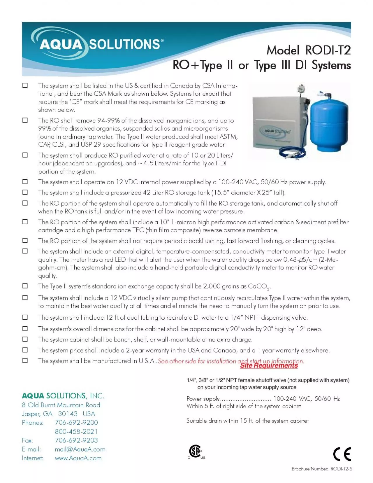
tional and bear the CSA Mark as shown below Systems for export t ID: 841665

water system type cabinet system water cabinet type valve fitting mounting power inlet tubing wall install purified drain supplied

Share:

Link:

Embed:

Download Presentation from below link

Download Pdf The PPT/PDF document "Brochure Number RODIT2S" is the property of its rightful owner. Permission is granted to download and print the materials on this web site for personal, non-commercial use only, and to display it on your personal computer provided you do not modify the materials and that you retain all copyright notices contained in the materials. By downloading content from our website, you accept the terms of this agreement.


Presentation Transcript

1 Brochure Number: RODI-T2-S AQUA UTIONS,
Brochure Number: RODI-T2-S AQUA UTIONS, INC.8 Old Burnt Mountain RoadJasper, GA 30143 USAPhones:706-692-9200Fax:706-692-9203E-mail:mail@AquaA.comwww.AquaA.com tional, and bear the CSA Mark as shown below. Systems for export thatshown below.found in ordinary tap water. The Type II water produced shall meet ASTM,CAP, CLSI, and USP 29 specifications for Type II reagent grade water.hour (dependent on upgrades), and ~4-5 Liters/min for the Type II DIThe system shall operate on 12 VDC internal power supplied by a 100-240 VAC, 50/60 Hz power supply.The system shall include a pressurized 42 Liter RO storage tank (15.5” diameter X 25” tall).The system shall include an external digital, temperature-compensated, conductivity meter to monitor Type II waterquality. The meter has a red LED that will alert the user when the water quality drops below 0.48-µS/cm (2-Me-quality.The Type II system’s standard ion exchange capacity shall be 2,000 grains as CaCOThe system shall include a 12 VDC virtually silent pump that continuously recirculates Type II water within the system,The system cabinet shall be bench, shelf, or wall-mountable at no extra charge.The system shall be manufactured in U.S.A.. See other side for installation and start-up information. Site Requirements Power supply.............................100-240 VAC, 50/60 HzSuitable drain within 15 ft. of the system cabinetype III DI Systemsype III DI Systemsype III DI Systems Water Front ViewSOLUTIONS, Inc. Basic Installation Instructions - Please follow the detailed instructions in the operating manual As shipped, AQUA Compact Combination Reverse Osmosis plus Type II DI (RO+DI) Water Purification Systems can bebench, shelf or wall-mounted at no extra charge. While bench mounting affords more flexibility, shelf or wall mounting can get and out of the way, conserving bench space for other uses. Regardless of the initial mounting method, it can be changed at any time. LEFTSIDE of the system, plus a grounded 100-240 VAC, 50/60 Hz electrical outlet within 5’ of the right side of the system. Electriction is less than 3 amps total. The system also requires a drain or sink within 15’ of the system.Note that the operating weight of the system can approach 100 pounds. If shelf-mounting, make sure the shelf can support this weight. Ifwall-mounting, make sure the wall can support this weight. In the case of wallboard attached to metal studs, attach a piece of 3/4” plywooddirectly to the studs first, and attach the system to the plywood. When wall-mounting, use 4 “industrial strength” 1/4” lag bolts, 1/4 “ toggleincluded in the Operating Manual supplied with the system. The system cabinet measures approximately 20” wide by 20” tall

2 by 12” deep.The storage tank is external
by 12” deep.The storage tank is external to the cabinet. After mounting the system cabinet, proceed as follows:a.Use an existing, or install a new, 1/4", 3/8" or 1/2" NPT female shutoff valve (not supplied with system) on your incoming tap water If a 1/2" valve is used, you will have to reduce the valve outlet end down from 1/2" NPT female to either 1/4" or 3/8"NPT female. b.Open the valve fully and run water out of it at full force until it runs clear. This is particularly important on new construction, where thec.Install a 1/4" (Part Number: T-MC-4-4) or 3/8" (Part Number: T-MC-4-6) NPT male by 1/4" Jaco type tube fitting (both are supplied withsystem) on your valved water source, using Teflon tape on the threads. (20' supplied with system - cut to required length) inlet fitting marked “Water Inlet”, located on bottom left side of system cabinet, using a push-in elbow connector, to the Jaco or Fitting # 1 is for 3/8” OD blue purified water tubing that transports RO purified water to and from the RO portion of the system and the RO storage tank. Thus, RO purified water travels in both directions through this tubing. Fitting # 2 is for the 3/8” purified water outlet line. Fitting # 3 is for the 1/4" purified water return line. Fitting # 4 is for 1/4” OD red RO tubing to drain from the RO storage tank. Fitting # 5 is for 1/4” OD red RO reject water tubing to drain.f.Install the conductivity sensor tee, dispenser valve tubing, drain lines, and the RO tank line on the right side of the cabing.Open cabinet door and make sure water inlet valve (located on black water inlet tubing on left bottom inside the cabinet) is ALL pressure gauges on the system read zero. Note that the valve is closed when the handle is perpendicular to the direction of flow,h.Install the ten inch activated carbon prefilter cartridge in the clear filter bowl, making sure the black gaskets are in place. Attach thefilter bowl to the housing located inside the system cabinet, making sure the O-ring on the bowl is in place, and hand-tighten firmly.i.Install the DI module in the system at this time. Note that the RO Cartridges arej.Plug the AC power cord into the power supply, but don’t plug it into the AC electricaloutlet at this time. Plug the black 2-wire 12 VDC power cord that comes from thepower supply into one of the shiny metal 12 VDC inlet connectors on the lower rightremaining connector.k.Inspect work done, making sure that system water inlet valve is CLOSED and thesystem's ELECTRICAL CORDS ARE NOT PLUGGED IN.Follow detailed installa-tion and start-up instructions in the Operating Manual.m.Call AQUA at 706-692-9200 or 800-458-2021 with any technica