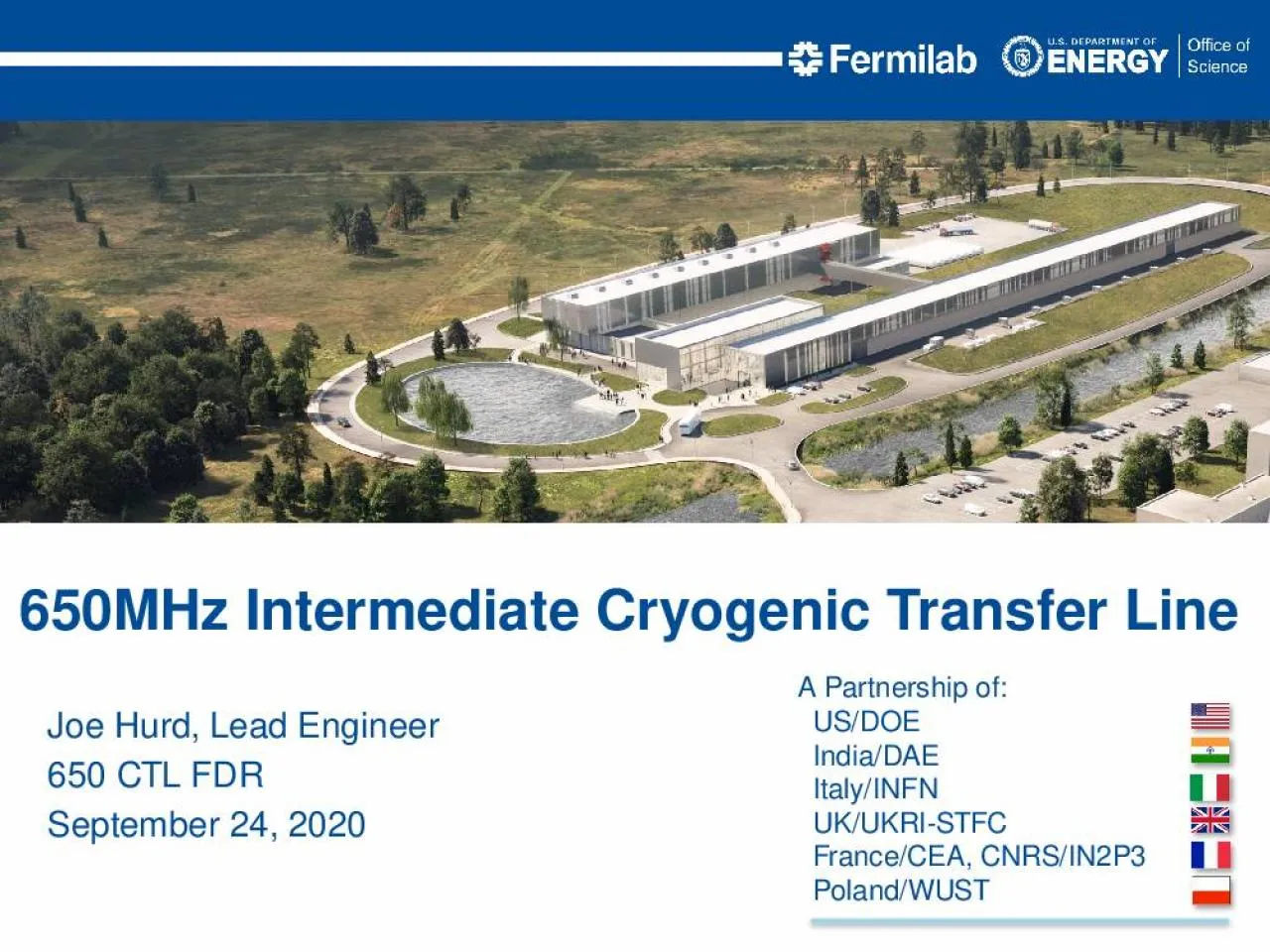
September 24 2020 650MHz Intermediate Cryogenic Transfer Line J Hurd PIP2IT 650 CTL FDR 2 The PIP2IT 650 Test Stand requires connecting the existing PIP2IT cryo transfer line to the 650 MHz cryomodules for testing ID: 911953
Download Presentation The PPT/PDF document "Joe Hurd, Lead Engineer 650 CTL FDR" is the property of its rightful owner. Permission is granted to download and print the materials on this web site for personal, non-commercial use only, and to display it on your personal computer provided you do not modify the materials and that you retain all copyright notices contained in the materials. By downloading content from our website, you accept the terms of this agreement.
Slide1
Joe Hurd, Lead Engineer650 CTL FDRSeptember 24, 2020
650MHz Intermediate Cryogenic Transfer Line
Slide2J. Hurd / PIP2IT 650 CTL FDR
2
The PIP2IT 650 Test Stand requires connecting the existing PIP2IT cryo transfer line to the 650 MHz cryomodules for testing
Interface of 650 MHz cryomodules does not match HWR
Requires an intermediate transfer line to jumper:5K Return40K Supply80K ReturnRemaining lines will not require jumper:5K supply2K pumping An Intermediate Cryo Transfer Line (650 CTL) was designed to serve this purposeThe 650 CTL will also allow for controlled warm-up/cool-down of the 40K shield of the 650 MHz cryomodules
Purpose
Sept 24, 2020
Slide3The HB650 cryomodule 40K shield has a cooldown constraint of 20K/hrThe existing PIP2IT Transfer Line does not have controlled warm-up/cool-down capabilities at the North end of the transfer line (the location where the 650 Test Stand will be located)
300K Warm Helium injection port was added to the 650 CTL design
½” ANSI flange will be connected to the warm helium header with control valve supported on the cave wall, similar to SSR1.
Temperature control input will be based on temperature sensors within the HB650
Design Change since PDRSept 24, 2020J. Hurd / PIP2IT 650 CTL FDR
3
Slide4Add vacuum parallel plate by the FDR. Make sure location good for u-tube pulls. Make sure stands and platform do not interfere.
Finish preliminary helium relief requirements by the FDR. Apply this to size the relieve valves.
Develop preliminary design for CTL supports and platforms necessary for U-tube installation/ removal by the FDR.
Develop preliminary procedure for isolation, depressurization, and U-tube installation/removal by the FDR. Verify that technicians have sufficient access to perform all steps in the procedure.
Check tolerance specifications and investigate U-tube design to ensure that a common U-tube set can be used for all cryomodules by the FDR.
Consider a means to ensure that a flex hose is not overstressed should a spider hang up by the FDR.
Consider lowering the elevation of the horizontal section of the CTL toward the floor to help simplify the CTL stand and to allow a platform over it to make U-tube access easier by the FDR.
PDR Review/Recommendations
J. Hurd / PIP2IT 650 CTL FDR
4
Sept 24, 2020
Slide5Flow Schematic
J. Hurd / PIP2IT 650 CTL FDR
5
PIP2IT transfer line
HB650MHz Cryomodule
Sept 24, 2020
Red: 40K Supply. MV-614-H
Orange: 80K Return- MV-616-H
Blue: 5K Supply- MV610-H
Green: 5K Return- MV-612-H
Purple: Warm Helium injection
Slide6J. Hurd / PIP2IT 650 CTL FDR
6
PID
Small snip from the overall PID (
F10042546 - Indico site SDP doc#13) will be updated in Teamcenter closer to installation
HB650 CM will be added to this PID once design is known
Orange 40 K Supply
Gold- 80 K Return
Dark Green- 5K Supply
Light Green- 5K Return
Pink- 2K Return
“B” in circle – indicates warm He injection
Sept 24, 2020
Slide73D model - in place in PIP2IT
J. Hurd / PIP2IT 650 CTL FDR
7
Sept 24, 2020
More views available on Indico in 3D Models-CTL Folder
Slide83D model
J. Hurd / PIP2IT 650 CTL FDR
8
80K return
40K Supply
5K Return
40K Supply
80K Return
5K Return
Sept 24, 2020
Warm Helium Injection
Slide9Relief and Bleed Valves + Brace
J. Hurd / PIP2IT 650 CTL FDR
9
Sept 24, 2020
Slide10Overview Drawing
J. Hurd / PIP2IT 650 CTL FDR
10
Sept 24, 2020
Full version (F10126703) located on Indico – CTL Drawings folder(several sub-component drawings also included)
Slide11J. Hurd / PIP2IT 650 CTL FDR
11
Internal Drawing piping
Sept 24, 2020
Full version (F10136778) located on Indico – CTL Drawings folder
Slide12Spider-G10
J. Hurd / PIP2IT 650 CTL FDR
12
Sept 24, 2020
Full version (F10126720) located on Indico – CTL Drawings folder
Slide13Support Stands
J. Hurd / PIP2IT 650 CTL FDR
13
Sept 24, 2020
Multiple views located on Indico – 3D Models-CTL support stand folder
Slide14Work Platform
J. Hurd / PIP2IT 650 CTL FDR
14
Sept 24, 2020
Multiple views located on Indico – 3D Model-Work Platform folder
Horizontal CTL lowered
Work Platform added over CTL
Comfortable working height
Protects CTL and parallel plate relief
~ 30”
~ 30”
~ 50”
(Person shown is 6’ 2”)
Slide15Work Platform
J. Hurd / PIP2IT 650 CTL FDR
15
Sept 24, 2020
Multiple views located on Indico – 3D Model-Work Platform folder
Provides safe access behind CM
Made out of 80/20
Modular design similar to other PIP2IT platforms (see next slide)
Slide16Work Platform – example drawings
J. Hurd / PIP2IT 650 CTL FDR
16
Sept 24, 2020
Multiple views located on Indico – False Floor and U-tube example folder
Example dwgs/models of existing PIP2IT HWR aisle platform
Made out of 80/20
Modular design
Slide17Thermal Flexibility
J. Hurd / PIP2IT 650 CTL FDR
17
Change from PDR: changed use of Dynamic Bending Radius to Static Bending Radius. Leads to 80K Return to use 5.5” live length on flex hose.
Preload of 1/8” implemented in calculation, except for WU/CD supply which is assumed no preload
Sept 24, 2020
Indico – SDP doc#15
Line
Length
Contraction
Static Min bend radius Radius
Required Live length with preload
Required Live Length for full pipe
Current live length
FOS with preload
FOS for full length
in
in
in
in
in
5K return
57.13
0.17
1.70
1.26
2.72
5.50
4.38
2.02
80K return
93.50
0.28
2.10
2.56
4.28
5.50
2.15
1.29
40K Supply
54.50
0.16
2.10
1.27
2.91
5.50
4.33
1.89
Wu/CD
27.25
0.04
1.20
---
0.99
4.00
---
4.04
Slide18Generant CRV-500B-K-275-psi (1/4") pressure relief valves will be installed on each manual isolation valve for trapped volume relief
Relief calculated based on CGA S1.3-2008
Reliefs based on one (1) relief valve when there are two (2) installed
J. Hurd / PIP2IT 650 CTL FDR
18
Pressure Relief- Cryogenic Process Pipe
Line
Qa
Factor of Safety
ft3/min_Air
5K RETURN
5.85
11.80
40K SUPPLY
6.14
11.25
80K RETURN
5.91
11.70
Installed Relief Capacity
K_d
0.67
-
coefficient of discharge
W_a
923.63
lb/hr
69.09
scfmAir
C
356
-
M
28.97
mol. Wt
T
520
R
when W_a is the rated capacity
A
0.05
in2
d_orifice
0.25
in
Sept 24, 2020
Indico – SDP doc#14
Slide19Pressure Relief - Vacuum
J. Hurd / PIP2IT 650 CTL FDR
19
The vacuum jacket relief capability was analyzed using CGA1.3-2008 requirements.
Per the CGA guidelines, the CVI can not relieve the transfer line adequately. 2 ½” parallel plate installed
Cross section
Water capacity
Volume
Water density multiplier
water capacity
require cross section area
Factor of Safety
in2
in2/lb
ft3
lb/ft3
lbs
in2
4.91
0.00024
3.77
62.40
235.32
0.06
86.92
Sept 24, 2020
Indico – SDP doc#14
Slide20Engineering Risk Analysis
Sept 24, 2020
J. Hurd / PIP2IT 650 CTL FDR
20
Indico – SDP doc#20
Slide21J. Hurd / PIP2IT 650 CTL FDR
21
Prevention through Design
Sept 24, 2020
Indico – SDP doc#07
Slide22ProcurementSimple designNot many long lead items to procureSafety
650 CTL will be located between the PIP2IT Transfer line and the 650MHz Cryomodule
Space will be tight for personnel to sting and unsting u-tubes. Safety measures must be considered
ODH - Proper LOTO procedureTight Space - proper footing and work platforms, clear accessibility, use of crane (similar to current HWR and SSR1 procedures)
Prevention through DesignJ. Hurd / PIP2IT 650 CTL FDR22
Sept 24, 2020
Slide23Failure Mode and Effect analysis shows the simplicity of the design (see
Indico-SDP doc#06
for full FMEA)
A manual valve fails closed, it prevents the U-tube from being stung into the 650 CTLA manual valve fails open, can lead to an ODH event
A safety valve fails closed, there is a redundant safety valve on the line and upstream if the system is stung inA safety valve fails open, leads to an ODH eventThe cave remains safe in both the “failed open” scenarios, as this is accounted for in the ODH analysisAdditionally, alarms and measures are in place to warn personnel of the danger: Personal O2 monitor, O2 monitors mounted on wall with sirens and strobesFMEA
J. Hurd / PIP2IT 650 CTL FDR
23
Sept 24, 2020
Slide24U-tubes will be modeled in the overall 3D to ensure no unnecessary overlap with other u-tubes or existing piping
Once 650 CTL is installed and HB650 CM is in place, Alignment personnel takes measurements for the final fabrication drawing
End pieces will be fabricated ahead of time
Lengths entered in model and final drawings generated
U-tubes fabricated and pressure testedPiping note written ahead of time if possibleU-tubes installedU-tubesJ. Hurd / PIP2IT 650 CTL FDR
24
Sept 24, 2020
Slide25No bayonet tolerances have been specified for the HB650 Cryomodule design at this timeThis effort is being worked on by Andrew Dalesandro of the PIP-II Technical Integration team
Necessary to determine for U-tube reusability within PIP2IT for testing of multiple HB650 cryomodules
LB650 interfaces have not yet been designed as of this presentation.
U-tubes with flexibility will be developed similar to HWR 80K return U-tube shown in next slide
Bayonet Tolerances J. Hurd / PIP2IT 650 CTL FDR25
Sept 24, 2020
Slide26HWR 80K Return - example F10132199
J. Hurd / PIP2IT 650 CTL FDR
26
Sept 24, 2020
Full version (F10132199) located on Indico – False Floor and U-tube example drawings folder
Slide27HWR 2K return - example F10117405
J. Hurd / PIP2IT 650 CTL FDR
27
Sept 24, 2020
Full version (F10117405) located on Indico – False Floor and U-tube example drawings folder
Slide28U-tube Insertion and Isolation Procedure ED0012574 based on HWR pump and backfill doc ED0011501Includes Pump and Backfill procedure for insertion phaseApplied Physics and Superconducting Technology Division Departmental Procedure (TDDP) will be developed for a standard LOTO procedure to be implemented when swapping cryomodules.
U-tube Insertion and Isolation Plan
J. Hurd / PIP2IT 650 CTL FDR
28
Sept 24, 2020
Indico – SDP doc#19
Slide29ODH Analysis
J. Hurd / PIP2IT 650 CTL FDR
29
Sept 24, 2020
Indico – SDP doc#08
Slide30The PIP2IT cave is currently classified as ODH 2Due to a low pressure component in HWR, the 2K bath must be vented into the cave leading to the ODH Class
Based on the assumption that the 650MHz Cryomodule 2K rupture disk will relieve outside the cave
ODH Class will change from ODH 2 to ODH 1
ODH Analysis
J. Hurd / PIP2IT 650 CTL FDR30
Total result
9.68E-06
ODH Class
1
Sept 24, 2020
Indico – SDP doc#08
Slide31Draft QC Plan on
Indico-SDP doc#17
, maintained in TC ED0011285
Being developed with PIP-II QC groupJoe Hurd worked with Tom Digrazia
Reviewed draft, compared with PIPII standards for QCQC draft updated to PIPII standards, ready for final reviewGoals of the QC documentList Code and Standards for this Intermediate Transfer lineList Inspections and tests to be completed Lay out common fabrication practices and guidelines to be followedQuality Control
J. Hurd / PIP2IT 650 CTL FDR
31
Sept 24, 2020
Slide32Draft Schedule
J. Hurd / PIP2IT 650 CTL FDR
32
650 Test Stand P6 Baseline Schedule
Procurement/Fabrication – 5 months
Installation –
5 months
Ready for 1
st
CM installation in Aug.
(CM now delayed until Oct. or Dec?)
650 CTL schedule fits well within the baseline schedule
Completion (System ready for cooldown – end of July)
Push out of CM delivery adds additional cushion to CTL schedule
Sept 24, 2020
Full P6 schedule for 650 Test Stand on Indico – SDP doc#09
Slide33Validation Plan is a combination of Detailed procurement/fab./install. schedule –
SDP doc#18
see next slides
QC Plan – SDP doc#17
U-tube insertion procedure - SDP doc#19Draft CTL Piping Note – SDP doc#16Validation Plan/ScheduleSept 24, 2020
J. Hurd / PIP2IT 650 CTL FDR
33
Slide34Detailed CTL Schedule – Page 1
Sept 24, 2020
J. Hurd / PIP2IT 650 CTL FDR
34
Slide35Detailed CTL Schedule – Page 2
Sept 24, 2020
J. Hurd / PIP2IT 650 CTL FDR
35
Slide36From the PDR, the following was addressedOptimize/finalize location of 650 CTL (vertical and horizontal) to maximize accessibility
Design support stand for 650 CTL
Complete relief calculations for Cryogenic process piping
Parallel plate relief for transfer lineFinalize u-tube designUpdate all calculations, models, and drawings to a final state
Finalize QC PlanNext StepsJ. Hurd / PIP2IT 650 CTL FDR36
Sept 24, 2020
Slide37J. Hurd / PIP2IT 650 CTL FDR
37
The 650 CTL design has progressed well
The design is simple and straight forward
We believe the design and documentation are now at a final stage, and that all recommendations from the PDR have been addressedWe feel we are ready to move into the procurement/fabrication phase of the 650 Intermediate Cryogenic Transfer LineThank You!Summary
Sept 24, 2020