
1-1 CIS 5617, Spring2019 Anduo Wang Based on



Description: 1-1 CIS 5617, Spring2019 Anduo Wang Based on Slides created by JFKKWR 7th edition Jim Kurose, Keith Ross PearsonAddison Wesley April 2016 Lecture 12 Chapter 6 Link Layer and LANs Chapter 6: Link layer and LANs our goals: understand
Related Topics
Download Presentation
"1-1 CIS 5617, Spring2019 Anduo Wang Based on" is the property of its rightful owner. Permission is granted to download and print the materials on this website for personal, non-commercial use only, and to display it on your personal computer provided you do not modify the materials and that you retain all copyright notices contained in the materials. By downloading content from our website, you accept the terms of this agreement.
Presentation Transcript
slide1. 1-1 CIS 5617, Spring2019
Anduo Wang
Based on Slides created by JFK/KWR 7th edition Jim Kurose, Keith Ross Pearson/Addison Wesley April 2016 Lecture 12 – Chapter 6
Link Layer and LANs<br>
slide2. Chapter 6: Link layer and LANs our goals:
understand principles behind link layer services:
error detection, correction
sharing a broadcast channel: multiple access
link layer addressing
local area networks: Ethernet, VLANs
instantiation, implementation of various link layer technologies 6-2 Link Layer and LANs<br>
slide3. Link layer, LANs: outline 6.1 introduction, services
6.2 error detection, correction
6.3 multiple access protocols
6.4 LANs
addressing, ARP
Ethernet
switches
VLANS 6.5 link virtualization: MPLS 6-3 Link Layer and LANs<br>
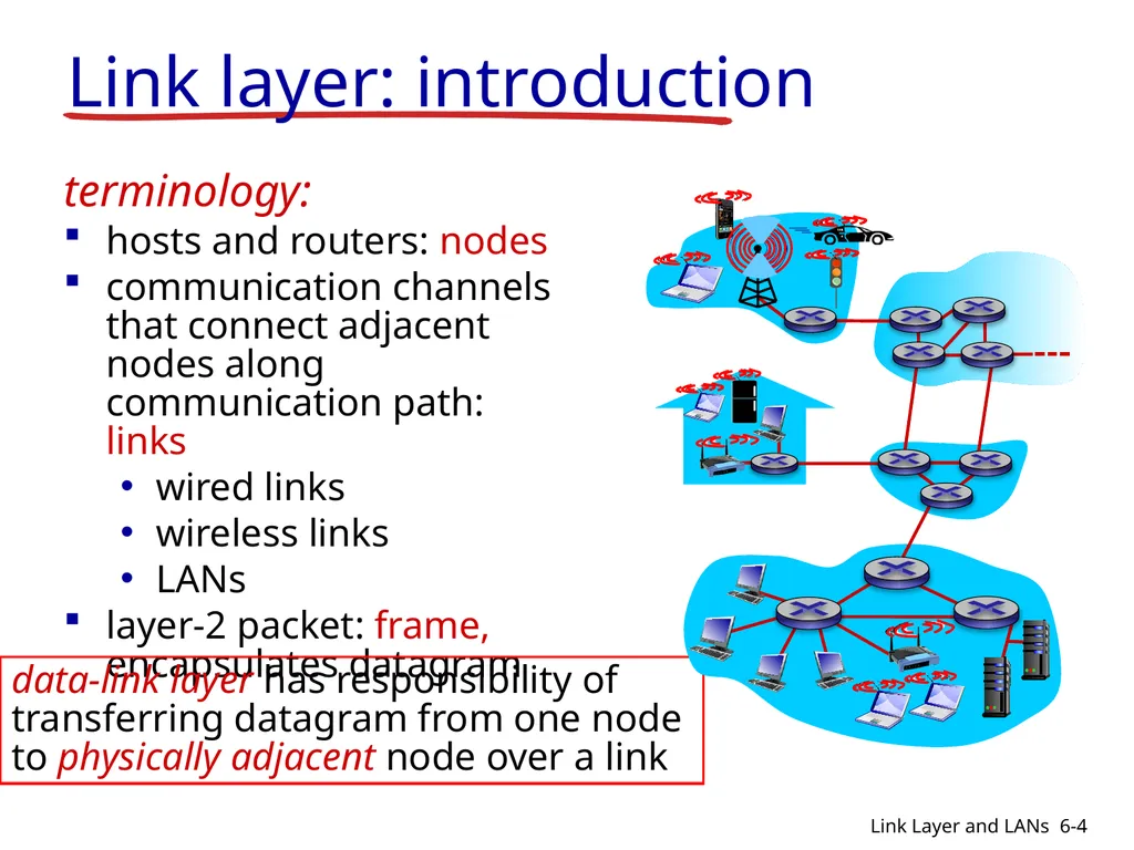
slide4. Link layer: introduction terminology:
hosts and routers: nodes
communication channels that connect adjacent nodes along communication path: links
wired links
wireless links
LANs
layer-2 packet: frame, encapsulates datagram data-link layer has responsibility of
transferring datagram from one node
to physically adjacent node over a link 6-4 Link Layer and LANs<br>
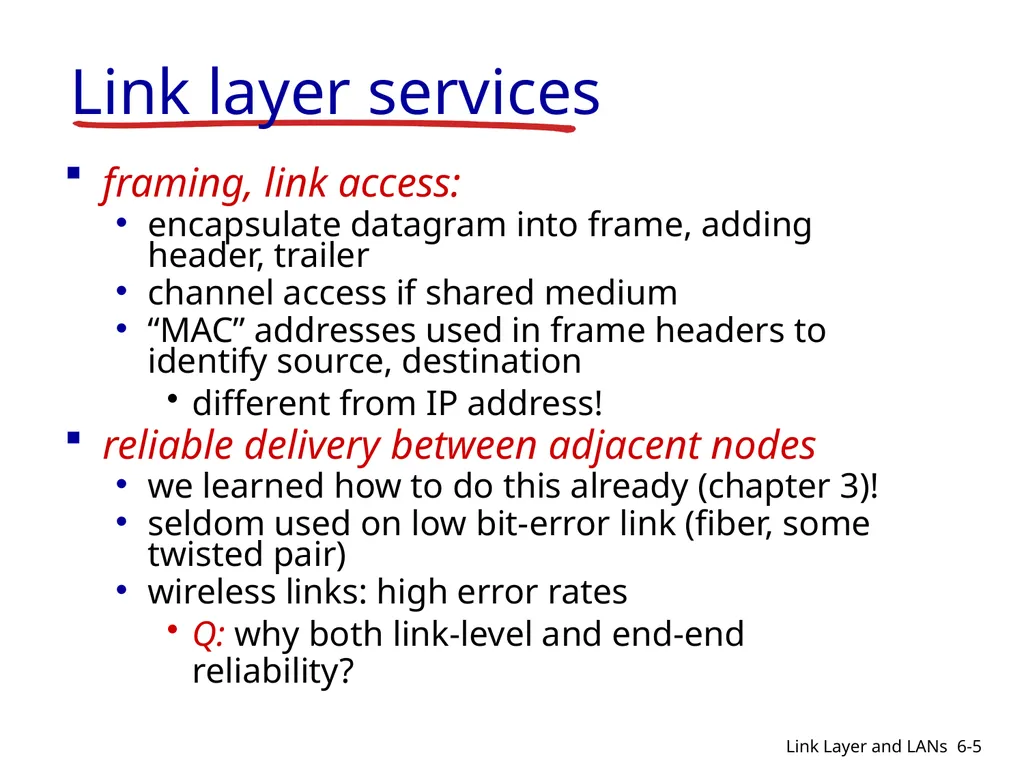
slide5. Link layer services framing, link access:
encapsulate datagram into frame, adding header, trailer
channel access if shared medium
“MAC” addresses used in frame headers to identify source, destination
different from IP address!
reliable delivery between adjacent nodes
we learned how to do this already (chapter 3)!
seldom used on low bit-error link (fiber, some twisted pair)
wireless links: high error rates
Q: why both link-level and end-end reliability? 6-5 Link Layer and LANs<br>
slide6. flow control:
pacing between adjacent sending and receiving nodes
error detection:
errors caused by signal attenuation, noise.
receiver detects presence of errors:
signals sender for retransmission or drops frame
error correction:
receiver identifies and corrects bit error(s) without resorting to retransmission
half-duplex and full-duplex
with half duplex, nodes at both ends of link can transmit, but not at same time Link layer services (more) 6-6 Link Layer and LANs<br>
slide7. Link layer, LANs: outline 6.1 introduction, services
6.2 error detection, correction
6.3 multiple access protocols
6.4 LANs
addressing, ARP
Ethernet
switches
VLANS 6.5 link virtualization: MPLS
6.6 data center networking
6.7 a day in the life of a web request 6-7 Link Layer and LANs<br>
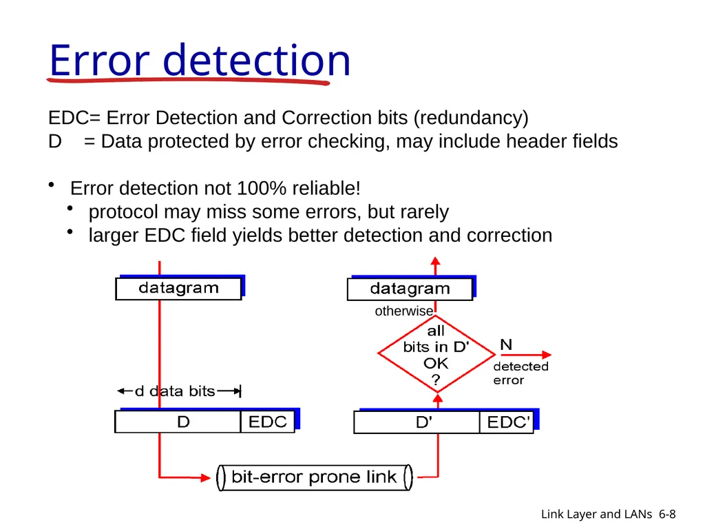
slide8. Error detection EDC= Error Detection and Correction bits (redundancy)
D = Data protected by error checking, may include header fields
Error detection not 100% reliable!
protocol may miss some errors, but rarely
larger EDC field yields better detection and correction otherwise 6-8 Link Layer and LANs<br>
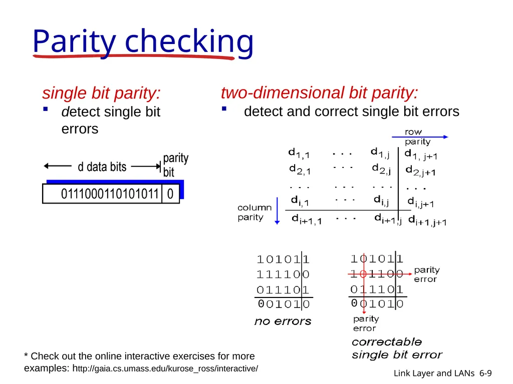
slide9. Parity checking single bit parity:
detect single bit errors two-dimensional bit parity:
detect and correct single bit errors 0 0 6-9 Link Layer and LANs * Check out the online interactive exercises for more examples: http://gaia.cs.umass.edu/kurose_ross/interactive/<br>
slide10. Link layer, LANs: outline 6.1 introduction, services
6.2 error detection, correction
6.3 multiple access protocols
6.4 LANs
addressing, ARP
Ethernet
switches
VLANS 6.5 link virtualization: MPLS 6-10 Link Layer and LANs<br>
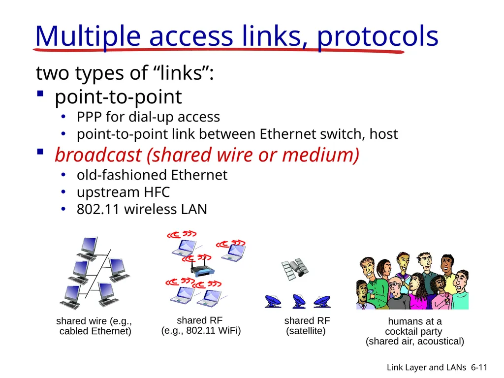
slide11. Multiple access links, protocols two types of “links”:
point-to-point
PPP for dial-up access
point-to-point link between Ethernet switch, host
broadcast (shared wire or medium)
old-fashioned Ethernet
upstream HFC
802.11 wireless LAN shared wire (e.g.,
cabled Ethernet) shared RF
(e.g., 802.11 WiFi) shared RF
(satellite) humans at a
cocktail party
(shared air, acoustical) 6-11 Link Layer and LANs<br>
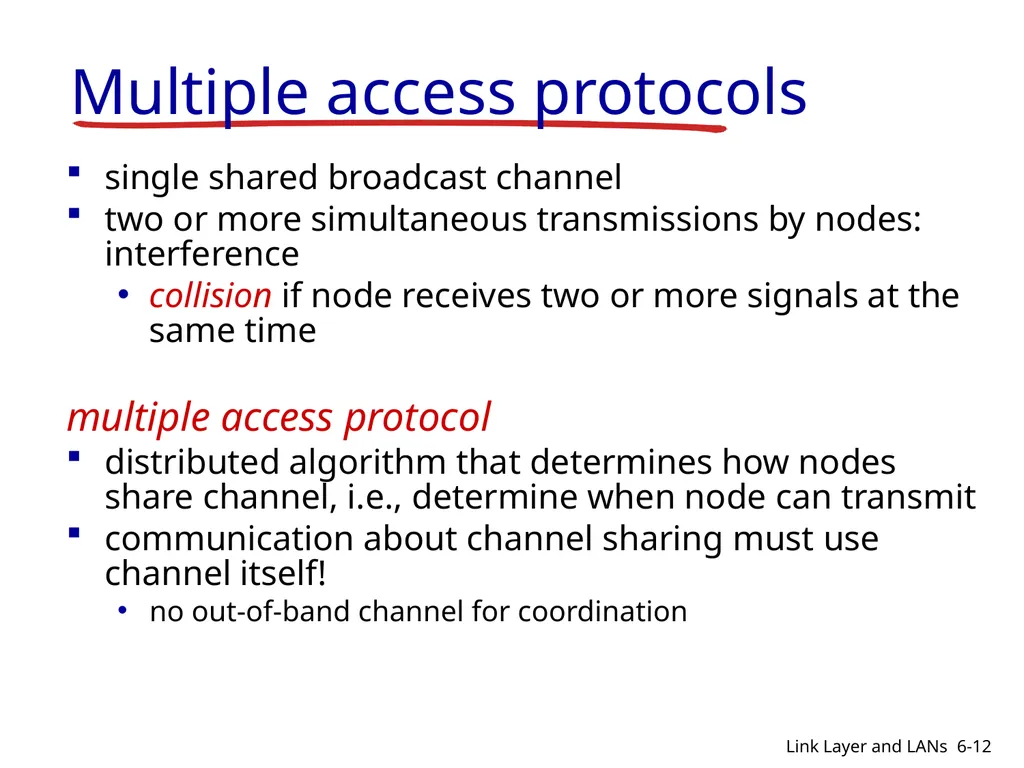
slide12. Multiple access protocols single shared broadcast channel
two or more simultaneous transmissions by nodes: interference
collision if node receives two or more signals at the same time
multiple access protocol
distributed algorithm that determines how nodes share channel, i.e., determine when node can transmit
communication about channel sharing must use channel itself!
no out-of-band channel for coordination 6-12 Link Layer and LANs<br>
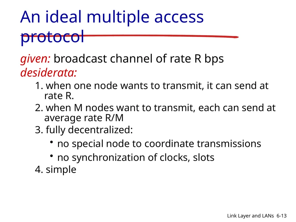
slide13. An ideal multiple access protocol given: broadcast channel of rate R bps
desiderata:
1. when one node wants to transmit, it can send at rate R.
2. when M nodes want to transmit, each can send at average rate R/M
3. fully decentralized:
no special node to coordinate transmissions
no synchronization of clocks, slots
4. simple 6-13 Link Layer and LANs<br>
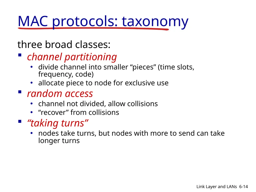
slide14. MAC protocols: taxonomy three broad classes:
channel partitioning
divide channel into smaller “pieces” (time slots, frequency, code)
allocate piece to node for exclusive use
random access
channel not divided, allow collisions
“recover” from collisions
“taking turns”
nodes take turns, but nodes with more to send can take longer turns 6-14 Link Layer and LANs<br>
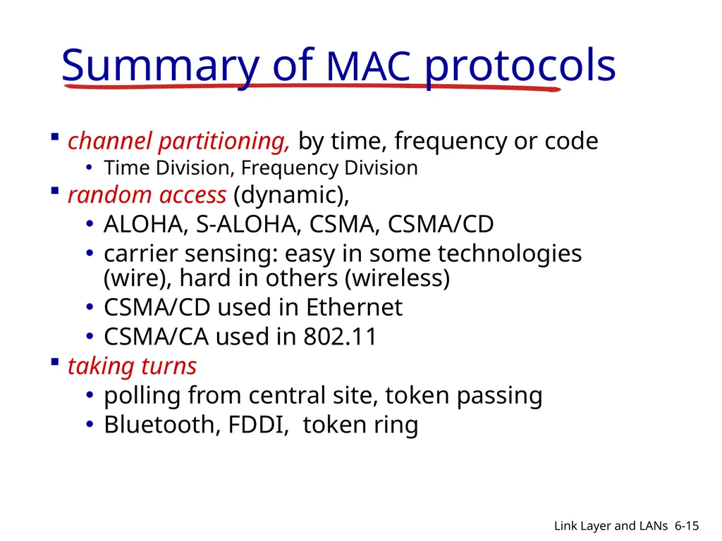
slide15. Summary of MAC protocols channel partitioning, by time, frequency or code
Time Division, Frequency Division
random access (dynamic),
ALOHA, S-ALOHA, CSMA, CSMA/CD
carrier sensing: easy in some technologies (wire), hard in others (wireless)
CSMA/CD used in Ethernet
CSMA/CA used in 802.11
taking turns
polling from central site, token passing
Bluetooth, FDDI, token ring 6-15 Link Layer and LANs<br>
slide16. Link layer, LANs: outline 6.1 introduction, services
6.2 error detection, correction
6.3 multiple access protocols
6.4 LANs
addressing, ARP
Ethernet
switches
VLANS 6.5 link virtualization: MPLS
6.6 data center networking
6.7 a day in the life of a web request 6-16 Link Layer and LANs<br>
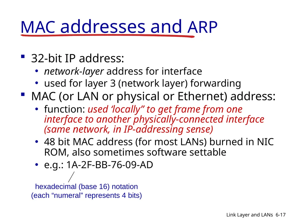
slide17. MAC addresses and ARP 32-bit IP address:
network-layer address for interface
used for layer 3 (network layer) forwarding
MAC (or LAN or physical or Ethernet) address:
function: used ‘locally” to get frame from one interface to another physically-connected interface (same network, in IP-addressing sense)
48 bit MAC address (for most LANs) burned in NIC ROM, also sometimes software settable
e.g.: 1A-2F-BB-76-09-AD hexadecimal (base 16) notation
(each “numeral” represents 4 bits) 6-17 Link Layer and LANs<br>
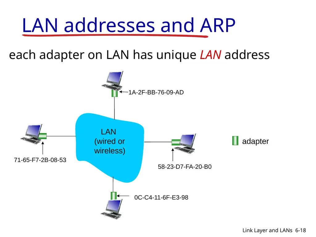
slide18. LAN addresses and ARP each adapter on LAN has unique LAN address adapter 1A-2F-BB-76-09-AD 58-23-D7-FA-20-B0 0C-C4-11-6F-E3-98 71-65-F7-2B-08-53 LAN
(wired or
wireless) 6-18 Link Layer and LANs<br>
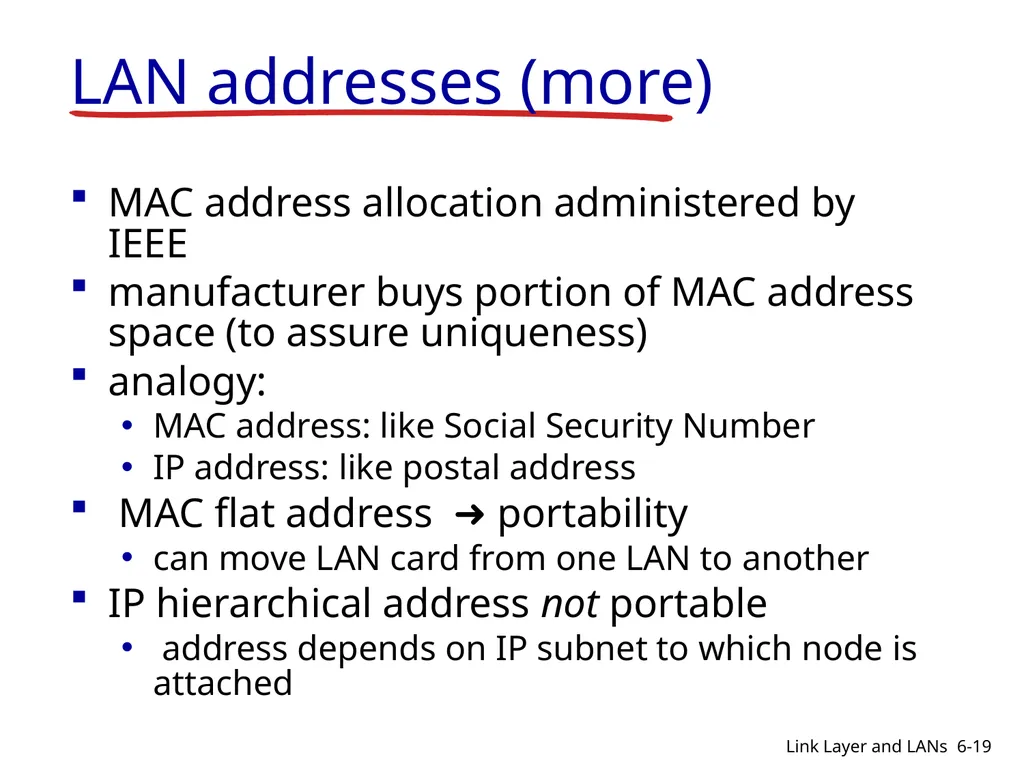
slide19. LAN addresses (more) MAC address allocation administered by IEEE
manufacturer buys portion of MAC address space (to assure uniqueness)
analogy:
MAC address: like Social Security Number
IP address: like postal address
MAC flat address ➜ portability
can move LAN card from one LAN to another
IP hierarchical address not portable
address depends on IP subnet to which node is attached 6-19 Link Layer and LANs<br>
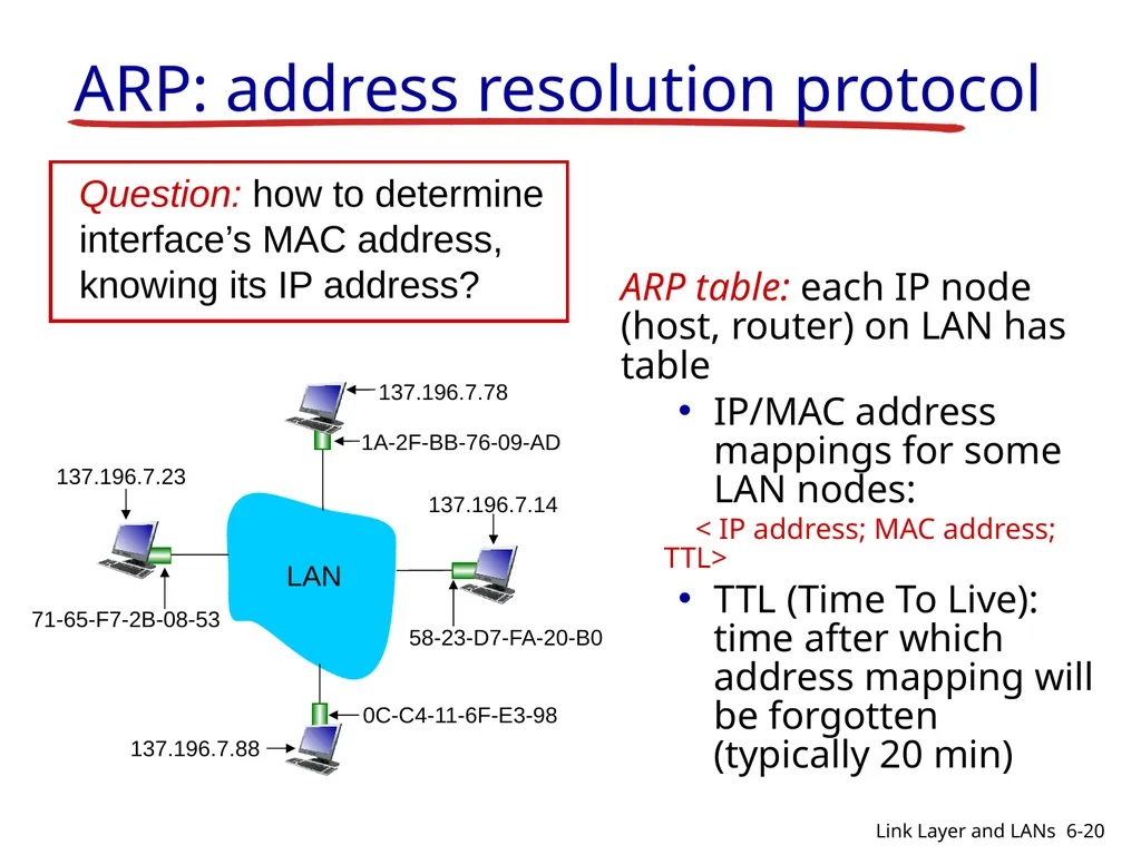
slide20. ARP: address resolution protocol ARP table: each IP node (host, router) on LAN has table
IP/MAC address mappings for some LAN nodes:
< IP address; MAC address; TTL>
TTL (Time To Live): time after which address mapping will be forgotten (typically 20 min) 1A-2F-BB-76-09-AD 58-23-D7-FA-20-B0 0C-C4-11-6F-E3-98 71-65-F7-2B-08-53 LAN 137.196.7.23 137.196.7.78 137.196.7.14 137.196.7.88 6-20 Link Layer and LANs<br>
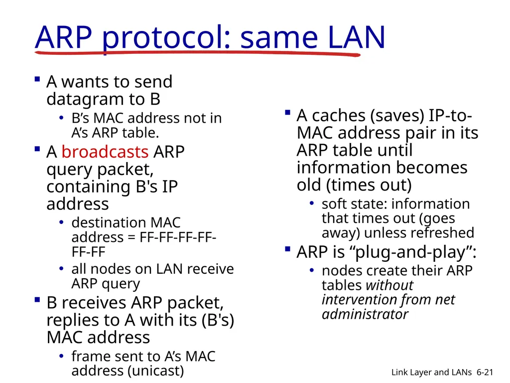
slide21. ARP protocol: same LAN A wants to send datagram to B
B’s MAC address not in A’s ARP table.
A broadcasts ARP query packet, containing B's IP address
destination MAC address = FF-FF-FF-FF-FF-FF
all nodes on LAN receive ARP query
B receives ARP packet, replies to A with its (B's) MAC address
frame sent to A’s MAC address (unicast) A caches (saves) IP-to-MAC address pair in its ARP table until information becomes old (times out)
soft state: information that times out (goes away) unless refreshed
ARP is “plug-and-play”:
nodes create their ARP tables without intervention from net administrator 6-21 Link Layer and LANs<br>
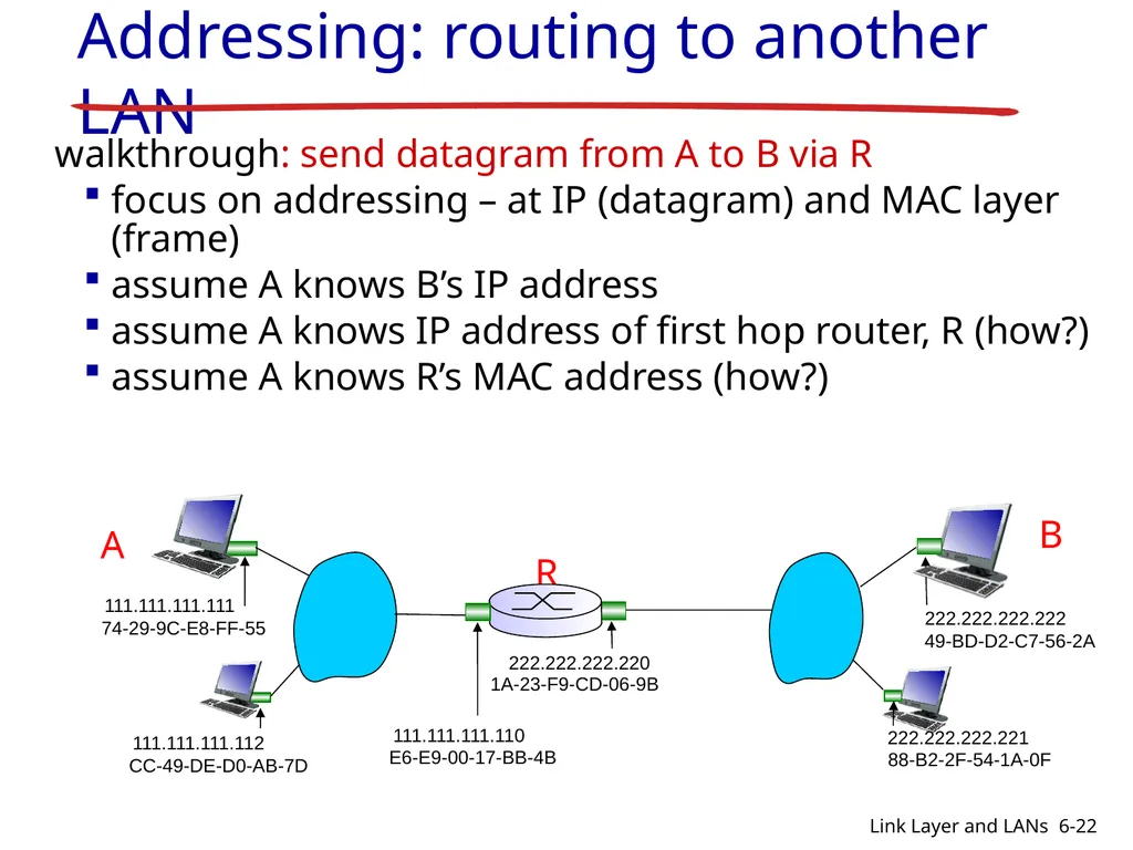
slide22. walkthrough: send datagram from A to B via R
focus on addressing – at IP (datagram) and MAC layer (frame)
assume A knows B’s IP address
assume A knows IP address of first hop router, R (how?)
assume A knows R’s MAC address (how?) Addressing: routing to another LAN 6-22 Link Layer and LANs<br>
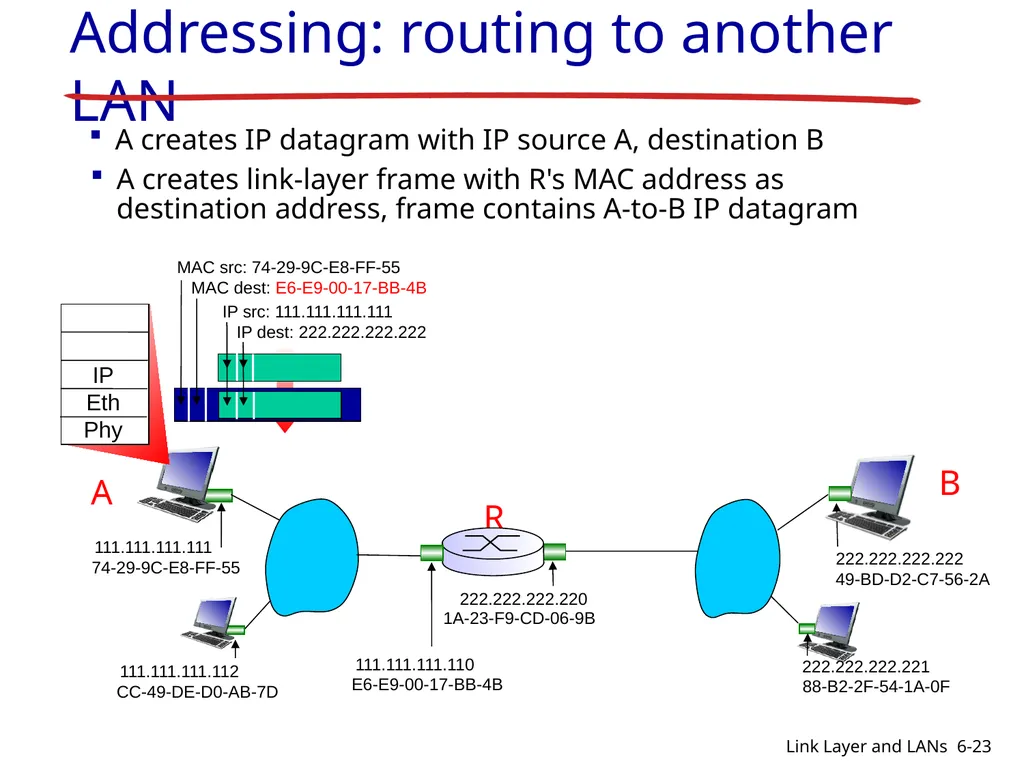
slide23. Addressing: routing to another LAN A creates IP datagram with IP source A, destination B A creates link-layer frame with R's MAC address as destination address, frame contains A-to-B IP datagram 6-23 Link Layer and LANs<br>
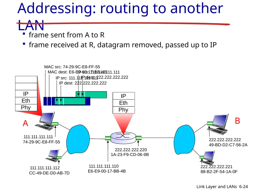
slide24. Addressing: routing to another LAN frame sent from A to R frame received at R, datagram removed, passed up to IP 6-24 Link Layer and LANs<br>
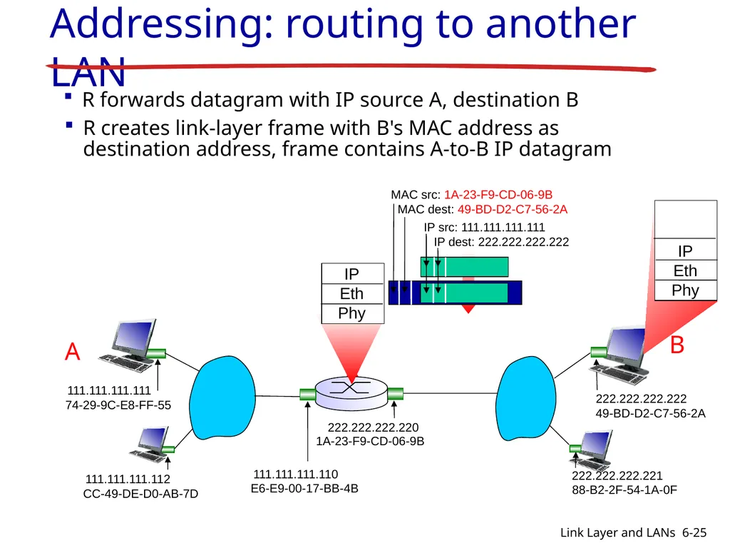
slide25. Addressing: routing to another LAN R forwards datagram with IP source A, destination B R creates link-layer frame with B's MAC address as destination address, frame contains A-to-B IP datagram 6-25 Link Layer and LANs<br>
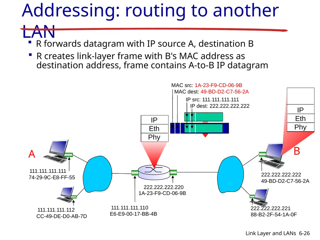
slide26. Addressing: routing to another LAN R forwards datagram with IP source A, destination B R creates link-layer frame with B's MAC address as destination address, frame contains A-to-B IP datagram 6-26 Link Layer and LANs<br>
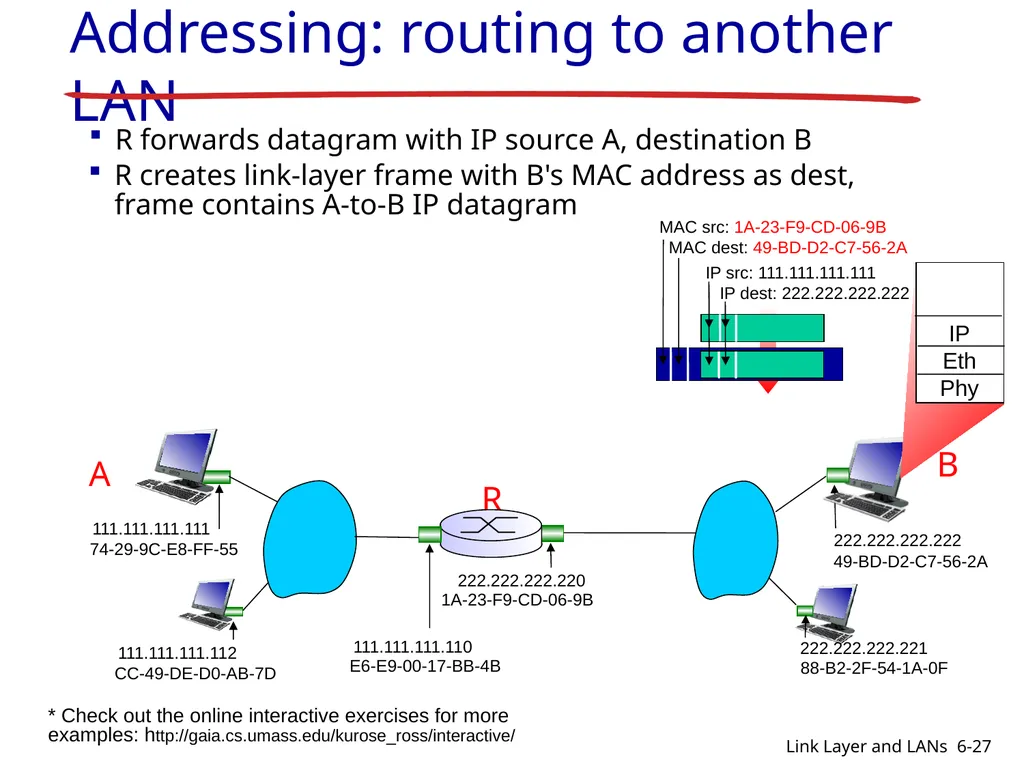
slide27. R 1A-23-F9-CD-06-9B 222.222.222.220 CC-49-DE-D0-AB-7D 111.111.111.112 111.111.111.111 74-29-9C-E8-FF-55 A 222.222.222.221 88-B2-2F-54-1A-0F B Addressing: routing to another LAN R forwards datagram with IP source A, destination B R creates link-layer frame with B's MAC address as dest, frame contains A-to-B IP datagram 6-27 Link Layer and LANs * Check out the online interactive exercises for more examples: http://gaia.cs.umass.edu/kurose_ross/interactive/<br>
slide28. Link layer, LANs: outline 6.1 introduction, services
6.2 error detection, correction
6.3 multiple access protocols
6.4 LANs
addressing, ARP
Ethernet
switches
VLANS 6.5 link virtualization: MPLS 6-28 Link Layer and LANs<br>
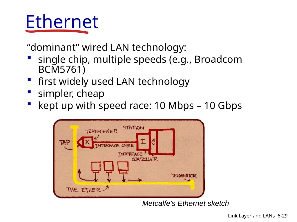
slide29. Ethernet “dominant” wired LAN technology:
single chip, multiple speeds (e.g., Broadcom BCM5761)
first widely used LAN technology
simpler, cheap
kept up with speed race: 10 Mbps – 10 Gbps Metcalfe’s Ethernet sketch 6-29 Link Layer and LANs<br>
slide30. Ethernet: physical topology bus: popular through mid 90s
all nodes in same collision domain (can collide with each other)
star: prevails today
active switch in center
each “spoke” runs a (separate) Ethernet protocol (nodes do not collide with each other) switch bus: coaxial cable star 6-30 Link Layer and LANs<br>
slide31. Ethernet: unreliable, connectionless connectionless: no handshaking between sending and receiving NICs
unreliable: receiving NIC doesn't send acks or nacks to sending NIC
data in dropped frames recovered only if initial sender uses higher layer rdt (e.g., TCP), otherwise dropped data lost
Ethernet’s MAC protocol: unslotted CSMA/CD with binary backoff 6-31 Link Layer and LANs<br>
slide32. Link layer, LANs: outline 6.1 introduction, services
6.2 error detection, correction
6.3 multiple access protocols
6.4 LANs
addressing, ARP
Ethernet
switches
VLANS 6.5 link virtualization: MPLS 6-32 Link Layer and LANs<br>
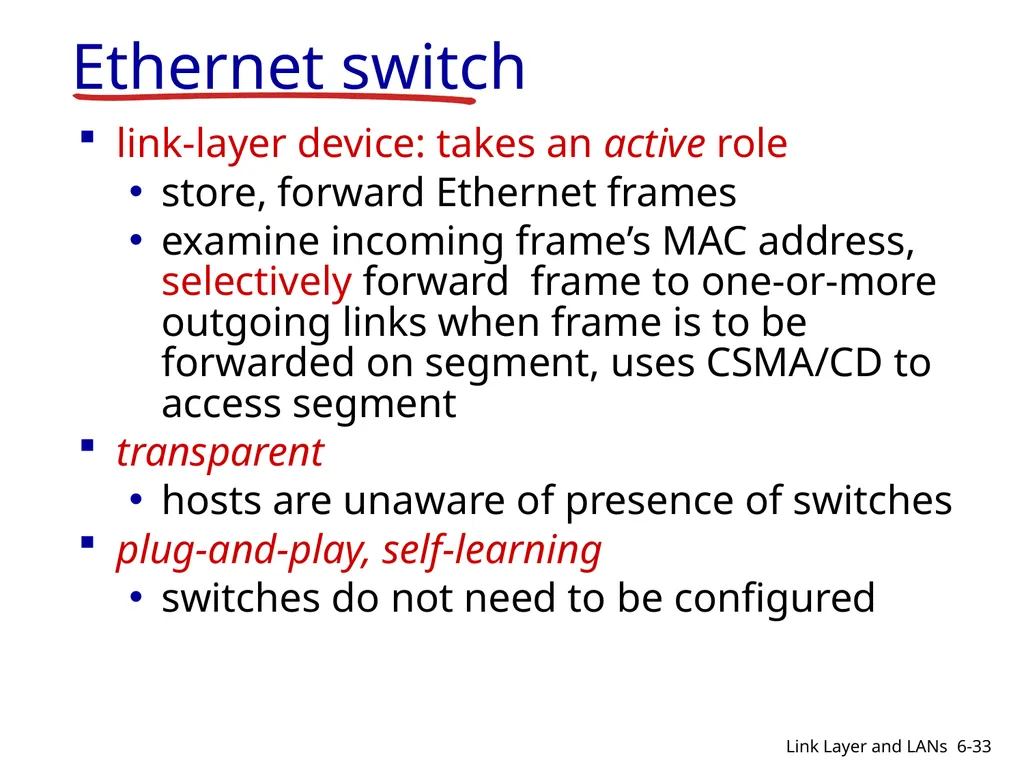
slide33. Ethernet switch link-layer device: takes an active role
store, forward Ethernet frames
examine incoming frame’s MAC address, selectively forward frame to one-or-more outgoing links when frame is to be forwarded on segment, uses CSMA/CD to access segment
transparent
hosts are unaware of presence of switches
plug-and-play, self-learning
switches do not need to be configured 6-33 Link Layer and LANs<br>
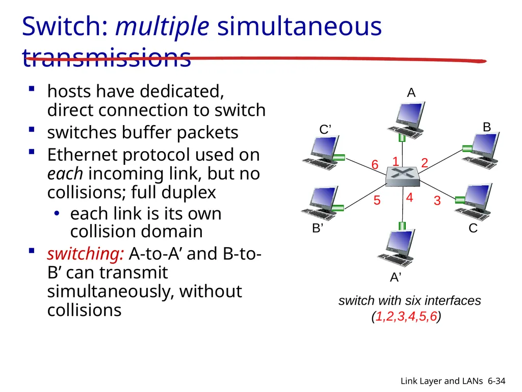
slide34. Switch: multiple simultaneous transmissions hosts have dedicated, direct connection to switch
switches buffer packets
Ethernet protocol used on each incoming link, but no collisions; full duplex
each link is its own collision domain
switching: A-to-A’ and B-to-B’ can transmit simultaneously, without collisions 6-34 Link Layer and LANs<br>
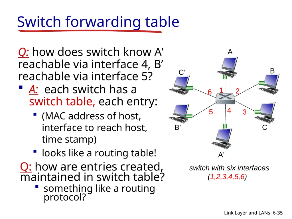
slide35. Switch forwarding table Q: how does switch know A’ reachable via interface 4, B’ reachable via interface 5? A: each switch has a switch table, each entry:
(MAC address of host, interface to reach host, time stamp)
looks like a routing table! Q: how are entries created, maintained in switch table?
something like a routing protocol? 6-35 Link Layer and LANs<br>
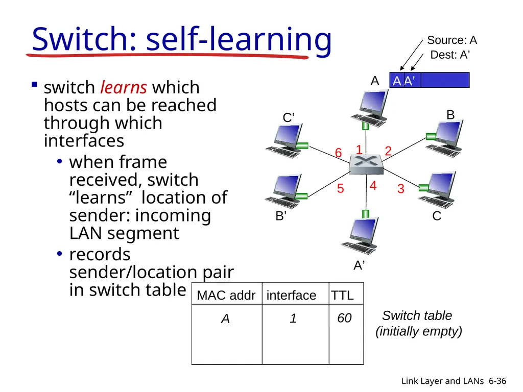
slide36. Switch: self-learning switch learns which hosts can be reached through which interfaces
when frame received, switch “learns” location of sender: incoming LAN segment
records sender/location pair in switch table Switch table
(initially empty) 6-36 Link Layer and LANs<br>
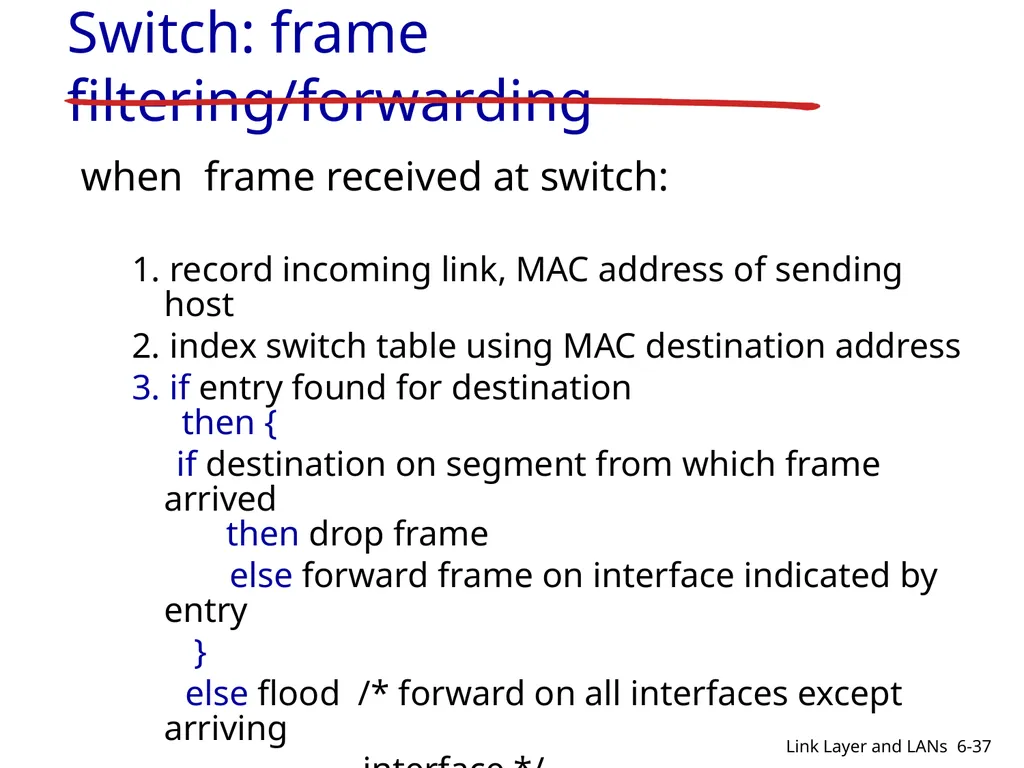
slide37. Switch: frame filtering/forwarding when frame received at switch:
1. record incoming link, MAC address of sending host
2. index switch table using MAC destination address
3. if entry found for destination then {
if destination on segment from which frame arrived then drop frame
else forward frame on interface indicated by entry
}
else flood /* forward on all interfaces except arriving
interface */ 6-37 Link Layer and LANs<br>
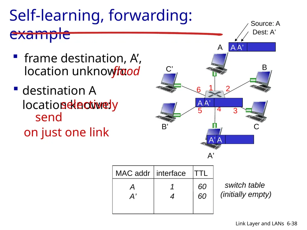
slide38. Self-learning, forwarding: example switch table
(initially empty) frame destination, A’, location unknown: flood destination A location known: selectively send
on just one link 6-38 Link Layer and LANs<br>
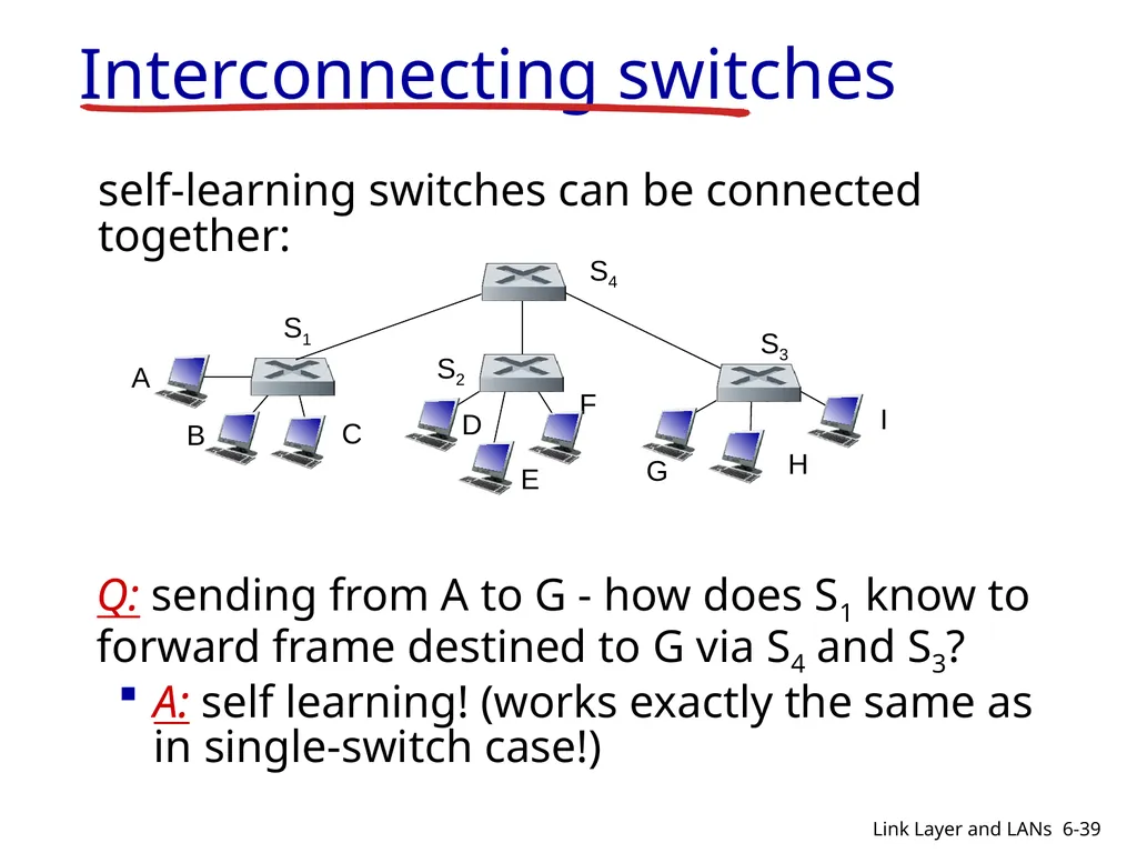
slide39. Interconnecting switches self-learning switches can be connected together: Q: sending from A to G - how does S1 know to forward frame destined to G via S4 and S3?
A: self learning! (works exactly the same as in single-switch case!) 6-39 Link Layer and LANs<br>
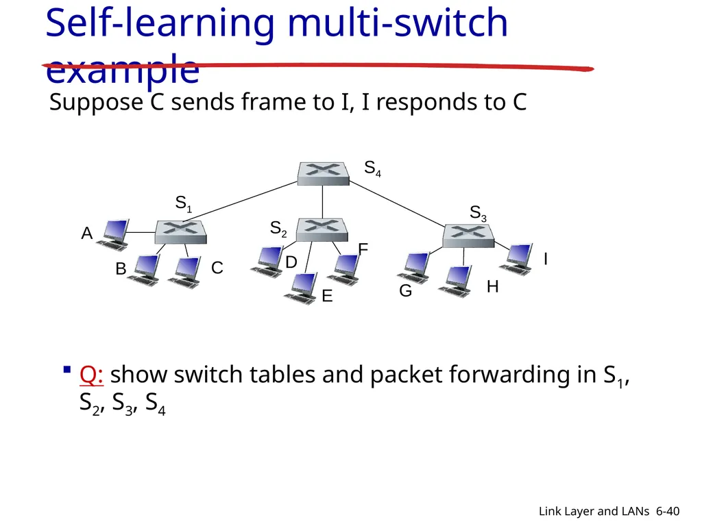
slide40. Self-learning multi-switch example Suppose C sends frame to I, I responds to C Q: show switch tables and packet forwarding in S1, S2, S3, S4 6-40 Link Layer and LANs<br>
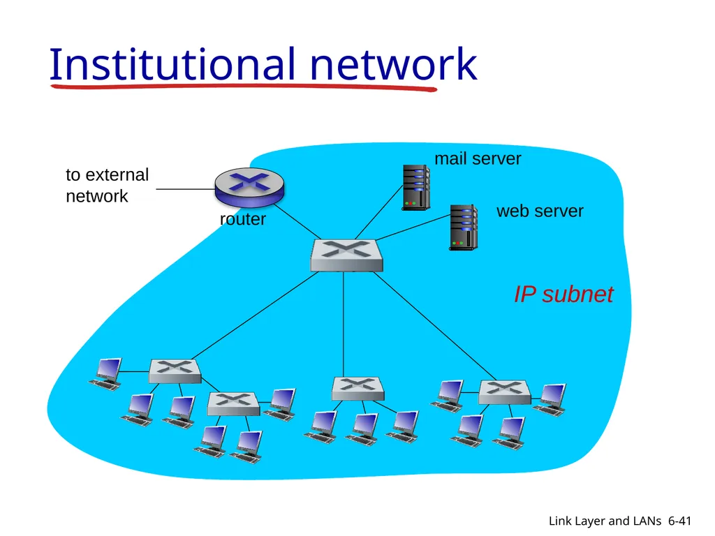
slide41. Institutional network to external
network router IP subnet mail server web server 6-41 Link Layer and LANs<br>
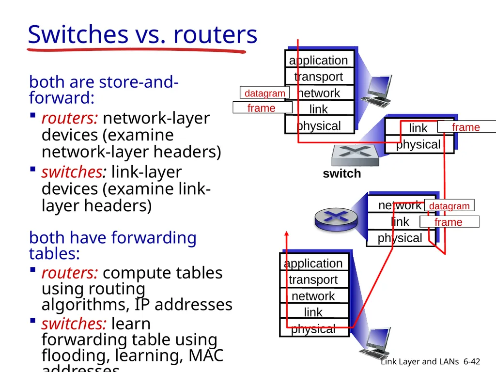
slide42. Switches vs. routers both are store-and-forward:
routers: network-layer devices (examine network-layer headers)
switches: link-layer devices (examine link-layer headers)
both have forwarding tables:
routers: compute tables using routing algorithms, IP addresses
switches: learn forwarding table using flooding, learning, MAC addresses application
transport
network
link
physical switch application
transport
network
link
physical 6-42 Link Layer and LANs<br>
slide43. Link layer, LANs: outline 6.1 introduction, services
6.2 error detection, correction
6.3 multiple access protocols
6.4 LANs
addressing, ARP
Ethernet
switches
VLANS 6.5 link virtualization: MPLS 6-43 Link Layer and LANs<br>
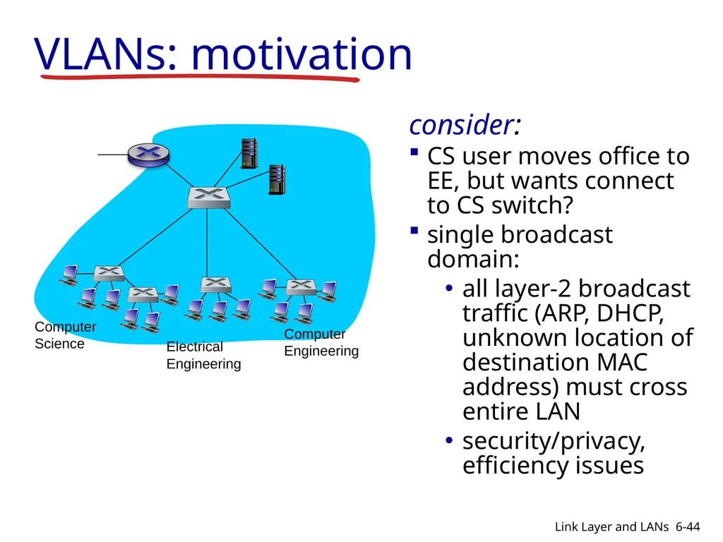
slide44. VLANs: motivation consider:
CS user moves office to EE, but wants connect to CS switch?
single broadcast domain:
all layer-2 broadcast traffic (ARP, DHCP, unknown location of destination MAC address) must cross entire LAN
security/privacy, efficiency issues Computer
Science Electrical
Engineering Computer
Engineering 6-44 Link Layer and LANs<br>
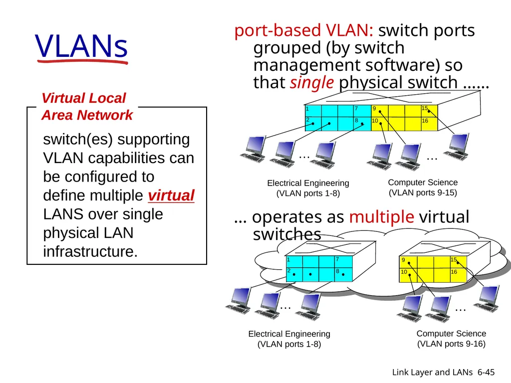
slide45. VLANs port-based VLAN: switch ports grouped (by switch management software) so that single physical switch …… switch(es) supporting VLAN capabilities can be configured to define multiple virtual LANS over single physical LAN infrastructure. Virtual Local
Area Network 1 8 9 16 10 2 7 … Electrical Engineering
(VLAN ports 1-8) Computer Science
(VLAN ports 9-15) 15 … 6-45 Link Layer and LANs<br>
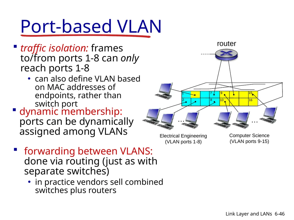
slide46. Port-based VLAN 1 8 9 16 10 2 7 … Electrical Engineering
(VLAN ports 1-8) Computer Science
(VLAN ports 9-15) 15 … traffic isolation: frames to/from ports 1-8 can only reach ports 1-8
can also define VLAN based on MAC addresses of endpoints, rather than switch port dynamic membership: ports can be dynamically assigned among VLANs router 6-46 Link Layer and LANs<br>
slide47. Link layer, LANs: outline 6.1 introduction, services
6.2 error detection, correction
6.3 multiple access protocols
6.4 LANs
addressing, ARP
Ethernet
switches
VLANS 6.5 link virtualization: MPLS 6-47 Link Layer and LANs<br>
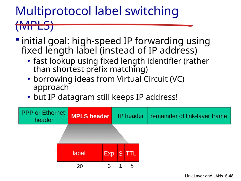
slide48. Multiprotocol label switching (MPLS) initial goal: high-speed IP forwarding using fixed length label (instead of IP address)
fast lookup using fixed length identifier (rather than shortest prefix matching)
borrowing ideas from Virtual Circuit (VC) approach
but IP datagram still keeps IP address! PPP or Ethernet
header IP header remainder of link-layer frame MPLS header label Exp S TTL 20 3 1 5 6-48 Link Layer and LANs<br>
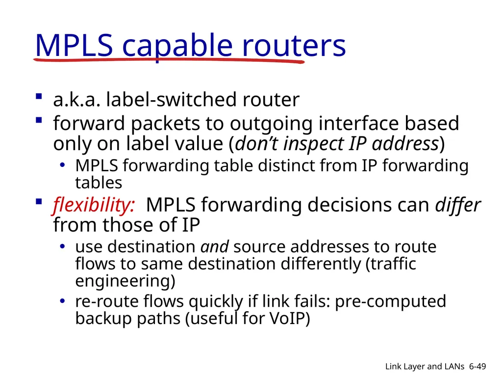
slide49. MPLS capable routers a.k.a. label-switched router
forward packets to outgoing interface based only on label value (don’t inspect IP address)
MPLS forwarding table distinct from IP forwarding tables
flexibility: MPLS forwarding decisions can differ from those of IP
use destination and source addresses to route flows to same destination differently (traffic engineering)
re-route flows quickly if link fails: pre-computed backup paths (useful for VoIP) 6-49 Link Layer and LANs<br>
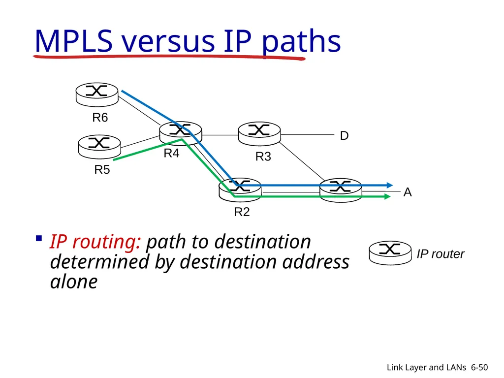
slide50. R2 D R3 R5 A R6 MPLS versus IP paths IP router IP routing: path to destination determined by destination address alone R4 6-50 Link Layer and LANs<br>
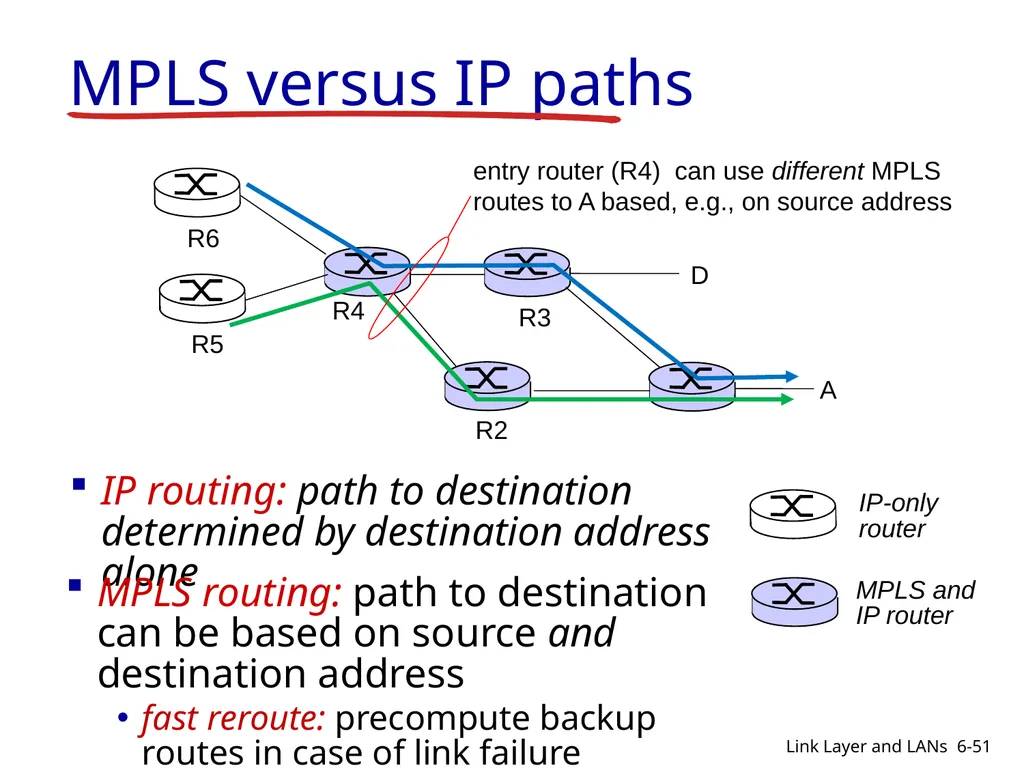
slide51. R2 D R3 R4 R5 A R6 MPLS versus IP paths IP-only
router IP routing: path to destination determined by destination address alone MPLS and
IP router MPLS routing: path to destination can be based on source and destination address
fast reroute: precompute backup routes in case of link failure entry router (R4) can use different MPLS routes to A based, e.g., on source address 6-51 Link Layer and LANs<br>
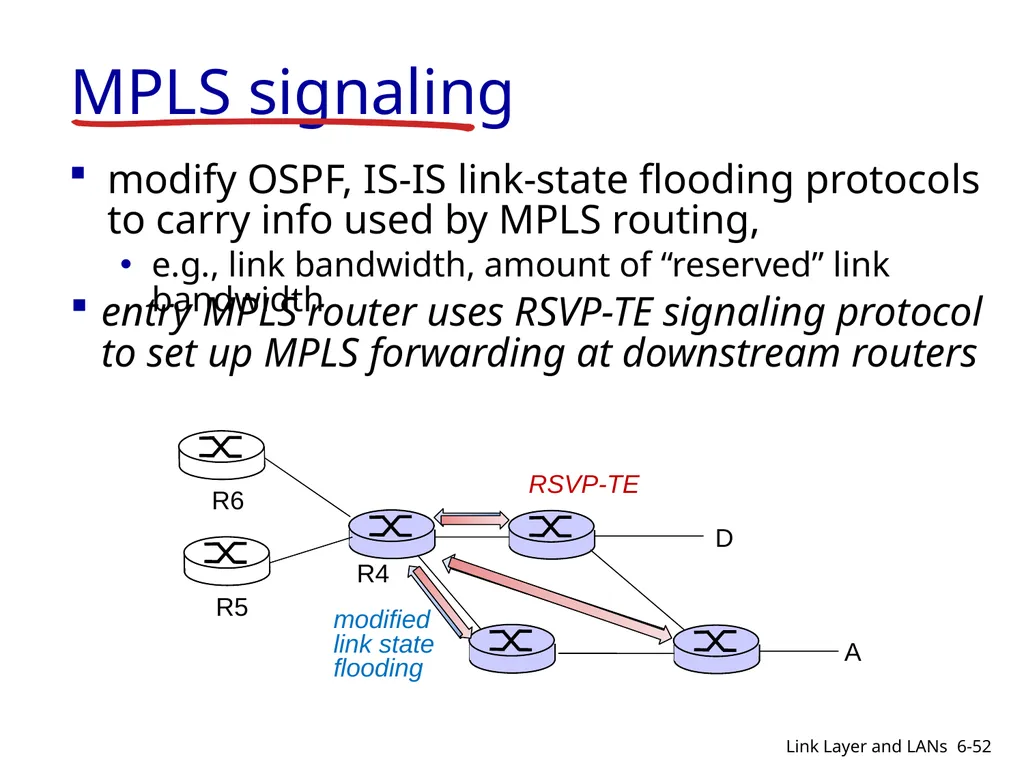
slide52. MPLS signaling modify OSPF, IS-IS link-state flooding protocols to carry info used by MPLS routing,
e.g., link bandwidth, amount of “reserved” link bandwidth D R4 R5 A R6 entry MPLS router uses RSVP-TE signaling protocol to set up MPLS forwarding at downstream routers 6-52 Link Layer and LANs<br>
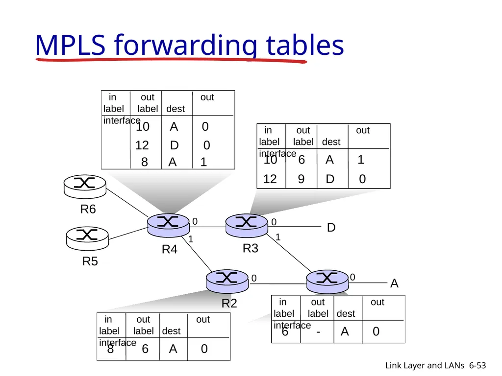
slide53. R1 R2 D R3 R4 R5 0 1 0 0 A R6 in out out
label label dest interface 10 A 0 12 D 0 1 0 8 A 1 MPLS forwarding tables 6-53 Link Layer and LANs<br>
slide54. Link layer, LANs: outline 6.1 introduction, services
6.2 error detection, correction
6.3 multiple access protocols
6.4 LANs
addressing, ARP
Ethernet
switches
VLANS 6.5 link virtualization: MPLS 6-54 Link Layer and LANs<br>
Anduo Wang
Based on Slides created by JFK/KWR 7th edition Jim Kurose, Keith Ross Pearson/Addison Wesley April 2016 Lecture 12 – Chapter 6
Link Layer and LANs<br>
slide2. Chapter 6: Link layer and LANs our goals:
understand principles behind link layer services:
error detection, correction
sharing a broadcast channel: multiple access
link layer addressing
local area networks: Ethernet, VLANs
instantiation, implementation of various link layer technologies 6-2 Link Layer and LANs<br>
slide3. Link layer, LANs: outline 6.1 introduction, services
6.2 error detection, correction
6.3 multiple access protocols
6.4 LANs
addressing, ARP
Ethernet
switches
VLANS 6.5 link virtualization: MPLS 6-3 Link Layer and LANs<br>
slide4. Link layer: introduction terminology:
hosts and routers: nodes
communication channels that connect adjacent nodes along communication path: links
wired links
wireless links
LANs
layer-2 packet: frame, encapsulates datagram data-link layer has responsibility of
transferring datagram from one node
to physically adjacent node over a link 6-4 Link Layer and LANs<br>
slide5. Link layer services framing, link access:
encapsulate datagram into frame, adding header, trailer
channel access if shared medium
“MAC” addresses used in frame headers to identify source, destination
different from IP address!
reliable delivery between adjacent nodes
we learned how to do this already (chapter 3)!
seldom used on low bit-error link (fiber, some twisted pair)
wireless links: high error rates
Q: why both link-level and end-end reliability? 6-5 Link Layer and LANs<br>
slide6. flow control:
pacing between adjacent sending and receiving nodes
error detection:
errors caused by signal attenuation, noise.
receiver detects presence of errors:
signals sender for retransmission or drops frame
error correction:
receiver identifies and corrects bit error(s) without resorting to retransmission
half-duplex and full-duplex
with half duplex, nodes at both ends of link can transmit, but not at same time Link layer services (more) 6-6 Link Layer and LANs<br>
slide7. Link layer, LANs: outline 6.1 introduction, services
6.2 error detection, correction
6.3 multiple access protocols
6.4 LANs
addressing, ARP
Ethernet
switches
VLANS 6.5 link virtualization: MPLS
6.6 data center networking
6.7 a day in the life of a web request 6-7 Link Layer and LANs<br>
slide8. Error detection EDC= Error Detection and Correction bits (redundancy)
D = Data protected by error checking, may include header fields
Error detection not 100% reliable!
protocol may miss some errors, but rarely
larger EDC field yields better detection and correction otherwise 6-8 Link Layer and LANs<br>
slide9. Parity checking single bit parity:
detect single bit errors two-dimensional bit parity:
detect and correct single bit errors 0 0 6-9 Link Layer and LANs * Check out the online interactive exercises for more examples: http://gaia.cs.umass.edu/kurose_ross/interactive/<br>
slide10. Link layer, LANs: outline 6.1 introduction, services
6.2 error detection, correction
6.3 multiple access protocols
6.4 LANs
addressing, ARP
Ethernet
switches
VLANS 6.5 link virtualization: MPLS 6-10 Link Layer and LANs<br>
slide11. Multiple access links, protocols two types of “links”:
point-to-point
PPP for dial-up access
point-to-point link between Ethernet switch, host
broadcast (shared wire or medium)
old-fashioned Ethernet
upstream HFC
802.11 wireless LAN shared wire (e.g.,
cabled Ethernet) shared RF
(e.g., 802.11 WiFi) shared RF
(satellite) humans at a
cocktail party
(shared air, acoustical) 6-11 Link Layer and LANs<br>
slide12. Multiple access protocols single shared broadcast channel
two or more simultaneous transmissions by nodes: interference
collision if node receives two or more signals at the same time
multiple access protocol
distributed algorithm that determines how nodes share channel, i.e., determine when node can transmit
communication about channel sharing must use channel itself!
no out-of-band channel for coordination 6-12 Link Layer and LANs<br>
slide13. An ideal multiple access protocol given: broadcast channel of rate R bps
desiderata:
1. when one node wants to transmit, it can send at rate R.
2. when M nodes want to transmit, each can send at average rate R/M
3. fully decentralized:
no special node to coordinate transmissions
no synchronization of clocks, slots
4. simple 6-13 Link Layer and LANs<br>
slide14. MAC protocols: taxonomy three broad classes:
channel partitioning
divide channel into smaller “pieces” (time slots, frequency, code)
allocate piece to node for exclusive use
random access
channel not divided, allow collisions
“recover” from collisions
“taking turns”
nodes take turns, but nodes with more to send can take longer turns 6-14 Link Layer and LANs<br>
slide15. Summary of MAC protocols channel partitioning, by time, frequency or code
Time Division, Frequency Division
random access (dynamic),
ALOHA, S-ALOHA, CSMA, CSMA/CD
carrier sensing: easy in some technologies (wire), hard in others (wireless)
CSMA/CD used in Ethernet
CSMA/CA used in 802.11
taking turns
polling from central site, token passing
Bluetooth, FDDI, token ring 6-15 Link Layer and LANs<br>
slide16. Link layer, LANs: outline 6.1 introduction, services
6.2 error detection, correction
6.3 multiple access protocols
6.4 LANs
addressing, ARP
Ethernet
switches
VLANS 6.5 link virtualization: MPLS
6.6 data center networking
6.7 a day in the life of a web request 6-16 Link Layer and LANs<br>
slide17. MAC addresses and ARP 32-bit IP address:
network-layer address for interface
used for layer 3 (network layer) forwarding
MAC (or LAN or physical or Ethernet) address:
function: used ‘locally” to get frame from one interface to another physically-connected interface (same network, in IP-addressing sense)
48 bit MAC address (for most LANs) burned in NIC ROM, also sometimes software settable
e.g.: 1A-2F-BB-76-09-AD hexadecimal (base 16) notation
(each “numeral” represents 4 bits) 6-17 Link Layer and LANs<br>
slide18. LAN addresses and ARP each adapter on LAN has unique LAN address adapter 1A-2F-BB-76-09-AD 58-23-D7-FA-20-B0 0C-C4-11-6F-E3-98 71-65-F7-2B-08-53 LAN
(wired or
wireless) 6-18 Link Layer and LANs<br>
slide19. LAN addresses (more) MAC address allocation administered by IEEE
manufacturer buys portion of MAC address space (to assure uniqueness)
analogy:
MAC address: like Social Security Number
IP address: like postal address
MAC flat address ➜ portability
can move LAN card from one LAN to another
IP hierarchical address not portable
address depends on IP subnet to which node is attached 6-19 Link Layer and LANs<br>
slide20. ARP: address resolution protocol ARP table: each IP node (host, router) on LAN has table
IP/MAC address mappings for some LAN nodes:
< IP address; MAC address; TTL>
TTL (Time To Live): time after which address mapping will be forgotten (typically 20 min) 1A-2F-BB-76-09-AD 58-23-D7-FA-20-B0 0C-C4-11-6F-E3-98 71-65-F7-2B-08-53 LAN 137.196.7.23 137.196.7.78 137.196.7.14 137.196.7.88 6-20 Link Layer and LANs<br>
slide21. ARP protocol: same LAN A wants to send datagram to B
B’s MAC address not in A’s ARP table.
A broadcasts ARP query packet, containing B's IP address
destination MAC address = FF-FF-FF-FF-FF-FF
all nodes on LAN receive ARP query
B receives ARP packet, replies to A with its (B's) MAC address
frame sent to A’s MAC address (unicast) A caches (saves) IP-to-MAC address pair in its ARP table until information becomes old (times out)
soft state: information that times out (goes away) unless refreshed
ARP is “plug-and-play”:
nodes create their ARP tables without intervention from net administrator 6-21 Link Layer and LANs<br>
slide22. walkthrough: send datagram from A to B via R
focus on addressing – at IP (datagram) and MAC layer (frame)
assume A knows B’s IP address
assume A knows IP address of first hop router, R (how?)
assume A knows R’s MAC address (how?) Addressing: routing to another LAN 6-22 Link Layer and LANs<br>
slide23. Addressing: routing to another LAN A creates IP datagram with IP source A, destination B A creates link-layer frame with R's MAC address as destination address, frame contains A-to-B IP datagram 6-23 Link Layer and LANs<br>
slide24. Addressing: routing to another LAN frame sent from A to R frame received at R, datagram removed, passed up to IP 6-24 Link Layer and LANs<br>
slide25. Addressing: routing to another LAN R forwards datagram with IP source A, destination B R creates link-layer frame with B's MAC address as destination address, frame contains A-to-B IP datagram 6-25 Link Layer and LANs<br>
slide26. Addressing: routing to another LAN R forwards datagram with IP source A, destination B R creates link-layer frame with B's MAC address as destination address, frame contains A-to-B IP datagram 6-26 Link Layer and LANs<br>
slide27. R 1A-23-F9-CD-06-9B 222.222.222.220 CC-49-DE-D0-AB-7D 111.111.111.112 111.111.111.111 74-29-9C-E8-FF-55 A 222.222.222.221 88-B2-2F-54-1A-0F B Addressing: routing to another LAN R forwards datagram with IP source A, destination B R creates link-layer frame with B's MAC address as dest, frame contains A-to-B IP datagram 6-27 Link Layer and LANs * Check out the online interactive exercises for more examples: http://gaia.cs.umass.edu/kurose_ross/interactive/<br>
slide28. Link layer, LANs: outline 6.1 introduction, services
6.2 error detection, correction
6.3 multiple access protocols
6.4 LANs
addressing, ARP
Ethernet
switches
VLANS 6.5 link virtualization: MPLS 6-28 Link Layer and LANs<br>
slide29. Ethernet “dominant” wired LAN technology:
single chip, multiple speeds (e.g., Broadcom BCM5761)
first widely used LAN technology
simpler, cheap
kept up with speed race: 10 Mbps – 10 Gbps Metcalfe’s Ethernet sketch 6-29 Link Layer and LANs<br>
slide30. Ethernet: physical topology bus: popular through mid 90s
all nodes in same collision domain (can collide with each other)
star: prevails today
active switch in center
each “spoke” runs a (separate) Ethernet protocol (nodes do not collide with each other) switch bus: coaxial cable star 6-30 Link Layer and LANs<br>
slide31. Ethernet: unreliable, connectionless connectionless: no handshaking between sending and receiving NICs
unreliable: receiving NIC doesn't send acks or nacks to sending NIC
data in dropped frames recovered only if initial sender uses higher layer rdt (e.g., TCP), otherwise dropped data lost
Ethernet’s MAC protocol: unslotted CSMA/CD with binary backoff 6-31 Link Layer and LANs<br>
slide32. Link layer, LANs: outline 6.1 introduction, services
6.2 error detection, correction
6.3 multiple access protocols
6.4 LANs
addressing, ARP
Ethernet
switches
VLANS 6.5 link virtualization: MPLS 6-32 Link Layer and LANs<br>
slide33. Ethernet switch link-layer device: takes an active role
store, forward Ethernet frames
examine incoming frame’s MAC address, selectively forward frame to one-or-more outgoing links when frame is to be forwarded on segment, uses CSMA/CD to access segment
transparent
hosts are unaware of presence of switches
plug-and-play, self-learning
switches do not need to be configured 6-33 Link Layer and LANs<br>
slide34. Switch: multiple simultaneous transmissions hosts have dedicated, direct connection to switch
switches buffer packets
Ethernet protocol used on each incoming link, but no collisions; full duplex
each link is its own collision domain
switching: A-to-A’ and B-to-B’ can transmit simultaneously, without collisions 6-34 Link Layer and LANs<br>
slide35. Switch forwarding table Q: how does switch know A’ reachable via interface 4, B’ reachable via interface 5? A: each switch has a switch table, each entry:
(MAC address of host, interface to reach host, time stamp)
looks like a routing table! Q: how are entries created, maintained in switch table?
something like a routing protocol? 6-35 Link Layer and LANs<br>
slide36. Switch: self-learning switch learns which hosts can be reached through which interfaces
when frame received, switch “learns” location of sender: incoming LAN segment
records sender/location pair in switch table Switch table
(initially empty) 6-36 Link Layer and LANs<br>
slide37. Switch: frame filtering/forwarding when frame received at switch:
1. record incoming link, MAC address of sending host
2. index switch table using MAC destination address
3. if entry found for destination then {
if destination on segment from which frame arrived then drop frame
else forward frame on interface indicated by entry
}
else flood /* forward on all interfaces except arriving
interface */ 6-37 Link Layer and LANs<br>
slide38. Self-learning, forwarding: example switch table
(initially empty) frame destination, A’, location unknown: flood destination A location known: selectively send
on just one link 6-38 Link Layer and LANs<br>
slide39. Interconnecting switches self-learning switches can be connected together: Q: sending from A to G - how does S1 know to forward frame destined to G via S4 and S3?
A: self learning! (works exactly the same as in single-switch case!) 6-39 Link Layer and LANs<br>
slide40. Self-learning multi-switch example Suppose C sends frame to I, I responds to C Q: show switch tables and packet forwarding in S1, S2, S3, S4 6-40 Link Layer and LANs<br>
slide41. Institutional network to external
network router IP subnet mail server web server 6-41 Link Layer and LANs<br>
slide42. Switches vs. routers both are store-and-forward:
routers: network-layer devices (examine network-layer headers)
switches: link-layer devices (examine link-layer headers)
both have forwarding tables:
routers: compute tables using routing algorithms, IP addresses
switches: learn forwarding table using flooding, learning, MAC addresses application
transport
network
link
physical switch application
transport
network
link
physical 6-42 Link Layer and LANs<br>
slide43. Link layer, LANs: outline 6.1 introduction, services
6.2 error detection, correction
6.3 multiple access protocols
6.4 LANs
addressing, ARP
Ethernet
switches
VLANS 6.5 link virtualization: MPLS 6-43 Link Layer and LANs<br>
slide44. VLANs: motivation consider:
CS user moves office to EE, but wants connect to CS switch?
single broadcast domain:
all layer-2 broadcast traffic (ARP, DHCP, unknown location of destination MAC address) must cross entire LAN
security/privacy, efficiency issues Computer
Science Electrical
Engineering Computer
Engineering 6-44 Link Layer and LANs<br>
slide45. VLANs port-based VLAN: switch ports grouped (by switch management software) so that single physical switch …… switch(es) supporting VLAN capabilities can be configured to define multiple virtual LANS over single physical LAN infrastructure. Virtual Local
Area Network 1 8 9 16 10 2 7 … Electrical Engineering
(VLAN ports 1-8) Computer Science
(VLAN ports 9-15) 15 … 6-45 Link Layer and LANs<br>
slide46. Port-based VLAN 1 8 9 16 10 2 7 … Electrical Engineering
(VLAN ports 1-8) Computer Science
(VLAN ports 9-15) 15 … traffic isolation: frames to/from ports 1-8 can only reach ports 1-8
can also define VLAN based on MAC addresses of endpoints, rather than switch port dynamic membership: ports can be dynamically assigned among VLANs router 6-46 Link Layer and LANs<br>
slide47. Link layer, LANs: outline 6.1 introduction, services
6.2 error detection, correction
6.3 multiple access protocols
6.4 LANs
addressing, ARP
Ethernet
switches
VLANS 6.5 link virtualization: MPLS 6-47 Link Layer and LANs<br>
slide48. Multiprotocol label switching (MPLS) initial goal: high-speed IP forwarding using fixed length label (instead of IP address)
fast lookup using fixed length identifier (rather than shortest prefix matching)
borrowing ideas from Virtual Circuit (VC) approach
but IP datagram still keeps IP address! PPP or Ethernet
header IP header remainder of link-layer frame MPLS header label Exp S TTL 20 3 1 5 6-48 Link Layer and LANs<br>
slide49. MPLS capable routers a.k.a. label-switched router
forward packets to outgoing interface based only on label value (don’t inspect IP address)
MPLS forwarding table distinct from IP forwarding tables
flexibility: MPLS forwarding decisions can differ from those of IP
use destination and source addresses to route flows to same destination differently (traffic engineering)
re-route flows quickly if link fails: pre-computed backup paths (useful for VoIP) 6-49 Link Layer and LANs<br>
slide50. R2 D R3 R5 A R6 MPLS versus IP paths IP router IP routing: path to destination determined by destination address alone R4 6-50 Link Layer and LANs<br>
slide51. R2 D R3 R4 R5 A R6 MPLS versus IP paths IP-only
router IP routing: path to destination determined by destination address alone MPLS and
IP router MPLS routing: path to destination can be based on source and destination address
fast reroute: precompute backup routes in case of link failure entry router (R4) can use different MPLS routes to A based, e.g., on source address 6-51 Link Layer and LANs<br>
slide52. MPLS signaling modify OSPF, IS-IS link-state flooding protocols to carry info used by MPLS routing,
e.g., link bandwidth, amount of “reserved” link bandwidth D R4 R5 A R6 entry MPLS router uses RSVP-TE signaling protocol to set up MPLS forwarding at downstream routers 6-52 Link Layer and LANs<br>
slide53. R1 R2 D R3 R4 R5 0 1 0 0 A R6 in out out
label label dest interface 10 A 0 12 D 0 1 0 8 A 1 MPLS forwarding tables 6-53 Link Layer and LANs<br>
slide54. Link layer, LANs: outline 6.1 introduction, services
6.2 error detection, correction
6.3 multiple access protocols
6.4 LANs
addressing, ARP
Ethernet
switches
VLANS 6.5 link virtualization: MPLS 6-54 Link Layer and LANs<br>