
3.CNC PART PROGRAMMING Co:-Develop part program



Description: 3.CNC PART PROGRAMMING Co:-Develop part program for CNC Turning, Milling and verify on simulation software. Visit for more Learning Resources PART PROGRAM A part program is a series of coded instructions required to produce a part. It
Related Topics
Download Presentation
"3.CNC PART PROGRAMMING Co:-Develop part program" is the property of its rightful owner. Permission is granted to download and print the materials on this website for personal, non-commercial use only, and to display it on your personal computer provided you do not modify the materials and that you retain all copyright notices contained in the materials. By downloading content from our website, you accept the terms of this agreement.
Presentation Transcript
slide1. 3.CNC PART PROGRAMMING Co:-Develop part program for CNC Turning, Milling and verify on simulation software. Visit for more Learning Resources<br>
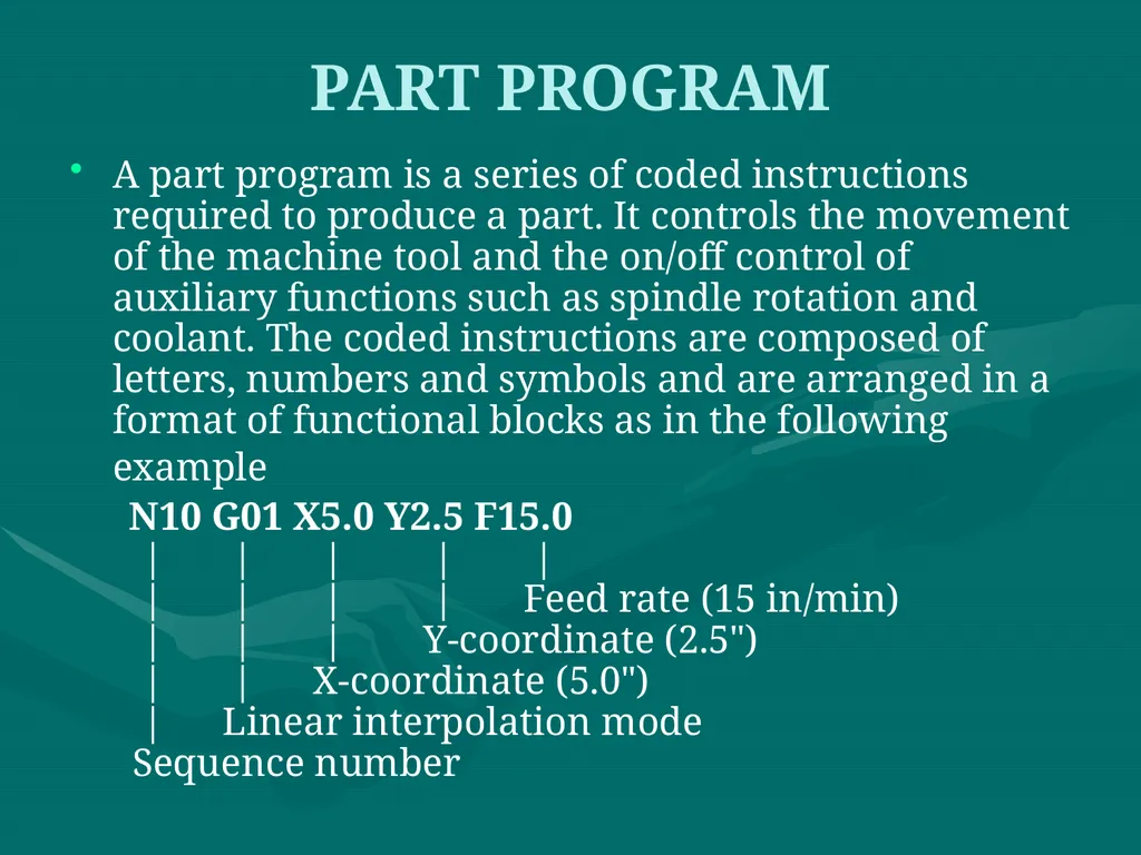
slide2. PART PROGRAM A part program is a series of coded instructions required to produce a part. It controls the movement of the machine tool and the on/off control of auxiliary functions such as spindle rotation and coolant. The coded instructions are composed of letters, numbers and symbols and are arranged in a format of functional blocks as in the following example
N10 G01 X5.0 Y2.5 F15.0 | | | | | | | | | Feed rate (15 in/min) | | | Y-coordinate (2.5") | | X-coordinate (5.0") | Linear interpolation mode Sequence number<br>
slide3. PROGRAM INPUT DEVICE The program input device is the mechanism for part programs to be entered into the CNC control. The most commonly used program input devices are keyboards, punched tape reader, diskette drivers, throgh RS 232 serial ports and networks.<br>
slide4. MACHINE CONTROL UNIT The machine control unit (MCU) is the heart of a CNC system. It is used to perform the following functions:
Read coded instructions
Decode coded instructions
Implement interpolations (linear, circular, and helical) to generate axis motion commands
Feed axis motion commands to the amplifier circuits for driving the axis mechanisms
Receive the feedback signals of position and speed for each drive axis
Implement auxiliary control functions such as coolant or spindle on/off, and tool change<br>
slide5. CNC PROGRAMMING Offline programming linked to CAD programs.
Conversational programming by the operator.
MDI ~ Manual Data Input.
Manual Control using jog buttons or `electronic handwheel'.
Word-Address Coding using standard G-codes and M-codes.<br>
slide6. The position of the tool is described by using a Cartesian coordinate system. If (0,0,0) position can be described by the operator, then it is called floating zero.<br>
slide7. In defining the motion of the tool from one point to another, either absolute positioning mode or incremental positioning mode can be used.<br>
slide8. 1. Absolute positioning. In this mode, the desired target position of the tool for a particular move is given relative to the origin point of the program. 2. Incremental positioning. In this mode, the next target position for the tool is given relative to the current tool position.<br>
slide9. Structure of an NC Part Program: Commands are input into the controller in units called blocks or statements. Block Format: 1. Fixed sequential format
2. Tab sequential format
3. Word address format<br>
slide10. EXAMPLE: Assume that a drilling operation is to be programmed as: 1. The tool is positioned at (25.4,12.5,0) by a rapid movement.
2. The tool is then advanced -10 mm in the z direction at a feed rate of 500 mm/min., with the flood coolant on.
3.The is then retracted back 10 mm at the rapid feed rate, and the coolant is turned off.<br>
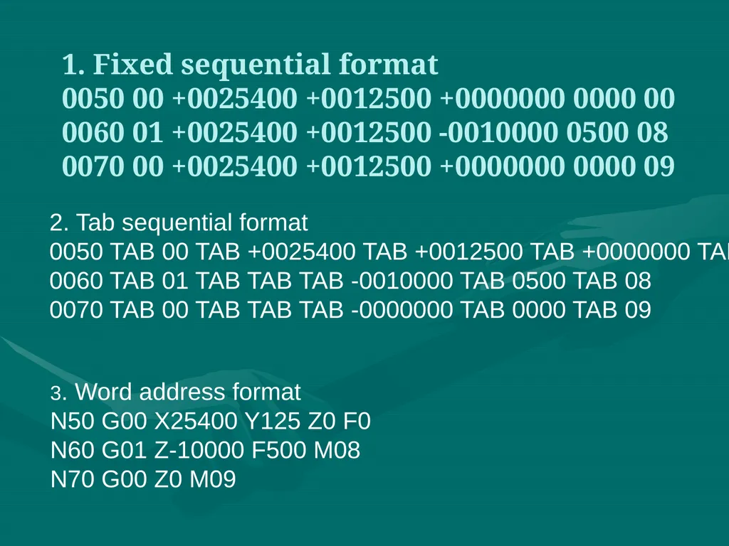
slide11. 1. Fixed sequential format 0050 00 +0025400 +0012500 +0000000 0000 00 0060 01 +0025400 +0012500 -0010000 0500 08 0070 00 +0025400 +0012500 +0000000 0000 09 2. Tab sequential format
0050 TAB 00 TAB +0025400 TAB +0012500 TAB +0000000 TAB
0060 TAB 01 TAB TAB TAB -0010000 TAB 0500 TAB 08
0070 TAB 00 TAB TAB TAB -0000000 TAB 0000 TAB 09 3. Word address format
N50 G00 X25400 Y125 Z0 F0
N60 G01 Z-10000 F500 M08
N70 G00 Z0 M09<br>
slide12. Modal commands: Commands issued in the NC program that will stay in effect until it is changed by some other command, like, feed rate selection, coolant selection, etc. Nonmodal commands: Commands that are effective only when issued and whose effects are lost for subsequent commands, like, a dwell command which instructs the tool to remain in a given configuration for a given amount of time.<br>
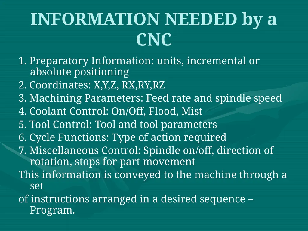
slide13. INFORMATION NEEDED by a CNC 1. Preparatory Information: units, incremental or absolute positioning
2. Coordinates: X,Y,Z, RX,RY,RZ
3. Machining Parameters: Feed rate and spindle speed
4. Coolant Control: On/Off, Flood, Mist
5. Tool Control: Tool and tool parameters
6. Cycle Functions: Type of action required
7. Miscellaneous Control: Spindle on/off, direction of rotation, stops for part movement
This information is conveyed to the machine through a set
of instructions arranged in a desired sequence – Program.<br>
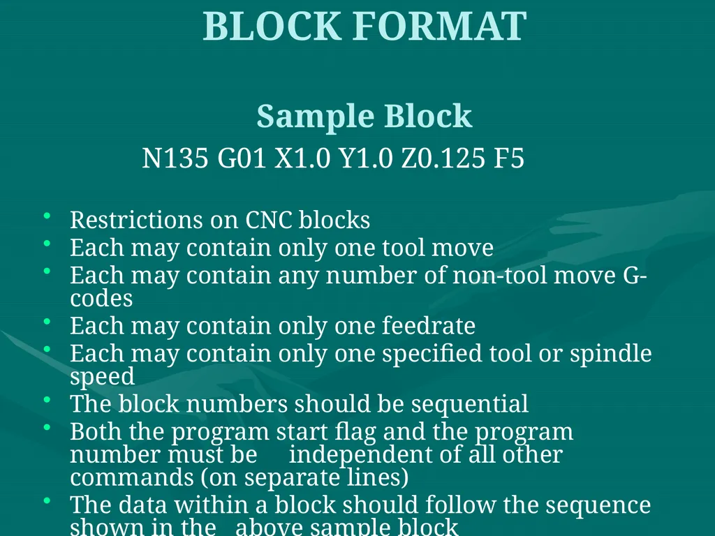
slide14. BLOCK FORMAT Sample Block N135 G01 X1.0 Y1.0 Z0.125 F5
Restrictions on CNC blocks
Each may contain only one tool move
Each may contain any number of non-tool move G-codes
Each may contain only one feedrate
Each may contain only one specified tool or spindle speed
The block numbers should be sequential
Both the program start flag and the program number must be independent of all other commands (on separate lines)
The data within a block should follow the sequence shown in the above sample block<br>
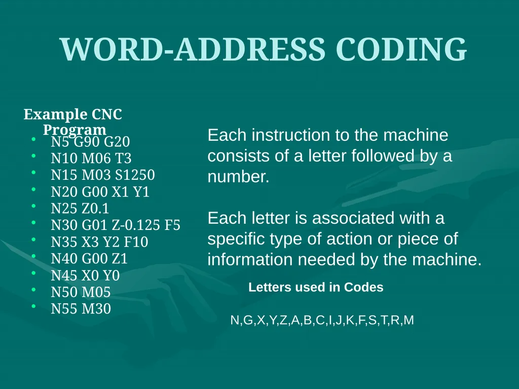
slide15. WORD-ADDRESS CODING N5 G90 G20
N10 M06 T3
N15 M03 S1250
N20 G00 X1 Y1
N25 Z0.1
N30 G01 Z-0.125 F5
N35 X3 Y2 F10
N40 G00 Z1
N45 X0 Y0
N50 M05
N55 M30 Example CNC Program Each instruction to the machine consists of a letter followed by a number.
Each letter is associated with a specific type of action or piece of information needed by the machine. Letters used in Codes N,G,X,Y,Z,A,B,C,I,J,K,F,S,T,R,M<br>
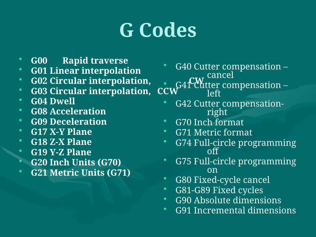
slide16. G Codes G00 Rapid traverse
G01 Linear interpolation
G02 Circular interpolation, CW
G03 Circular interpolation, CCW
G04 Dwell
G08 Acceleration
G09 Deceleration
G17 X-Y Plane
G18 Z-X Plane
G19 Y-Z Plane
G20 Inch Units (G70)
G21 Metric Units (G71) G40 Cutter compensation – cancel
G41 Cutter compensation – left
G42 Cutter compensation- right
G70 Inch format
G71 Metric format
G74 Full-circle programming off
G75 Full-circle programming on
G80 Fixed-cycle cancel
G81-G89 Fixed cycles
G90 Absolute dimensions
G91 Incremental dimensions<br>
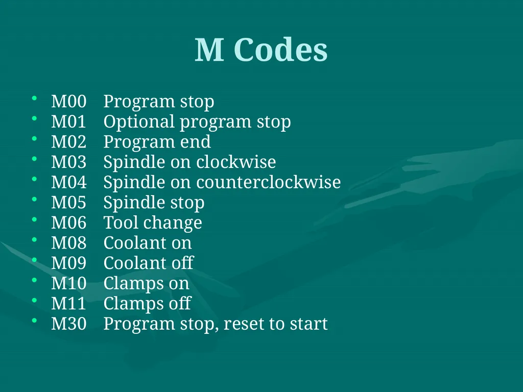
slide17. M Codes M00 Program stop
M01 Optional program stop
M02 Program end
M03 Spindle on clockwise
M04 Spindle on counterclockwise
M05 Spindle stop
M06 Tool change
M08 Coolant on
M09 Coolant off
M10 Clamps on
M11 Clamps off
M30 Program stop, reset to start<br>
slide18. N Codes Gives an identifying number for each block of information.
It is generally good practice to increment each block number by 5 or 10 to allow additional blocks to be inserted if future changes are required.<br>
slide19. X,Y, and Z Codes X, Y, and Z codes are used to specify the coordinate axis.
Number following the code defines the coordinate at the end of the move relative to an incremental or absolute reference point.<br>
slide20. I,J, and K Codes I, J, and K codes are used to specify the coordinate axis when defining the center of a circle.
Number following the code defines the respective coordinate for the center of the circle.<br>
slide21. F,S, and T Codes F-code: used to specify the feed rate
S-code: used to specify the spindle speed
T-code: used to specify the tool identification number associated with the tool to be used in subsequent operations.<br>
slide22. Application of Some Codes G01 Linear Interpolation Format: N_ G01 X_ Y_ Z_ F_
Linear Interpolation results in a straight line feed move.
Unless tool compensation is used, the coordinates are associated with the centerline of the tool.<br>
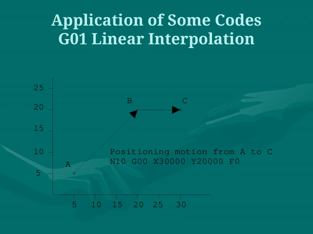
slide23. Application of Some Codes G01 Linear Interpolation . As an example, for the motion that occurs in x-y plane with the same maximum speed for the x- and y-axis, initial motion is at an angle of 45o to the axes until motion in one of
the axes is completed and then the balance of the motion occurs in the other axis. This is called point-to-point motion.<br>
slide24. Application of Some Codes G01 Linear Interpolation<br>
slide25. N10 G00 X1 Z1 N15 Z0.1 N20 G01 Z-0.125 F5 N25 X2 Z2 F10 G01 Linear Interpolation X Z<br>
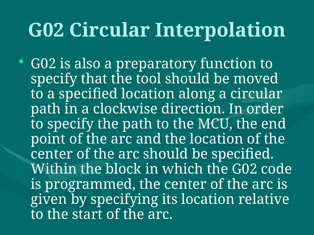
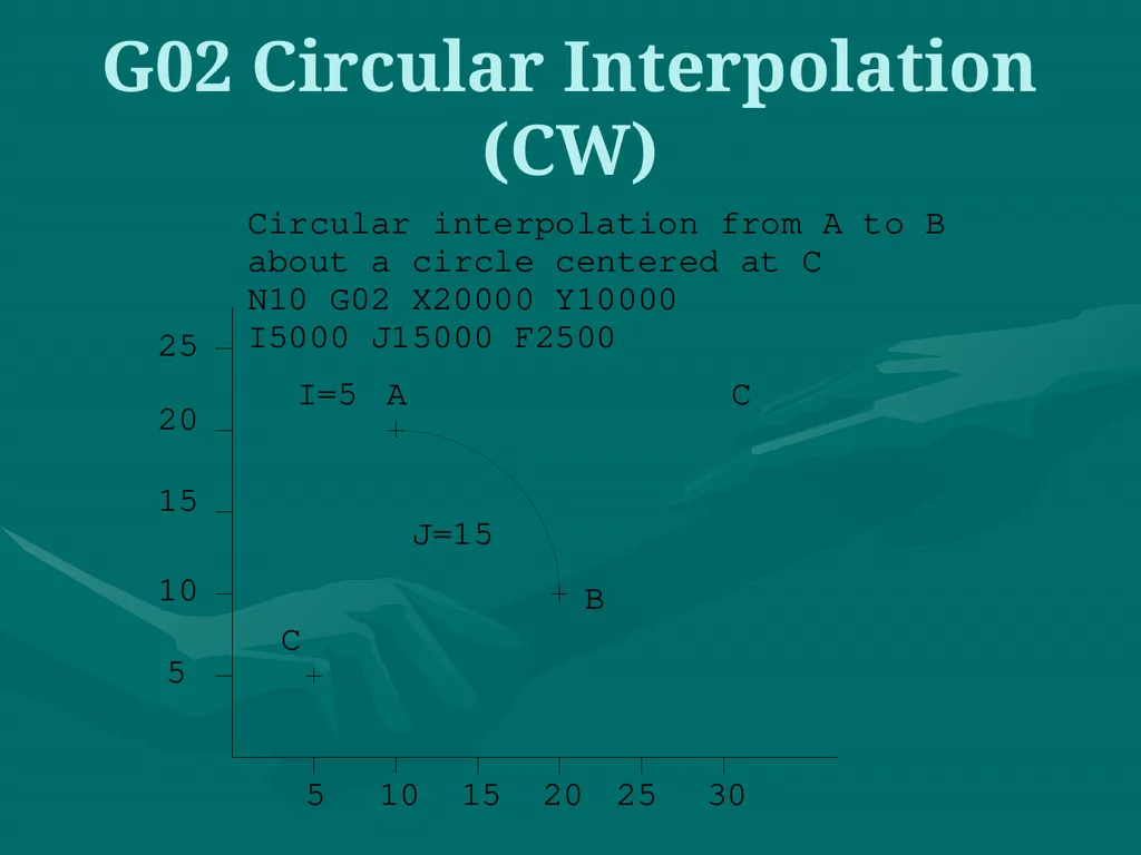
slide26. G02 Circular Interpolation G02 is also a preparatory function to specify that the tool should be moved to a specified location along a circular path in a clockwise direction. In order to specify the path to the MCU, the end point of the arc and the location of the center of the arc should be specified. Within the block in which the G02 code is programmed, the center of the arc is given by specifying its location relative to the start of the arc.<br>
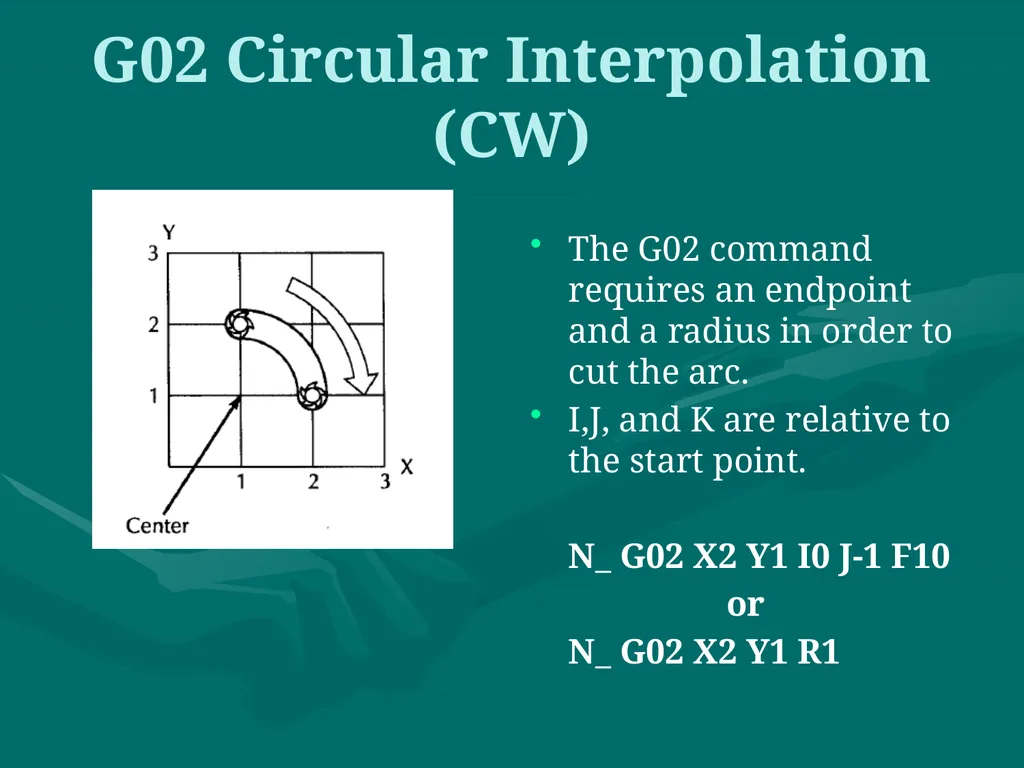
slide27. G02 Circular Interpolation (CW) The G02 command requires an endpoint and a radius in order to cut the arc.
I,J, and K are relative to the start point.
N_ G02 X2 Y1 I0 J-1 F10
or
N_ G02 X2 Y1 R1<br>
slide28. G02 Circular Interpolation (CW)<br>
slide29. The sequence of some machining operations is may be the same for any part and for any machine. For example, drilling a hole involves the following steps:
Position the tool above the point where the hole will be drilled
Set the correct spindle speed
Feed the tool into the workpiece at a controlled feed rate to a predetermined depth
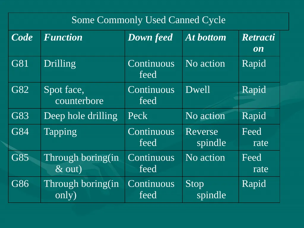
Retract the tool at a rapid rate to just above the point where the hole started Canned Cycles<br>
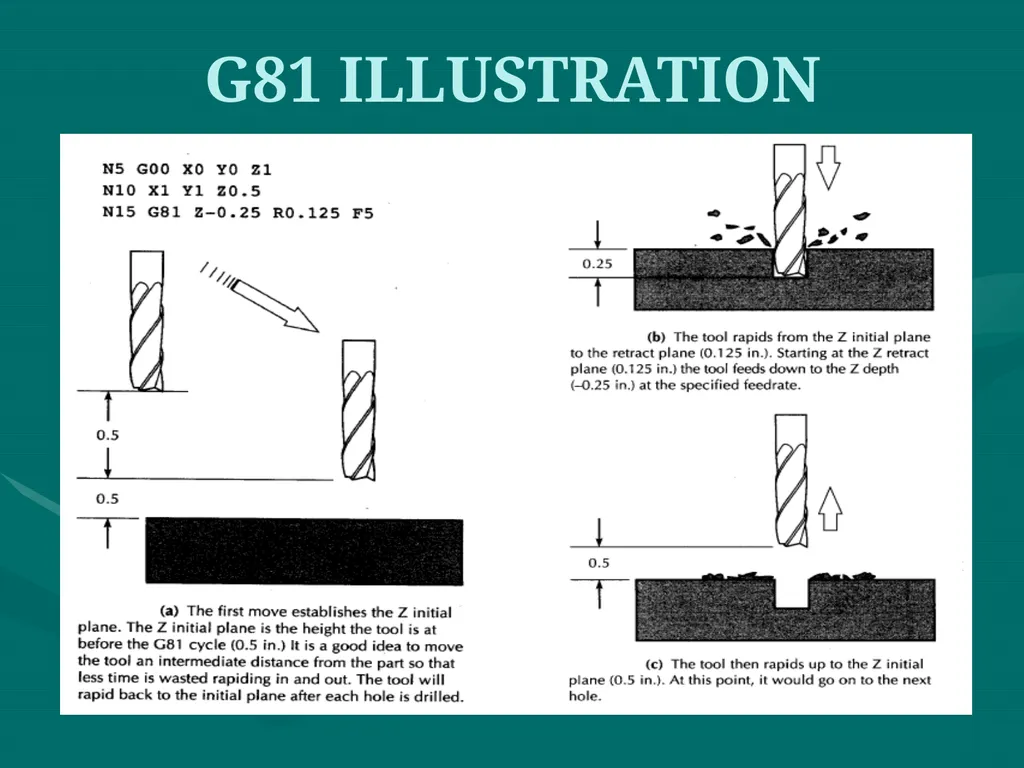
slide31. G81 ILLUSTRATION<br>
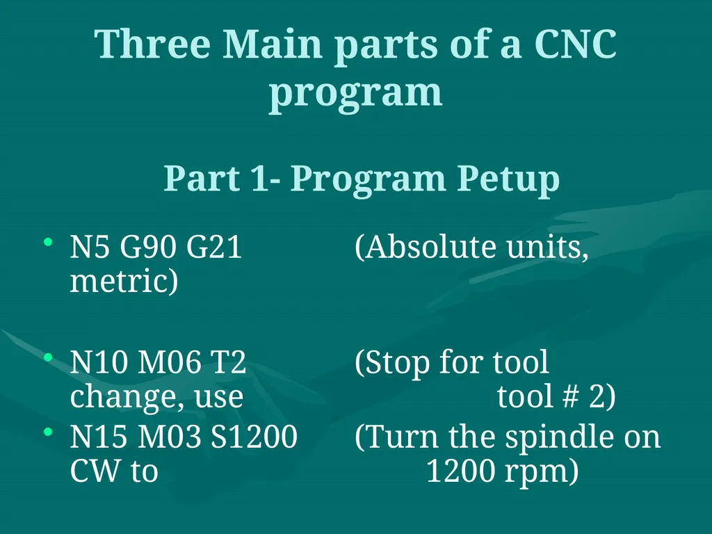
slide32. Three Main parts of a CNC program N5 G90 G21 (Absolute units, metric)
N10 M06 T2 (Stop for tool change, use tool # 2)
N15 M03 S1200 (Turn the spindle on CW to 1200 rpm) Part 1- Program Petup<br>
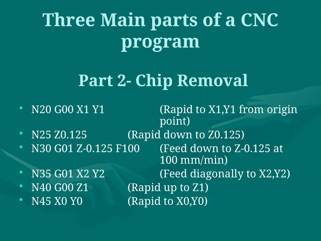
slide33. Three Main parts of a CNC program N20 G00 X1 Y1 (Rapid to X1,Y1 from origin point)
N25 Z0.125 (Rapid down to Z0.125)
N30 G01 Z-0.125 F100 (Feed down to Z-0.125 at 100 mm/min)
N35 G01 X2 Y2 (Feed diagonally to X2,Y2)
N40 G00 Z1 (Rapid up to Z1)
N45 X0 Y0 (Rapid to X0,Y0) Part 2- Chip Removal<br>
slide34. Three Main parts of a CNC program N50 M05 (Turn the spindle off)
N55 M00 (Program stop) Part 3- System Shutdown<br>
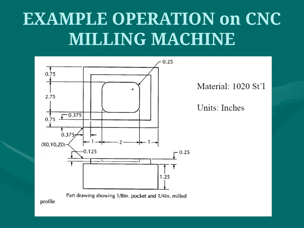
slide35. EXAMPLE OPERATION on CNC MILLING MACHINE<br>
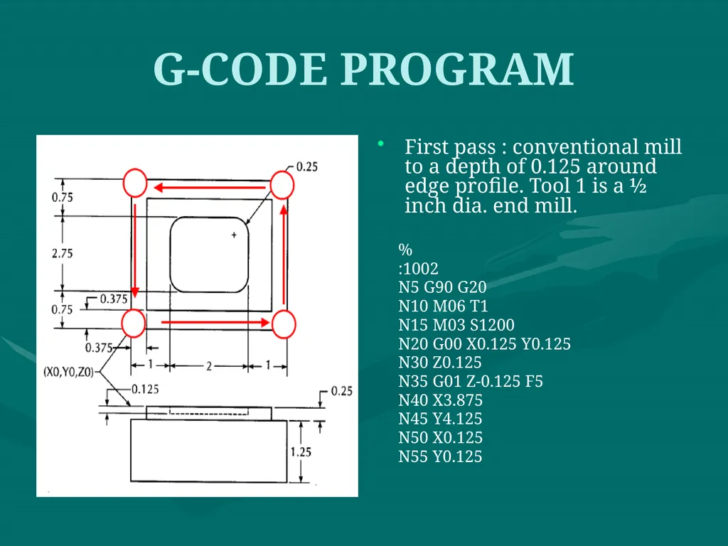
slide36. G-CODE PROGRAM First pass : conventional mill to a depth of 0.125 around edge profile. Tool 1 is a ½ inch dia. end mill.
%
:1002
N5 G90 G20
N10 M06 T1
N15 M03 S1200
N20 G00 X0.125 Y0.125
N30 Z0.125
N35 G01 Z-0.125 F5
N40 X3.875
N45 Y4.125
N50 X0.125
N55 Y0.125<br>
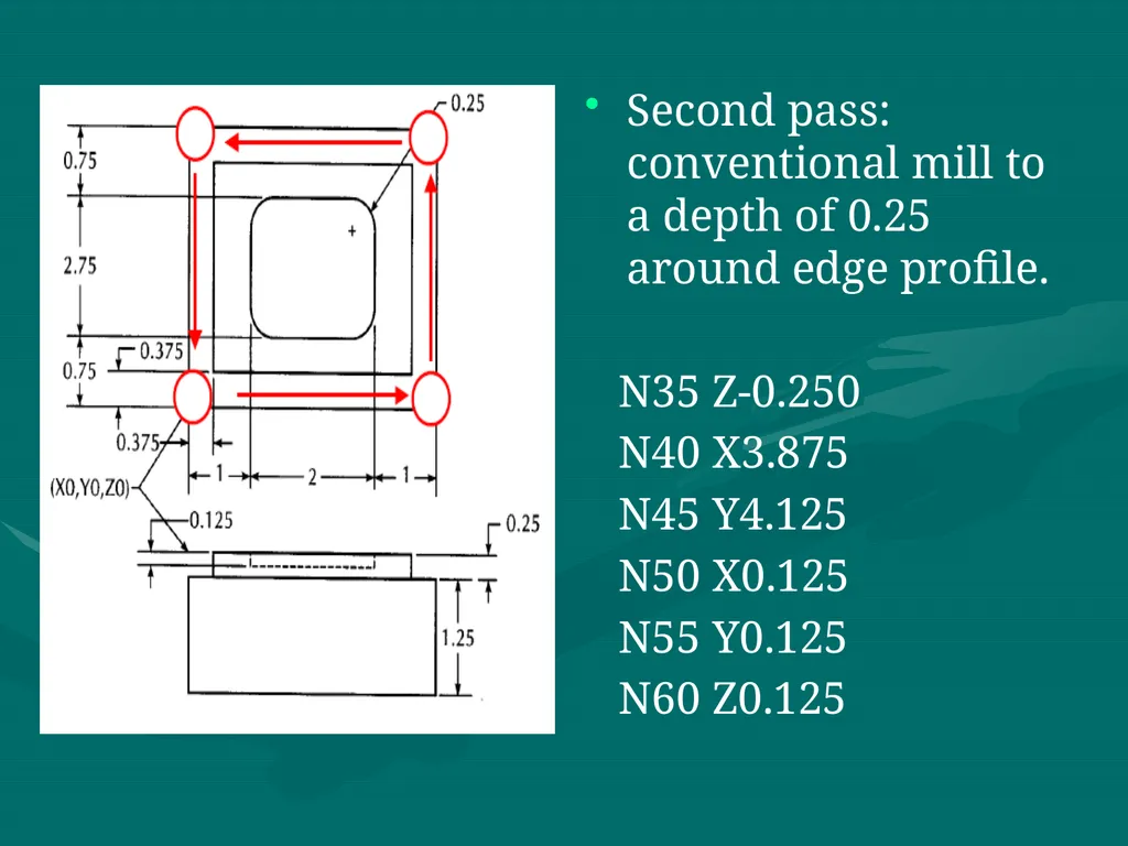
slide37. Second pass: conventional mill to a depth of 0.25 around edge profile.
N35 Z-0.250
N40 X3.875
N45 Y4.125
N50 X0.125
N55 Y0.125
N60 Z0.125<br>
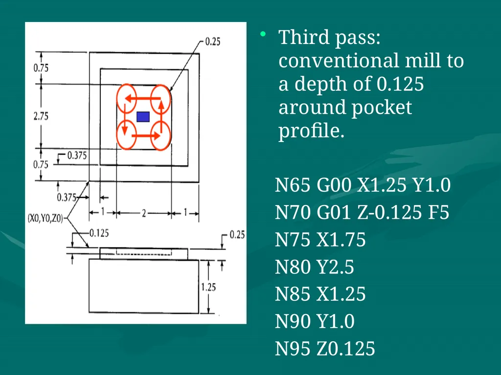
slide38. Third pass: conventional mill to a depth of 0.125 around pocket profile.
N65 G00 X1.25 Y1.0
N70 G01 Z-0.125 F5
N75 X1.75
N80 Y2.5
N85 X1.25
N90 Y1.0
N95 Z0.125<br>
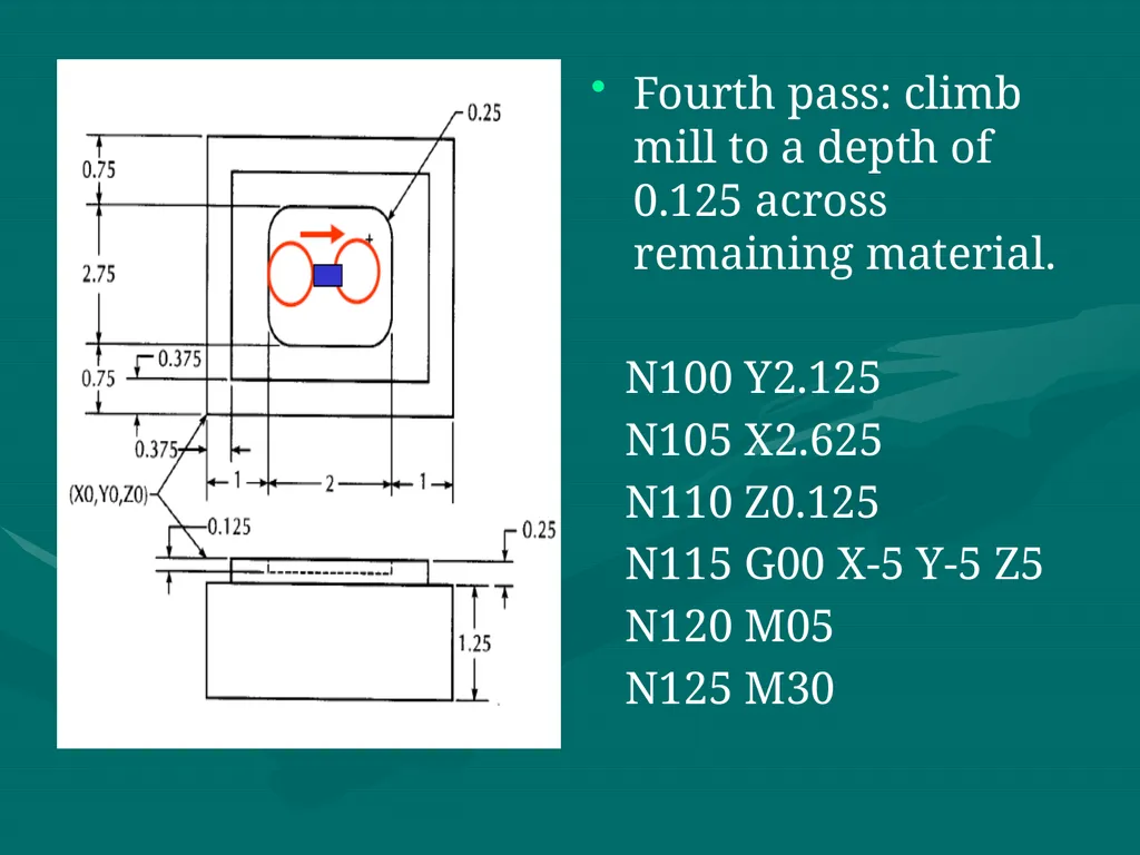
slide39. Fourth pass: climb mill to a depth of 0.125 across remaining material.
N100 Y2.125
N105 X2.625
N110 Z0.125
N115 G00 X-5 Y-5 Z5
N120 M05
N125 M30<br>
slide40. Advanced features:
Execution of the part of the program in a rotated or mirrored position.
Ability to scale the program and produce larger or smaller programs.
Three dimensional circular interpolation which produces a helical shape.
Parabolic and cubic interpolation.<br>
slide41. NC program preparation may be tedious and difficult if the part to be machined has a complex geometry. The main difficulty is to find out the cutter locations during the machining. Computers may be used to assist the programmers in preparing the NC codes. Computer Aided Part Programming:<br>
slide42. Advantages of applying computer-aided part programming include the following:
1. It reduces the manual calculations involves in determining the geometric characteristics of the part.
It provides the cutter path simulation.
It provides tool collision checking.
It shortens the program preparation time.
It makes the program preparation easier.<br>
slide43. The Aerospace Industries Association sponsored the work that led to the first part programming language, developed in MIT in 1955.
This was called: Automatically Programmed Tools (APT).
APT is an English like simple programming language which basically produce the Cutter Location (CL) data.
Using the cutter location data, the program can generate the actual NC codes by using a postprocessor .<br>
slide44. The output of any CAD package include the geometric data of the part to be machined. Therefore, many CAD/CAM package can produce cutter location (CL) data to be used for NC code generation.
There is still to be a process planning module for a workable NC code generation.
Some of the CAD/CAM packages that have the NC code generation capabilities are Computervision, CATIA, CADAM, ProEngineer, MechanicalDesktop (Auto Desk). CAD/CAM Based Part Programming:<br>
slide45. CNC Prg. Basics 45 CNC Programming Basics Program structure
Every program consists of:
Program Start The program start is the program number. The program number begins with character/letter O.
Program Contents NC blocks
Program End M30 for a main program M17 for a sub-program<br>
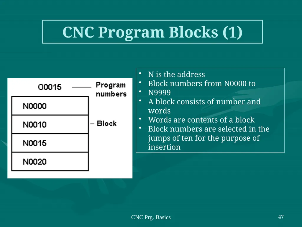
slide46. CNC Prg. Basics 46 CNC Program Numbers Program Numbers
O6999
.
.
.
O0256
O0255
.
.
.
O0000<br>
slide47. CNC Prg. Basics 47 CNC Program Blocks (1) N is the address
Block numbers from N0000 to
N9999
A block consists of number and words
Words are contents of a block
Block numbers are selected in the jumps of ten for the purpose of insertion<br>
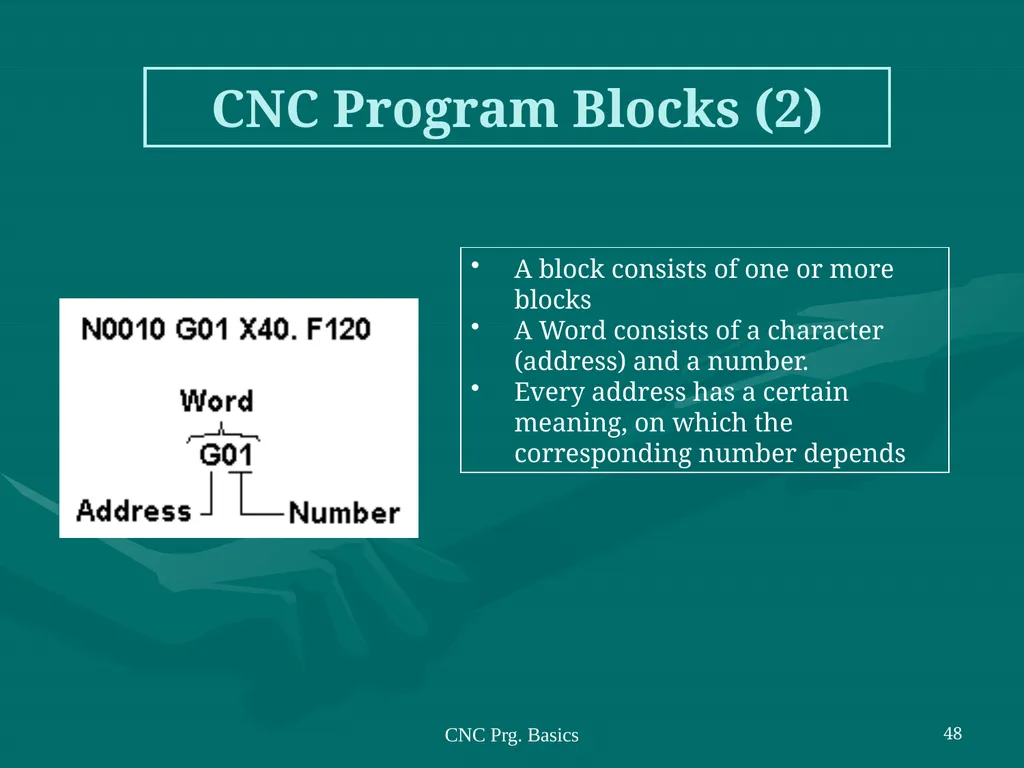
slide48. CNC Prg. Basics 48 CNC Program Blocks (2) A block consists of one or more blocks
A Word consists of a character (address) and a number.
Every address has a certain meaning, on which the corresponding number depends<br>
slide49. CNC Prg. Basics 49 CNC Prg. Syntax Regulations The maximum block length must not exceeded four lines. If max. length exceeded alarm 650 occurs.
Every block starts with a block number.
After the block numbers follows the G command.
Words consists of coordinates X(U), Z(W).
For G02, G03 program interpolation parameter I and K are placed after X(U), Z(W).
The F word (feed, thread pitch).
The S word (cutting speed).
The T word (tool address).
The M word (additional functions).<br>
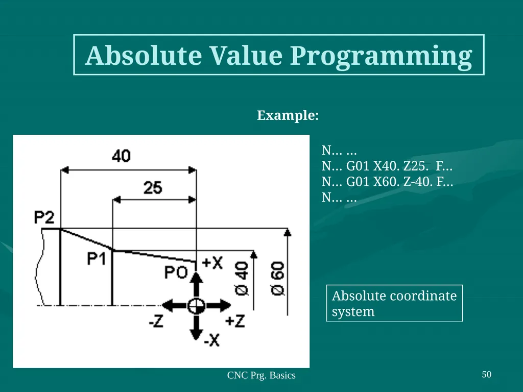
slide50. CNC Prg. Basics 50 Absolute Value Programming P0 N… …
P0 P1 N… G01 X40. Z25. F…
P1 P2 N… G01 X60. Z-40. F…
P2 N… … Absolute coordinate
system Example:<br>
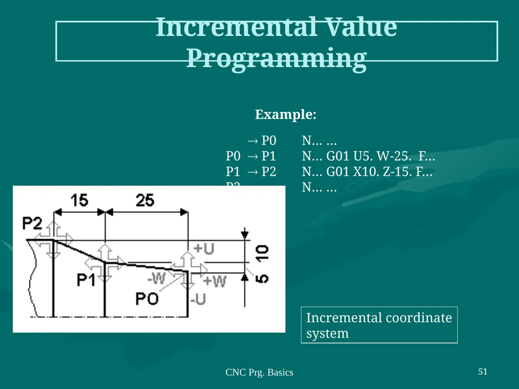
slide51. CNC Prg. Basics 51 Incremental Value Programming Incremental coordinate
system Example: P0 N… …
P0 P1 N… G01 U5. W-25. F…
P1 P2 N… G01 X10. Z-15. F…
P2 N… …<br>
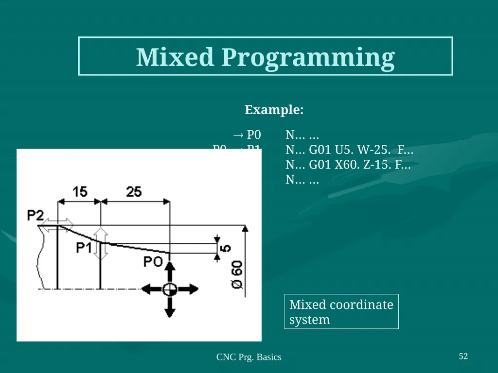
slide52. CNC Prg. Basics 52 Mixed Programming Mixed coordinate
system Example: P0 N… …
P0 P1 N… G01 U5. W-25. F…
P1 P2 N… G01 X60. Z-15. F…
P2 N… …<br>
slide53. CNC Prg. Basics 53 Self-holding Functions (1) The majority of G and M commands and other words are self-holding, remain active until overwritten or deactivated/deselected.
Aimed to simplify and to reduce programming tasks. Example: G41 can be deactivated by issuing G40 command.<br>
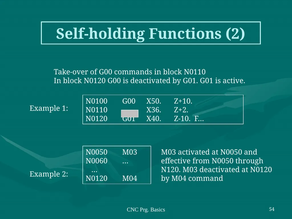
slide54. CNC Prg. Basics 54 Self-holding Functions (2) Take-over of G00 commands in block N0110
In block N0120 G00 is deactivated by G01. G01 is active. N0050 M03
N0060 …
…
N0120 M04 Example 1: Example 2: M03 activated at N0050 and effective from N0050 through N120. M03 deactivated at N0120 by M04 command<br>
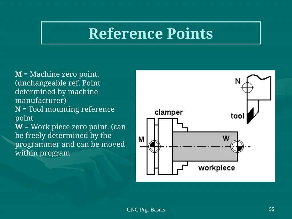
slide55. CNC Prg. Basics 55 Reference Points M = Machine zero point. (unchangeable ref. Point determined by machine manufacturer)
N = Tool mounting reference point
W = Work piece zero point. (can be freely determined by the programmer and can be moved within program<br>
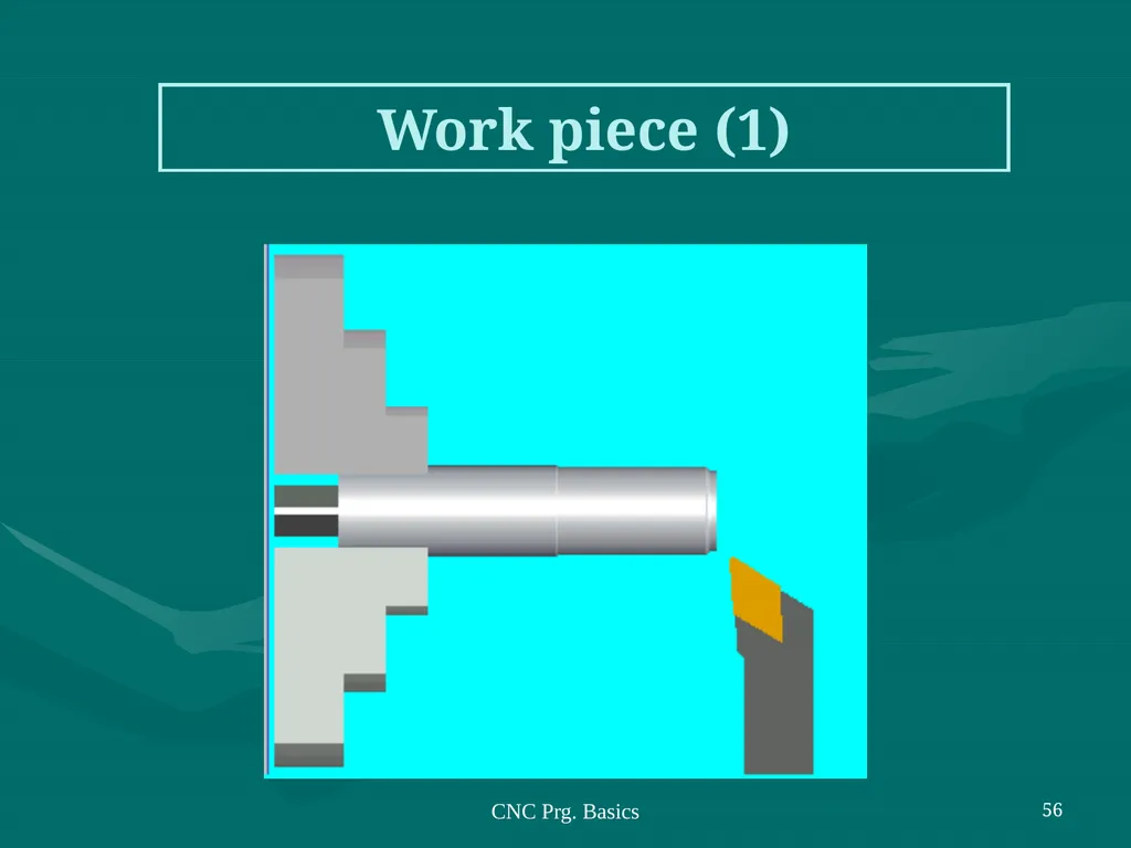
slide56. CNC Prg. Basics 56 Work piece (1)<br>
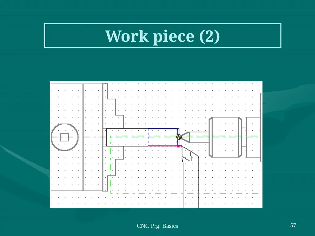
slide57. CNC Prg. Basics 57 Work piece (2)<br>
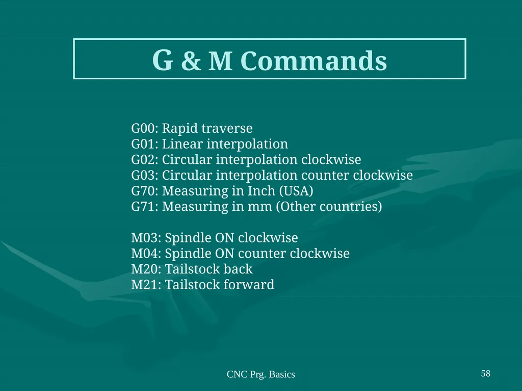
slide58. CNC Prg. Basics 58 G & M Commands G00: Rapid traverse
G01: Linear interpolation
G02: Circular interpolation clockwise
G03: Circular interpolation counter clockwise
G70: Measuring in Inch (USA)
G71: Measuring in mm (Other countries)
M03: Spindle ON clockwise
M04: Spindle ON counter clockwise
M20: Tailstock back
M21: Tailstock forward<br>
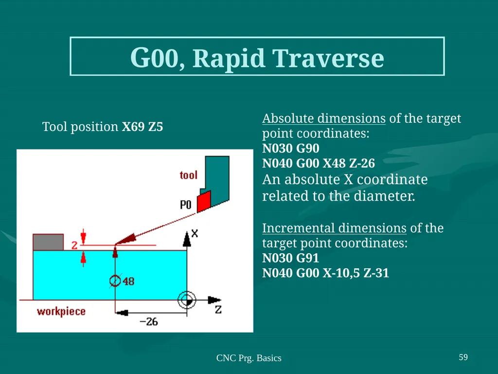
slide59. CNC Prg. Basics 59 G00, Rapid Traverse Absolute dimensions of the target point coordinates: N030 G90 N040 G00 X48 Z-26 An absolute X coordinate related to the diameter. Incremental dimensions of the target point coordinates: N030 G91 N040 G00 X-10,5 Z-31 Tool position X69 Z5<br>
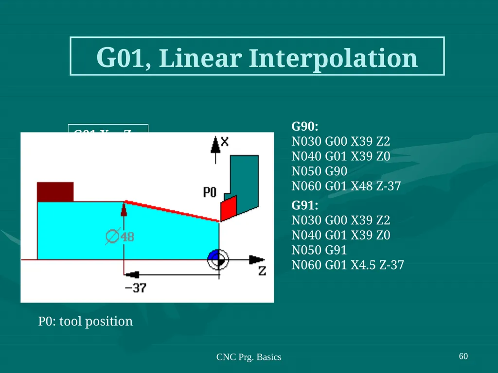
slide60. CNC Prg. Basics 60 G01, Linear Interpolation P0: tool position G90: N030 G00 X39 Z2 N040 G01 X39 Z0 N050 G90 N060 G01 X48 Z-37
G91: N030 G00 X39 Z2 N040 G01 X39 Z0 N050 G91 N060 G01 X4.5 Z-37 G01 X… Z…<br>
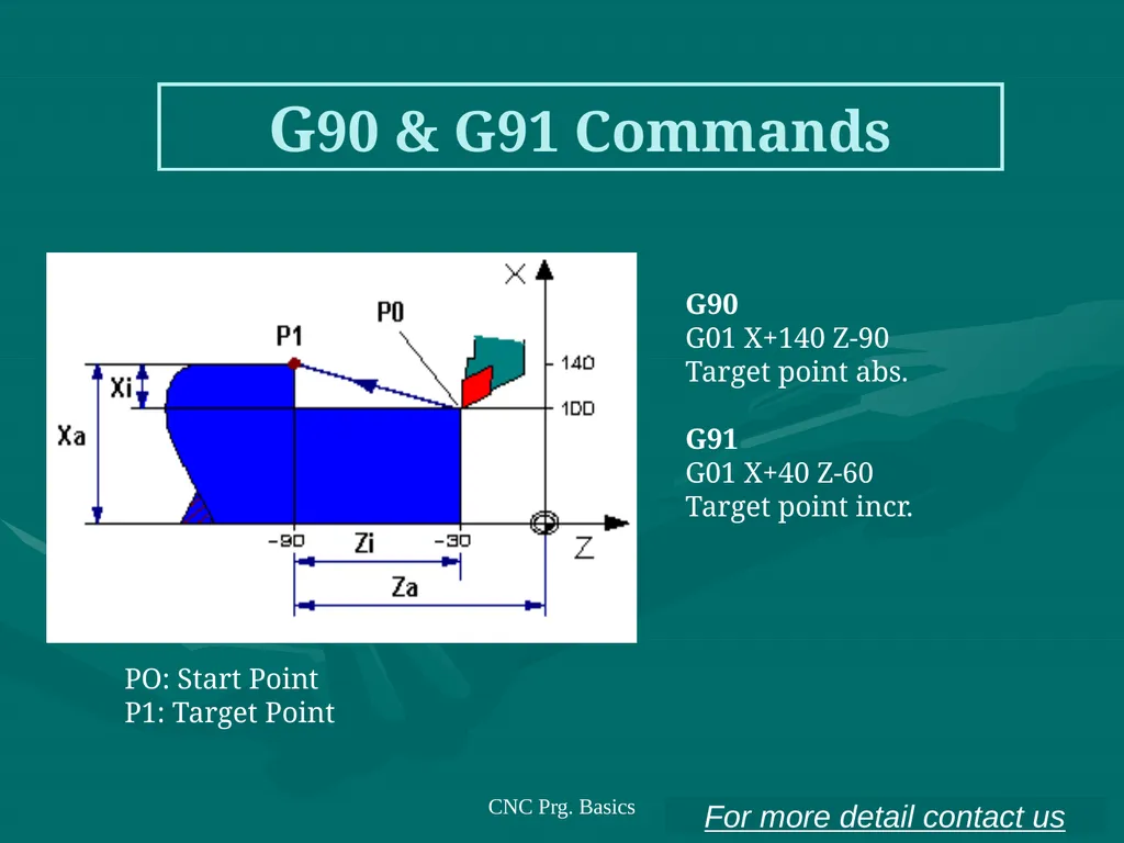
slide61. CNC Prg. Basics 61 G90 & G91 Commands G90 G01 X+140 Z-90 Target point abs. G91 G01 X+40 Z-60 Target point incr. PO: Start Point
P1: Target Point For more detail contact us<br>
slide2. PART PROGRAM A part program is a series of coded instructions required to produce a part. It controls the movement of the machine tool and the on/off control of auxiliary functions such as spindle rotation and coolant. The coded instructions are composed of letters, numbers and symbols and are arranged in a format of functional blocks as in the following example
N10 G01 X5.0 Y2.5 F15.0 | | | | | | | | | Feed rate (15 in/min) | | | Y-coordinate (2.5") | | X-coordinate (5.0") | Linear interpolation mode Sequence number<br>
slide3. PROGRAM INPUT DEVICE The program input device is the mechanism for part programs to be entered into the CNC control. The most commonly used program input devices are keyboards, punched tape reader, diskette drivers, throgh RS 232 serial ports and networks.<br>
slide4. MACHINE CONTROL UNIT The machine control unit (MCU) is the heart of a CNC system. It is used to perform the following functions:
Read coded instructions
Decode coded instructions
Implement interpolations (linear, circular, and helical) to generate axis motion commands
Feed axis motion commands to the amplifier circuits for driving the axis mechanisms
Receive the feedback signals of position and speed for each drive axis
Implement auxiliary control functions such as coolant or spindle on/off, and tool change<br>
slide5. CNC PROGRAMMING Offline programming linked to CAD programs.
Conversational programming by the operator.
MDI ~ Manual Data Input.
Manual Control using jog buttons or `electronic handwheel'.
Word-Address Coding using standard G-codes and M-codes.<br>
slide6. The position of the tool is described by using a Cartesian coordinate system. If (0,0,0) position can be described by the operator, then it is called floating zero.<br>
slide7. In defining the motion of the tool from one point to another, either absolute positioning mode or incremental positioning mode can be used.<br>
slide8. 1. Absolute positioning. In this mode, the desired target position of the tool for a particular move is given relative to the origin point of the program. 2. Incremental positioning. In this mode, the next target position for the tool is given relative to the current tool position.<br>
slide9. Structure of an NC Part Program: Commands are input into the controller in units called blocks or statements. Block Format: 1. Fixed sequential format
2. Tab sequential format
3. Word address format<br>
slide10. EXAMPLE: Assume that a drilling operation is to be programmed as: 1. The tool is positioned at (25.4,12.5,0) by a rapid movement.
2. The tool is then advanced -10 mm in the z direction at a feed rate of 500 mm/min., with the flood coolant on.
3.The is then retracted back 10 mm at the rapid feed rate, and the coolant is turned off.<br>
slide11. 1. Fixed sequential format 0050 00 +0025400 +0012500 +0000000 0000 00 0060 01 +0025400 +0012500 -0010000 0500 08 0070 00 +0025400 +0012500 +0000000 0000 09 2. Tab sequential format
0050 TAB 00 TAB +0025400 TAB +0012500 TAB +0000000 TAB
0060 TAB 01 TAB TAB TAB -0010000 TAB 0500 TAB 08
0070 TAB 00 TAB TAB TAB -0000000 TAB 0000 TAB 09 3. Word address format
N50 G00 X25400 Y125 Z0 F0
N60 G01 Z-10000 F500 M08
N70 G00 Z0 M09<br>
slide12. Modal commands: Commands issued in the NC program that will stay in effect until it is changed by some other command, like, feed rate selection, coolant selection, etc. Nonmodal commands: Commands that are effective only when issued and whose effects are lost for subsequent commands, like, a dwell command which instructs the tool to remain in a given configuration for a given amount of time.<br>
slide13. INFORMATION NEEDED by a CNC 1. Preparatory Information: units, incremental or absolute positioning
2. Coordinates: X,Y,Z, RX,RY,RZ
3. Machining Parameters: Feed rate and spindle speed
4. Coolant Control: On/Off, Flood, Mist
5. Tool Control: Tool and tool parameters
6. Cycle Functions: Type of action required
7. Miscellaneous Control: Spindle on/off, direction of rotation, stops for part movement
This information is conveyed to the machine through a set
of instructions arranged in a desired sequence – Program.<br>
slide14. BLOCK FORMAT Sample Block N135 G01 X1.0 Y1.0 Z0.125 F5
Restrictions on CNC blocks
Each may contain only one tool move
Each may contain any number of non-tool move G-codes
Each may contain only one feedrate
Each may contain only one specified tool or spindle speed
The block numbers should be sequential
Both the program start flag and the program number must be independent of all other commands (on separate lines)
The data within a block should follow the sequence shown in the above sample block<br>
slide15. WORD-ADDRESS CODING N5 G90 G20
N10 M06 T3
N15 M03 S1250
N20 G00 X1 Y1
N25 Z0.1
N30 G01 Z-0.125 F5
N35 X3 Y2 F10
N40 G00 Z1
N45 X0 Y0
N50 M05
N55 M30 Example CNC Program Each instruction to the machine consists of a letter followed by a number.
Each letter is associated with a specific type of action or piece of information needed by the machine. Letters used in Codes N,G,X,Y,Z,A,B,C,I,J,K,F,S,T,R,M<br>
slide16. G Codes G00 Rapid traverse
G01 Linear interpolation
G02 Circular interpolation, CW
G03 Circular interpolation, CCW
G04 Dwell
G08 Acceleration
G09 Deceleration
G17 X-Y Plane
G18 Z-X Plane
G19 Y-Z Plane
G20 Inch Units (G70)
G21 Metric Units (G71) G40 Cutter compensation – cancel
G41 Cutter compensation – left
G42 Cutter compensation- right
G70 Inch format
G71 Metric format
G74 Full-circle programming off
G75 Full-circle programming on
G80 Fixed-cycle cancel
G81-G89 Fixed cycles
G90 Absolute dimensions
G91 Incremental dimensions<br>
slide17. M Codes M00 Program stop
M01 Optional program stop
M02 Program end
M03 Spindle on clockwise
M04 Spindle on counterclockwise
M05 Spindle stop
M06 Tool change
M08 Coolant on
M09 Coolant off
M10 Clamps on
M11 Clamps off
M30 Program stop, reset to start<br>
slide18. N Codes Gives an identifying number for each block of information.
It is generally good practice to increment each block number by 5 or 10 to allow additional blocks to be inserted if future changes are required.<br>
slide19. X,Y, and Z Codes X, Y, and Z codes are used to specify the coordinate axis.
Number following the code defines the coordinate at the end of the move relative to an incremental or absolute reference point.<br>
slide20. I,J, and K Codes I, J, and K codes are used to specify the coordinate axis when defining the center of a circle.
Number following the code defines the respective coordinate for the center of the circle.<br>
slide21. F,S, and T Codes F-code: used to specify the feed rate
S-code: used to specify the spindle speed
T-code: used to specify the tool identification number associated with the tool to be used in subsequent operations.<br>
slide22. Application of Some Codes G01 Linear Interpolation Format: N_ G01 X_ Y_ Z_ F_
Linear Interpolation results in a straight line feed move.
Unless tool compensation is used, the coordinates are associated with the centerline of the tool.<br>
slide23. Application of Some Codes G01 Linear Interpolation . As an example, for the motion that occurs in x-y plane with the same maximum speed for the x- and y-axis, initial motion is at an angle of 45o to the axes until motion in one of
the axes is completed and then the balance of the motion occurs in the other axis. This is called point-to-point motion.<br>
slide24. Application of Some Codes G01 Linear Interpolation<br>
slide25. N10 G00 X1 Z1 N15 Z0.1 N20 G01 Z-0.125 F5 N25 X2 Z2 F10 G01 Linear Interpolation X Z<br>
slide26. G02 Circular Interpolation G02 is also a preparatory function to specify that the tool should be moved to a specified location along a circular path in a clockwise direction. In order to specify the path to the MCU, the end point of the arc and the location of the center of the arc should be specified. Within the block in which the G02 code is programmed, the center of the arc is given by specifying its location relative to the start of the arc.<br>
slide27. G02 Circular Interpolation (CW) The G02 command requires an endpoint and a radius in order to cut the arc.
I,J, and K are relative to the start point.
N_ G02 X2 Y1 I0 J-1 F10
or
N_ G02 X2 Y1 R1<br>
slide28. G02 Circular Interpolation (CW)<br>
slide29. The sequence of some machining operations is may be the same for any part and for any machine. For example, drilling a hole involves the following steps:
Position the tool above the point where the hole will be drilled
Set the correct spindle speed
Feed the tool into the workpiece at a controlled feed rate to a predetermined depth
Retract the tool at a rapid rate to just above the point where the hole started Canned Cycles<br>
slide31. G81 ILLUSTRATION<br>
slide32. Three Main parts of a CNC program N5 G90 G21 (Absolute units, metric)
N10 M06 T2 (Stop for tool change, use tool # 2)
N15 M03 S1200 (Turn the spindle on CW to 1200 rpm) Part 1- Program Petup<br>
slide33. Three Main parts of a CNC program N20 G00 X1 Y1 (Rapid to X1,Y1 from origin point)
N25 Z0.125 (Rapid down to Z0.125)
N30 G01 Z-0.125 F100 (Feed down to Z-0.125 at 100 mm/min)
N35 G01 X2 Y2 (Feed diagonally to X2,Y2)
N40 G00 Z1 (Rapid up to Z1)
N45 X0 Y0 (Rapid to X0,Y0) Part 2- Chip Removal<br>
slide34. Three Main parts of a CNC program N50 M05 (Turn the spindle off)
N55 M00 (Program stop) Part 3- System Shutdown<br>
slide35. EXAMPLE OPERATION on CNC MILLING MACHINE<br>
slide36. G-CODE PROGRAM First pass : conventional mill to a depth of 0.125 around edge profile. Tool 1 is a ½ inch dia. end mill.
%
:1002
N5 G90 G20
N10 M06 T1
N15 M03 S1200
N20 G00 X0.125 Y0.125
N30 Z0.125
N35 G01 Z-0.125 F5
N40 X3.875
N45 Y4.125
N50 X0.125
N55 Y0.125<br>
slide37. Second pass: conventional mill to a depth of 0.25 around edge profile.
N35 Z-0.250
N40 X3.875
N45 Y4.125
N50 X0.125
N55 Y0.125
N60 Z0.125<br>
slide38. Third pass: conventional mill to a depth of 0.125 around pocket profile.
N65 G00 X1.25 Y1.0
N70 G01 Z-0.125 F5
N75 X1.75
N80 Y2.5
N85 X1.25
N90 Y1.0
N95 Z0.125<br>
slide39. Fourth pass: climb mill to a depth of 0.125 across remaining material.
N100 Y2.125
N105 X2.625
N110 Z0.125
N115 G00 X-5 Y-5 Z5
N120 M05
N125 M30<br>
slide40. Advanced features:
Execution of the part of the program in a rotated or mirrored position.
Ability to scale the program and produce larger or smaller programs.
Three dimensional circular interpolation which produces a helical shape.
Parabolic and cubic interpolation.<br>
slide41. NC program preparation may be tedious and difficult if the part to be machined has a complex geometry. The main difficulty is to find out the cutter locations during the machining. Computers may be used to assist the programmers in preparing the NC codes. Computer Aided Part Programming:<br>
slide42. Advantages of applying computer-aided part programming include the following:
1. It reduces the manual calculations involves in determining the geometric characteristics of the part.
It provides the cutter path simulation.
It provides tool collision checking.
It shortens the program preparation time.
It makes the program preparation easier.<br>
slide43. The Aerospace Industries Association sponsored the work that led to the first part programming language, developed in MIT in 1955.
This was called: Automatically Programmed Tools (APT).
APT is an English like simple programming language which basically produce the Cutter Location (CL) data.
Using the cutter location data, the program can generate the actual NC codes by using a postprocessor .<br>
slide44. The output of any CAD package include the geometric data of the part to be machined. Therefore, many CAD/CAM package can produce cutter location (CL) data to be used for NC code generation.
There is still to be a process planning module for a workable NC code generation.
Some of the CAD/CAM packages that have the NC code generation capabilities are Computervision, CATIA, CADAM, ProEngineer, MechanicalDesktop (Auto Desk). CAD/CAM Based Part Programming:<br>
slide45. CNC Prg. Basics 45 CNC Programming Basics Program structure
Every program consists of:
Program Start The program start is the program number. The program number begins with character/letter O.
Program Contents NC blocks
Program End M30 for a main program M17 for a sub-program<br>
slide46. CNC Prg. Basics 46 CNC Program Numbers Program Numbers
O6999
.
.
.
O0256
O0255
.
.
.
O0000<br>
slide47. CNC Prg. Basics 47 CNC Program Blocks (1) N is the address
Block numbers from N0000 to
N9999
A block consists of number and words
Words are contents of a block
Block numbers are selected in the jumps of ten for the purpose of insertion<br>
slide48. CNC Prg. Basics 48 CNC Program Blocks (2) A block consists of one or more blocks
A Word consists of a character (address) and a number.
Every address has a certain meaning, on which the corresponding number depends<br>
slide49. CNC Prg. Basics 49 CNC Prg. Syntax Regulations The maximum block length must not exceeded four lines. If max. length exceeded alarm 650 occurs.
Every block starts with a block number.
After the block numbers follows the G command.
Words consists of coordinates X(U), Z(W).
For G02, G03 program interpolation parameter I and K are placed after X(U), Z(W).
The F word (feed, thread pitch).
The S word (cutting speed).
The T word (tool address).
The M word (additional functions).<br>
slide50. CNC Prg. Basics 50 Absolute Value Programming P0 N… …
P0 P1 N… G01 X40. Z25. F…
P1 P2 N… G01 X60. Z-40. F…
P2 N… … Absolute coordinate
system Example:<br>
slide51. CNC Prg. Basics 51 Incremental Value Programming Incremental coordinate
system Example: P0 N… …
P0 P1 N… G01 U5. W-25. F…
P1 P2 N… G01 X10. Z-15. F…
P2 N… …<br>
slide52. CNC Prg. Basics 52 Mixed Programming Mixed coordinate
system Example: P0 N… …
P0 P1 N… G01 U5. W-25. F…
P1 P2 N… G01 X60. Z-15. F…
P2 N… …<br>
slide53. CNC Prg. Basics 53 Self-holding Functions (1) The majority of G and M commands and other words are self-holding, remain active until overwritten or deactivated/deselected.
Aimed to simplify and to reduce programming tasks. Example: G41 can be deactivated by issuing G40 command.<br>
slide54. CNC Prg. Basics 54 Self-holding Functions (2) Take-over of G00 commands in block N0110
In block N0120 G00 is deactivated by G01. G01 is active. N0050 M03
N0060 …
…
N0120 M04 Example 1: Example 2: M03 activated at N0050 and effective from N0050 through N120. M03 deactivated at N0120 by M04 command<br>
slide55. CNC Prg. Basics 55 Reference Points M = Machine zero point. (unchangeable ref. Point determined by machine manufacturer)
N = Tool mounting reference point
W = Work piece zero point. (can be freely determined by the programmer and can be moved within program<br>
slide56. CNC Prg. Basics 56 Work piece (1)<br>
slide57. CNC Prg. Basics 57 Work piece (2)<br>
slide58. CNC Prg. Basics 58 G & M Commands G00: Rapid traverse
G01: Linear interpolation
G02: Circular interpolation clockwise
G03: Circular interpolation counter clockwise
G70: Measuring in Inch (USA)
G71: Measuring in mm (Other countries)
M03: Spindle ON clockwise
M04: Spindle ON counter clockwise
M20: Tailstock back
M21: Tailstock forward<br>
slide59. CNC Prg. Basics 59 G00, Rapid Traverse Absolute dimensions of the target point coordinates: N030 G90 N040 G00 X48 Z-26 An absolute X coordinate related to the diameter. Incremental dimensions of the target point coordinates: N030 G91 N040 G00 X-10,5 Z-31 Tool position X69 Z5<br>
slide60. CNC Prg. Basics 60 G01, Linear Interpolation P0: tool position G90: N030 G00 X39 Z2 N040 G01 X39 Z0 N050 G90 N060 G01 X48 Z-37
G91: N030 G00 X39 Z2 N040 G01 X39 Z0 N050 G91 N060 G01 X4.5 Z-37 G01 X… Z…<br>
slide61. CNC Prg. Basics 61 G90 & G91 Commands G90 G01 X+140 Z-90 Target point abs. G91 G01 X+40 Z-60 Target point incr. PO: Start Point
P1: Target Point For more detail contact us<br>