
8 Gas Tungsten Arc Welding Chapter Contrast the



Description: 8 Gas Tungsten Arc Welding Chapter Contrast the effects of DCEN, DCEP, and ac on surface cleaning efficiency, electrode life, and weld characteristics. Select the proper welding power source, polarity, shielding gas, flow rate, tungsten
Related Topics
Download Presentation
"8 Gas Tungsten Arc Welding Chapter Contrast the" is the property of its rightful owner. Permission is granted to download and print the materials on this website for personal, non-commercial use only, and to display it on your personal computer provided you do not modify the materials and that you retain all copyright notices contained in the materials. By downloading content from our website, you accept the terms of this agreement.
Presentation Transcript
slide2. 8 Gas Tungsten Arc Welding Chapter<br>
slide3. Contrast the effects of DCEN, DCEP, and ac on surface cleaning efficiency, electrode life, and weld characteristics.
Select the proper welding power source, polarity, shielding gas, flow rate, tungsten electrode type and diameter, nozzle size, and filler metal required to produce an acceptable weld using the GTAW process.
Properly assemble the parts of a GTAW welding station and GTAW torch.
Correctly prepare a tungsten electrode for welding with an ac or dc power source.<br>
slide4. Correctly prepare metals for welding and create acceptable welds on all types of joints in all positions.
Correctly set and adjust the welding current and shielding gas flow rate.
Weld different base metals using GTAW process.
Identify the potential safety hazards of using the GTAW process in a working environment and describe ways of safely dealing with these hazards.
Pass a safety test on the proper and safe use of the GTAW process.<br>
slide5. Gas Tungsten Arc Welding Gas tungsten arc welding (GTAW) is a process used to produce high-quality welds on virtually all weldable metals
GTAW is done with a tungsten electrode
The tungsten electrode is not consumed
GTAW can be done in any position
Filler metal may or may not be required with GTAW<br>
slide6. Gas Tungsten Arc Welding Principles Either direct current electrode negative (DCEN) or direct current electrode positive (DCEP) can be used
Filler metal is added to the weld pool either manually or automatically
Manual welding with an automatic wire feeder is called semiautomatic welding<br>
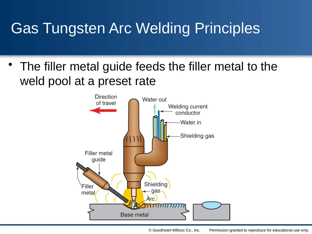
slide7. Gas Tungsten Arc Welding Principles The filler metal guide feeds the filler metal to the weld pool at a preset rate<br>
slide8. Gas Tungsten Arc Welding Principles Alternating current or DCEP is used when surface oxides must be removed
Metal oxides, known as refractory oxides, melt at a higher temperature than the base metal
Ac gives better penetration than DCEP
Welding with DCEP current requires an electrode larger than one used for ac welding<br>
slide9. Pulsed DC GTAW Welding When dc current is used, it can be electronically controlled to create a pulsed arc
A pulsed arc provides a period of high welding current and a period of lower current
The high current is called peak current
The low current is called background current
Not all gas tungsten arc welding machines can provide a pulsed current<br>
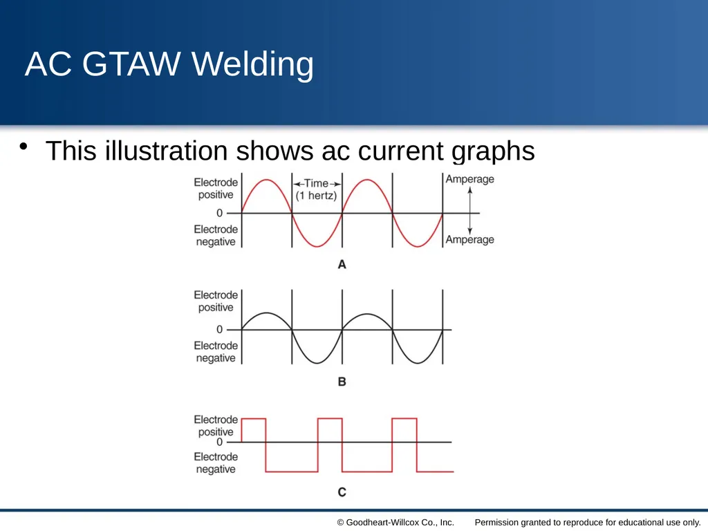
slide10. AC GTAW Welding The graph of a normal ac current flow is called a sine wave
Ac current can be controlled to provide a desired amperage or polarity
More electrode negative time or more current will provide for better penetration
By adjusting the wave pattern, a welder can create a welding current to suit the job<br>
slide11. AC GTAW Welding This illustration shows ac current graphs<br>
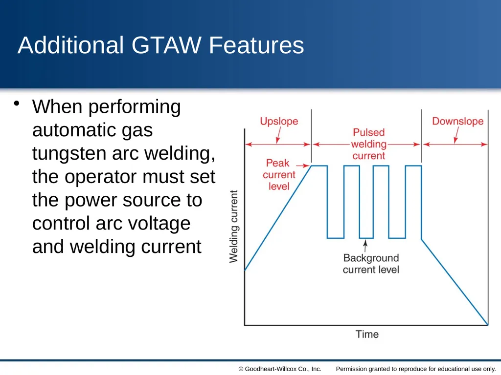
slide12. Additional GTAW Features Upslope current is used at the beginning of a weld to gradually increase the current from zero to the welding current
Downslope current is a gradual decrease in current at the end of the weld
Pulsed current is used with good results when the workpieces do not fit together well<br>
slide13. Additional GTAW Features When performing automatic gas tungsten arc welding, the operator must set the power source to control arc voltage and welding current<br>
slide14. GTAW Power Sources Welding power sources for GTAW must provide a constant welding current
Most GTAW machines provide both ac and dc current
Shielding gas made to flow before the arc is struck is called preflow
Shielding gas that continues to flow after the arc is stopped is called postflow<br>
slide15. Setting Up a GTAW Station The arc welding power source should be given a brief safety inspection prior to use
The ground leap clamp should be checked for a good connection
Check to make sure the shielding gas cylinder is properly secured
Connect the fittings from the torch to the proper locations on the welding machine<br>
slide16. A chain or other safety device should be used to prevent a gas cylinder from being knocked over Safety<br>
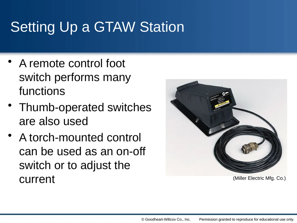
slide17. Setting Up a GTAW Station A remote control foot switch performs many functions
Thumb-operated switches are also used
A torch-mounted control can be used as an on-off switch or to adjust the current (Miller Electric Mfg. Co.)<br>
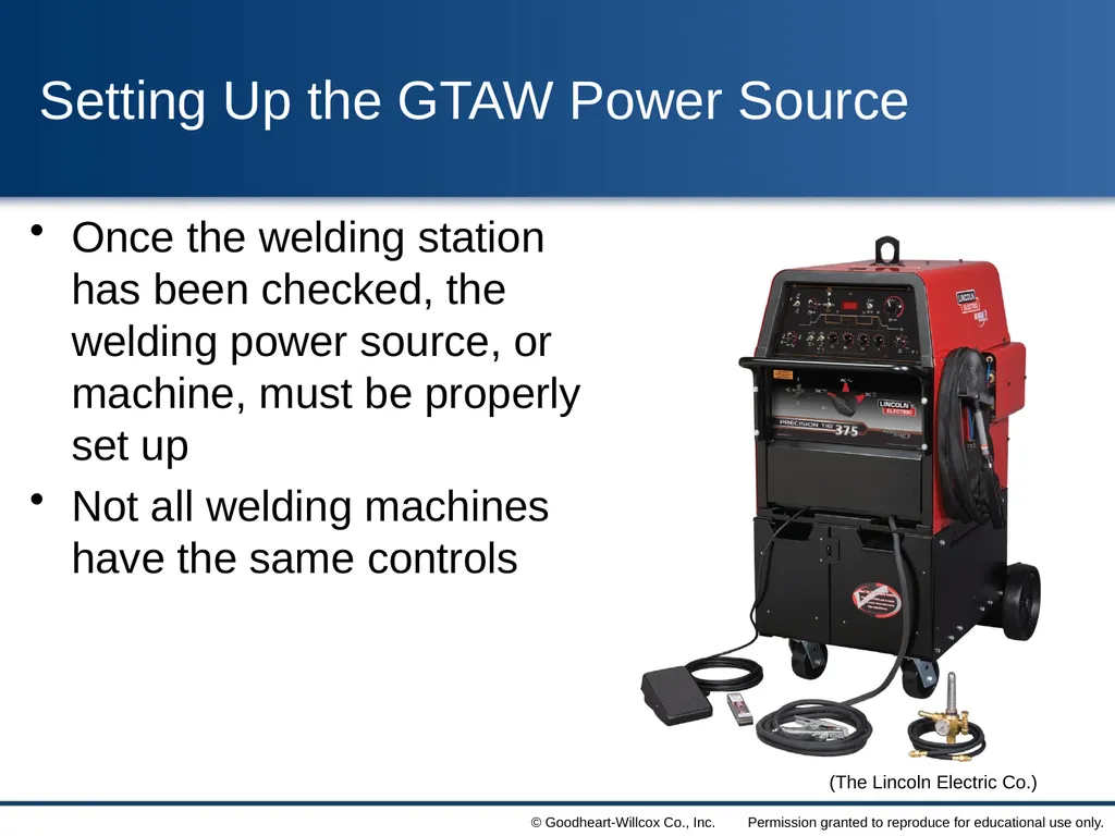
slide18. Setting Up the GTAW Power Source Once the welding station has been checked, the welding power source, or machine, must be properly set up
Not all welding machines have the same controls (The Lincoln Electric Co.)<br>
slide19. Selecting the Proper Current for GTAW When selecting the type of current to use for a welding job, usually the most important factor is the type of base metal to be welded
Alternating current combines the penetration and cleaning qualities of DCEN and DCEP
After the type of current is selected, the amount of current must be set<br>
slide20. Proper Shielding Gas for GTAW Argon is the most common shielding gas used for ac and dc GTAW
Using argon provides a smoother arc
Helium provides a higher available heat at the workpiece
Argon and helium mixtures are used in some applications
Gas mixtures can be obtained in cylinders from distributors
Gas mixtures can also be created using a gas mixer<br>
slide21. Selecting the Correct Gas Flow Rate The flow rate is the volume of gas flowing
This flow rate varies with
The base metal being welded
The thickness of the base metal
The position of the welded joint
After the correct gas and flow rate are determined, the rate must be set on the flowmeter<br>
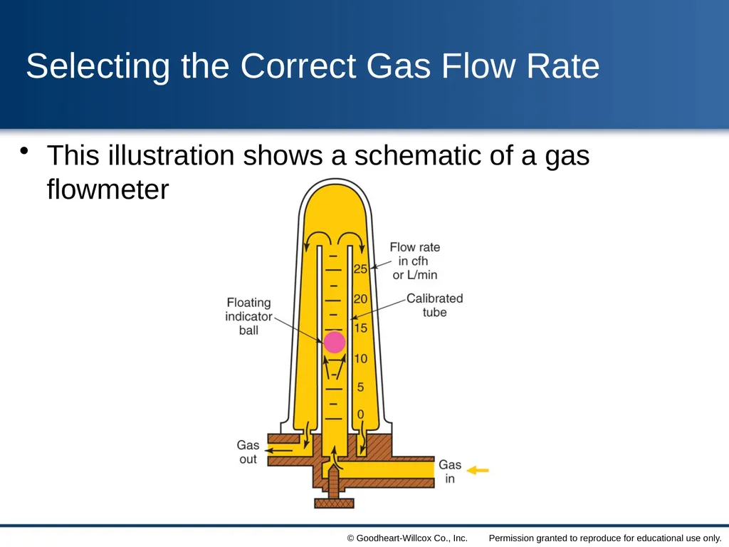
slide22. Selecting the Correct Gas Flow Rate This illustration shows a schematic of a gas flowmeter<br>
slide23. Tungsten Electrodes for GTAW The selection of the correct tungsten electrode is very important
Determine the type and thickness of metal to be welded
Select the correct electrode by type and diameter
For ac welding, pure tungsten or zirconiated electrodes are preferred<br>
slide24. Tungsten Electrodes for GTAW Dc welding is usually done with thoriated tungsten electrodes
Electrodes with ceria and lanthana added can be used for ac and dc welding
Tungsten electrodes of any type must be protected from contamination
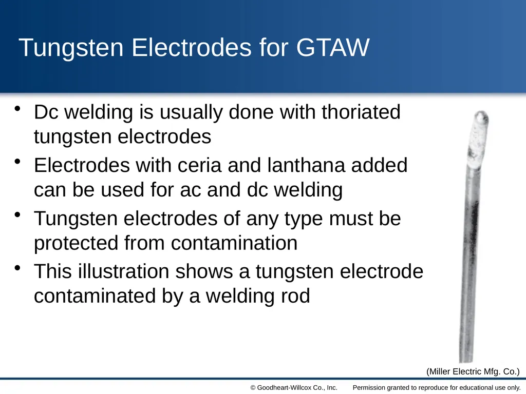
This illustration shows a tungsten electrode contaminated by a welding rod (Miller Electric Mfg. Co.)<br>
slide25. Tungsten Electrodes for GTAW Contamination may be from oxygen and nitrogen in the air and from airborne dirt
Tungsten electrodes come in sizes from 0.010″ to 1/4″
Special grinding wheels should be used for pointing tungsten electrodes
Grinding wheels made of borazon or diamond are preferred<br>
slide26. Tungsten dust should not be inhaled
Thoriated tungsten contains thorium, a low level radioactive material
A dust extractor should be installed on the grinding wheel to control dust
A dust mask can be worn
Always wear safety glasses or goggles when grinding Safety<br>
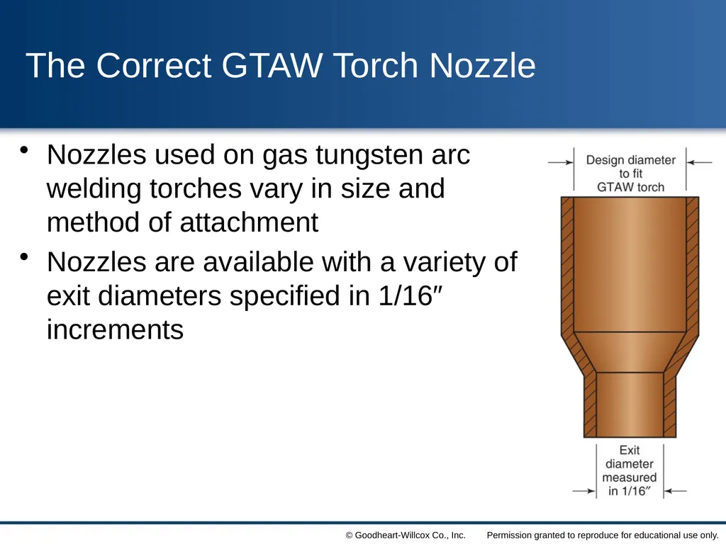
slide27. The Correct GTAW Torch Nozzle Nozzles used on gas tungsten arc welding torches vary in size and method of attachment
Nozzles are available with a variety of exit diameters specified in 1/16″ increments<br>
slide28. The Correct Filler Metal for GTAW Filler metal used for GTAW is generally bare, uncoated, wire
The filler metal is purchased in large coils or in precut lengths
Filler metal alloy must be selected for the specific job
Common diameters of filler wires vary from 1/16″ to 1/4″<br>
slide29. Preparing Metal for Welding Before welding, the surface of the base metal must be thoroughly cleaned
The joint designs used for GTAW are the same as those used for SMAW
If parts must be beveled or shaped, they may be cut by thermal or mechanical means
Metal parts of a weldment must be held in alignment for welding<br>
slide30. Preparing Metal for Welding A backing ring or strip can be used when welding metals exhibit hot shortness
Shielding gas applied to the root side of a weld is often called backing gas
To prevent contamination, parts can be welded in a chamber
The chamber may contain shielding gas, or it may be a vacuum<br>
slide31. Always wear goggles to protect your eyes when using chemical solutions or wire brushes
Never enter an area filled with a shielding gas unless you are wearing an air-supplied respirator
In a space filled with shielding gas, a person can lose consciousness or die
Using an air-purifying respirator in a room with no oxygen will result in death Safety<br>
slide32. Methods for Starting the Arc A gas tungsten arc can be started in one of three ways
When touch starting is used, the electrode is touched to the base metal and then withdrawn
With superimposed high frequency, the nozzle is placed on the metal and the contactor switch is turned on
High-voltage starting is done with a high-voltage surge<br>
slide33. Gas Tungsten Arc Welding Techniques Position the torch at or near the start of the weld and strike the arc
Move to the location where the base metal must be melted
When the weld pool reaches the desired size, add welding rod if needed
Start moving the weld pool along the joint<br>
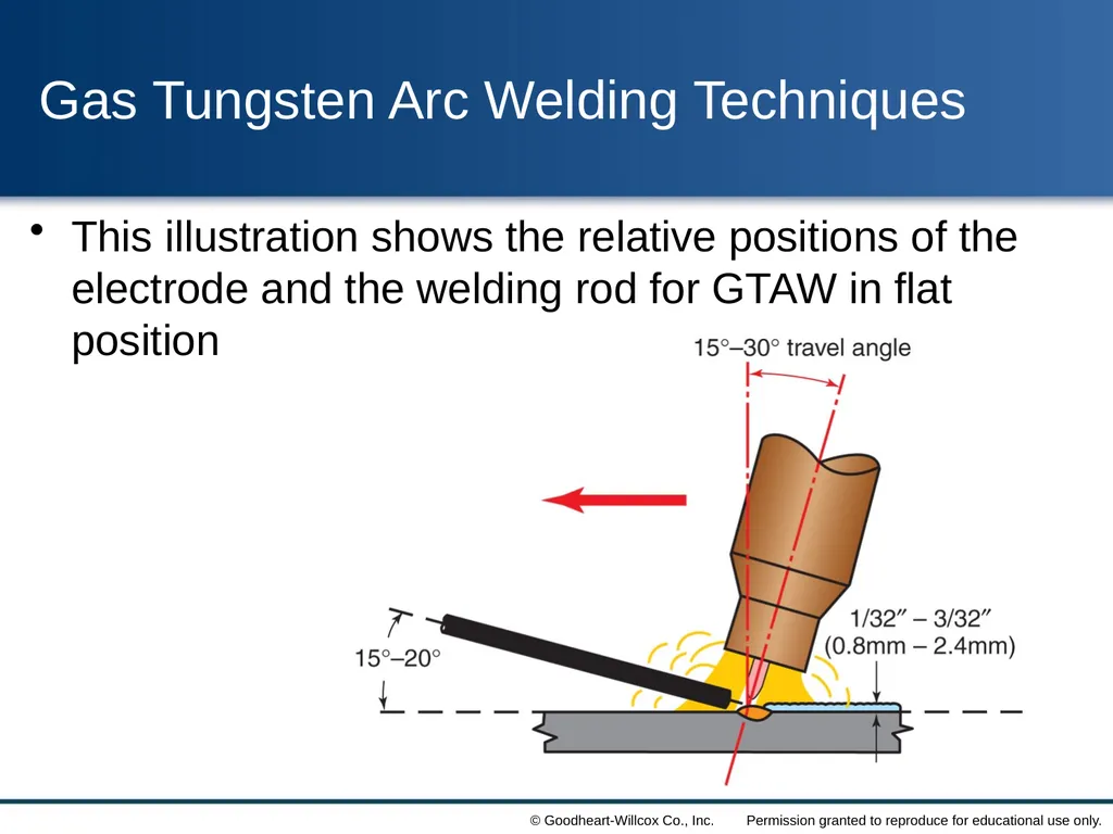
slide34. Gas Tungsten Arc Welding Techniques This illustration shows the relative positions of the electrode and the welding rod for GTAW in flat position<br>
slide35. Gas Tungsten Arc Welding Techniques While welding, control the location of the arc and the arc length
Add filler metal at the proper times
The welding current may be changed while welding
GTAW requires practice to master<br>
slide36. Shutting Down the GTAW Station When welding is stopped for long periods, the station should be shut down
After the gas postflow period, hang up the torch
Shut off the shielding gas cylinder
Drain the shielding gas system of gas
Turn off the regulator and flowmeter
Turn off the arc welding power source switch<br>
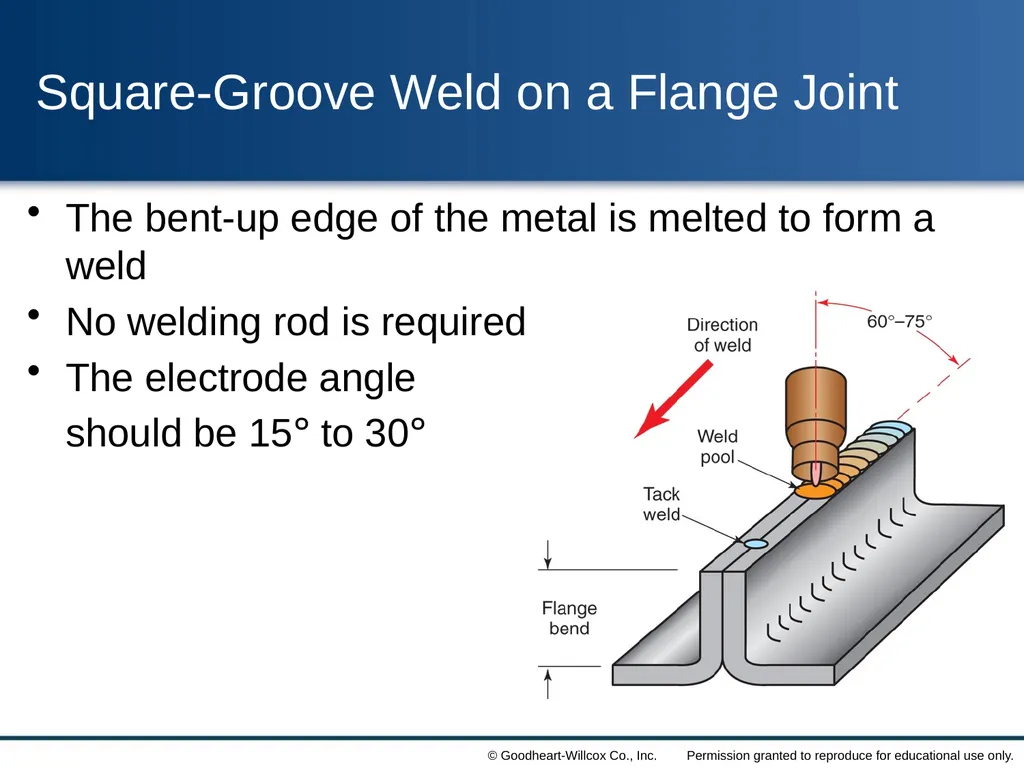
slide37. Square-Groove Weld on a Flange Joint The bent-up edge of the metal is melted to form a weld
No welding rod is required
The electrode angle
should be 15° to 30°<br>
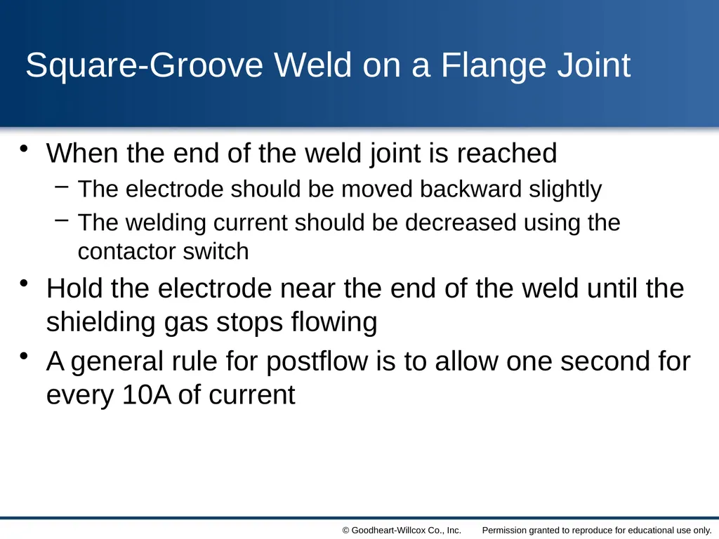
slide38. Square-Groove Weld on a Flange Joint When the end of the weld joint is reached
The electrode should be moved backward slightly
The welding current should be decreased using the contactor switch
Hold the electrode near the end of the weld until the shielding gas stops flowing
A general rule for postflow is to allow one second for every 10A of current<br>
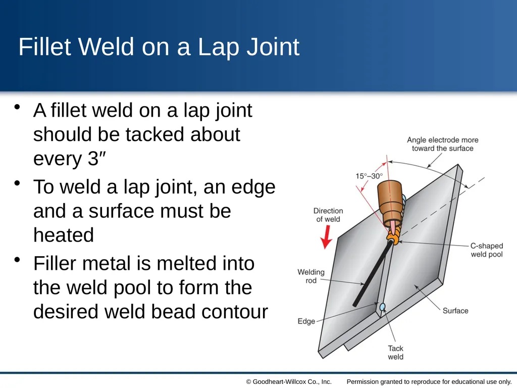
slide39. Fillet Weld on a Lap Joint A fillet weld on a lap joint should be tacked about every 3″
To weld a lap joint, an edge and a surface must be heated
Filler metal is melted into the weld pool to form the desired weld bead contour<br>
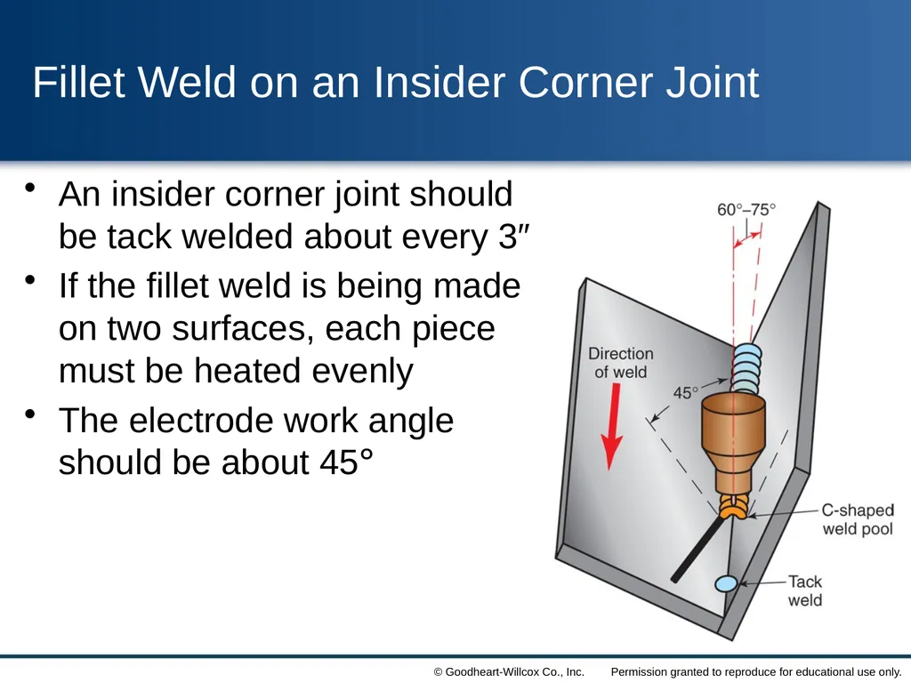
slide40. Fillet Weld on an Insider Corner Joint An insider corner joint should be tack welded about every 3″
If the fillet weld is being made on two surfaces, each piece must be heated evenly
The electrode work angle should be about 45°<br>
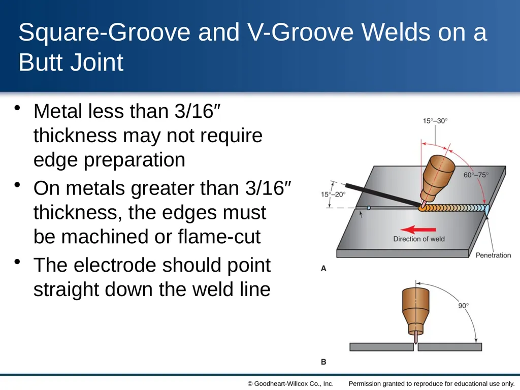
slide41. Square-Groove and V-Groove Welds on a Butt Joint Metal less than 3/16″ thickness may not require edge preparation
On metals greater than 3/16″ thickness, the edges must be machined or flame-cut
The electrode should point straight down the weld line<br>
slide42. Square-Groove and V-Groove Welds on a Butt Joint The design shapes may be square-, U-, J-, V-, or bevel-groove
To obtain complete penetration, the keyhole method of welding is used
To complete a V-groove or other wide-mouthed joint, a weaving bead might be used<br>
slide43. Welding Joints in Horizontal Position When horizontal welding is done, the weld line is horizontal and the face of the bead is in a near-vertical position
To prevent the downward flow of weld metal
Keep the weld pool small
Add the welding rod to the upper edge of the pool
Point the electrode slightly upward<br>
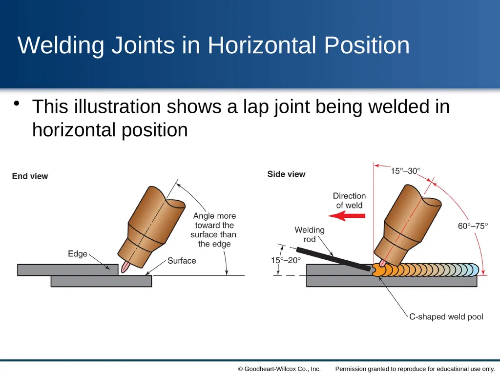
slide44. Welding Joints in Horizontal Position This illustration shows a lap joint being welded in horizontal position<br>
slide45. Welding Joints in Vertical Position When welding vertically, it is important to use the lowest current possible for a good weld
A pulsed arc may be used to provide a good cooling period that helps control the molten pool
Vertical welds may be made uphill or downhill<br>
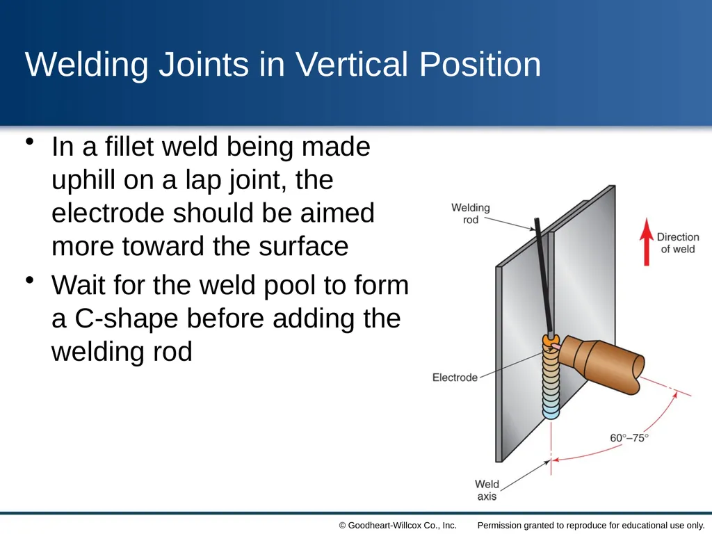
slide46. Welding Joints in Vertical Position In a fillet weld being made uphill on a lap joint, the electrode should be aimed more toward the surface
Wait for the weld pool to form a C-shape before adding the welding rod<br>
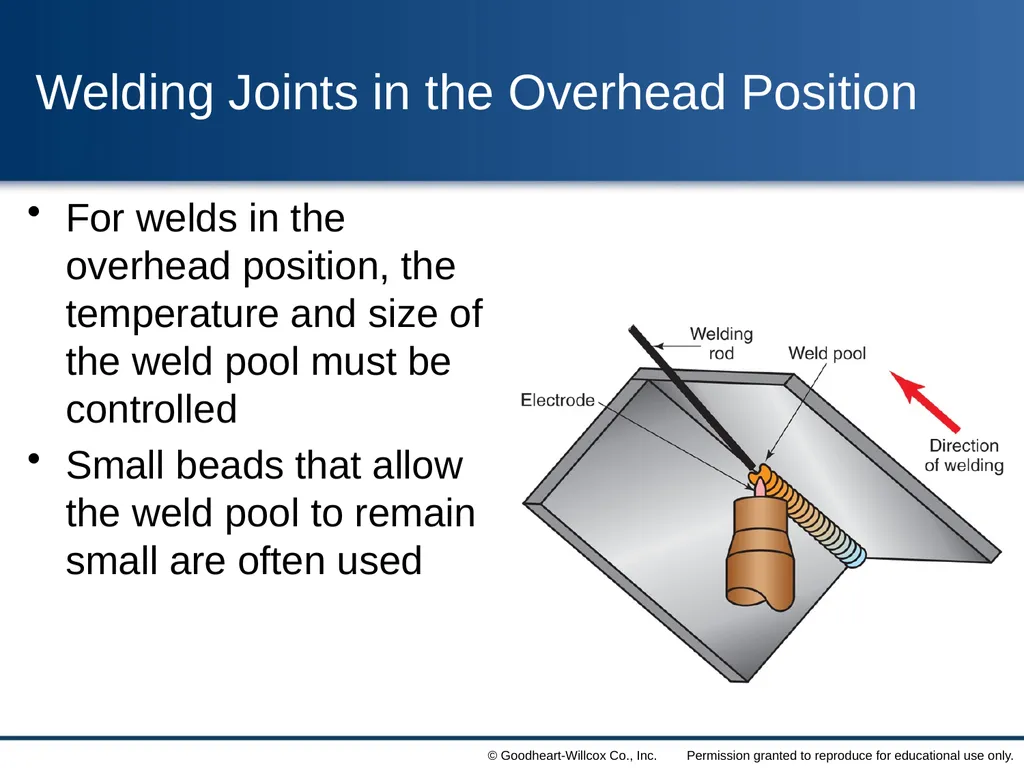
slide47. Welding Joints in the Overhead Position For welds in the overhead position, the temperature and size of the weld pool must be controlled
Small beads that allow the weld pool to remain small are often used Insert figure 8-62<br>
slide48. Semiautomatic Welding Semiautomatic GTAW is very similar to manual GTAW
The wire feed mechanism must have
A wire drive device
A speed control
An attachment to the torch that guides the wire into the weld pool
The welder must control the arc length and travel speed<br>
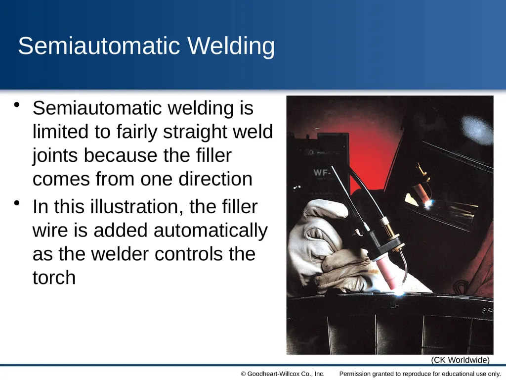
slide49. Semiautomatic Welding Semiautomatic welding is limited to fairly straight weld joints because the filler comes from one direction
In this illustration, the filler wire is added automatically as the welder controls the torch (CK Worldwide)<br>
slide50. Automated and Mechanized GTAW Gas tungsten arc welding can be mechanized or fully automated
An automatic GTAW system uses feedback signals to adjust the process to maintain a high-quality weld
Mechanized GTAW does not have feedback systems<br>
slide51. Automated and Mechanized GTAW One method used is to mount the torch to a track or a beam and move it along the weld joint
Another option is to keep the torch in place and move the part
A robot can be programmed to use the GTAW process to weld a complete, complex assembly<br>
slide52. Automated and Mechanized GTAW Automatic and mechanized GTAW produce welds with excellent quality
Automatic GTAW may be done in all positions using pulsed arc
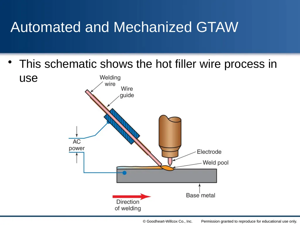
To increase the rate of welding, a hot filler wire process is sometimes used
Heating the welding wire saves much of the heat of the arc for melting the base metal<br>
slide53. Automated and Mechanized GTAW This schematic shows the hot filler wire process in use<br>
slide54. GTAW Spot Welding Gas tungsten arc welding can be used to produce spot welds
The process consists of striking an arc and holding it in one place
The top sheet of metal melts and fuses with a molten portion of the material below
When spot welding is done with GTAW, the welding process is automatically controlled<br>
slide55. GTAW Troubleshooting Guide Problems can affect the quality of a completed weld
An unstable arc
Rapid electrode consumption
Tungsten in the weld
Porous welds
Welders should watch for these problems and take steps to correct them<br>
slide56. GTAW Safety All safety precautions required for other arc welding processes apply to GTAW
Welders should wear protective clothing
GTAW creates ultraviolet and infrared radiation that can cause burns
Gloves are required to protect the hands
Filter shades are recommended for GTAW
Adequate ventilation must be provided<br>
slide57. Inert gases, CO, and CO2 displace oxygen in confined spaces
Wear an air-supplied respirator when entering a space filled with an inert gas, CO, or CO2 Safety<br>
slide3. Contrast the effects of DCEN, DCEP, and ac on surface cleaning efficiency, electrode life, and weld characteristics.
Select the proper welding power source, polarity, shielding gas, flow rate, tungsten electrode type and diameter, nozzle size, and filler metal required to produce an acceptable weld using the GTAW process.
Properly assemble the parts of a GTAW welding station and GTAW torch.
Correctly prepare a tungsten electrode for welding with an ac or dc power source.<br>
slide4. Correctly prepare metals for welding and create acceptable welds on all types of joints in all positions.
Correctly set and adjust the welding current and shielding gas flow rate.
Weld different base metals using GTAW process.
Identify the potential safety hazards of using the GTAW process in a working environment and describe ways of safely dealing with these hazards.
Pass a safety test on the proper and safe use of the GTAW process.<br>
slide5. Gas Tungsten Arc Welding Gas tungsten arc welding (GTAW) is a process used to produce high-quality welds on virtually all weldable metals
GTAW is done with a tungsten electrode
The tungsten electrode is not consumed
GTAW can be done in any position
Filler metal may or may not be required with GTAW<br>
slide6. Gas Tungsten Arc Welding Principles Either direct current electrode negative (DCEN) or direct current electrode positive (DCEP) can be used
Filler metal is added to the weld pool either manually or automatically
Manual welding with an automatic wire feeder is called semiautomatic welding<br>
slide7. Gas Tungsten Arc Welding Principles The filler metal guide feeds the filler metal to the weld pool at a preset rate<br>
slide8. Gas Tungsten Arc Welding Principles Alternating current or DCEP is used when surface oxides must be removed
Metal oxides, known as refractory oxides, melt at a higher temperature than the base metal
Ac gives better penetration than DCEP
Welding with DCEP current requires an electrode larger than one used for ac welding<br>
slide9. Pulsed DC GTAW Welding When dc current is used, it can be electronically controlled to create a pulsed arc
A pulsed arc provides a period of high welding current and a period of lower current
The high current is called peak current
The low current is called background current
Not all gas tungsten arc welding machines can provide a pulsed current<br>
slide10. AC GTAW Welding The graph of a normal ac current flow is called a sine wave
Ac current can be controlled to provide a desired amperage or polarity
More electrode negative time or more current will provide for better penetration
By adjusting the wave pattern, a welder can create a welding current to suit the job<br>
slide11. AC GTAW Welding This illustration shows ac current graphs<br>
slide12. Additional GTAW Features Upslope current is used at the beginning of a weld to gradually increase the current from zero to the welding current
Downslope current is a gradual decrease in current at the end of the weld
Pulsed current is used with good results when the workpieces do not fit together well<br>
slide13. Additional GTAW Features When performing automatic gas tungsten arc welding, the operator must set the power source to control arc voltage and welding current<br>
slide14. GTAW Power Sources Welding power sources for GTAW must provide a constant welding current
Most GTAW machines provide both ac and dc current
Shielding gas made to flow before the arc is struck is called preflow
Shielding gas that continues to flow after the arc is stopped is called postflow<br>
slide15. Setting Up a GTAW Station The arc welding power source should be given a brief safety inspection prior to use
The ground leap clamp should be checked for a good connection
Check to make sure the shielding gas cylinder is properly secured
Connect the fittings from the torch to the proper locations on the welding machine<br>
slide16. A chain or other safety device should be used to prevent a gas cylinder from being knocked over Safety<br>
slide17. Setting Up a GTAW Station A remote control foot switch performs many functions
Thumb-operated switches are also used
A torch-mounted control can be used as an on-off switch or to adjust the current (Miller Electric Mfg. Co.)<br>
slide18. Setting Up the GTAW Power Source Once the welding station has been checked, the welding power source, or machine, must be properly set up
Not all welding machines have the same controls (The Lincoln Electric Co.)<br>
slide19. Selecting the Proper Current for GTAW When selecting the type of current to use for a welding job, usually the most important factor is the type of base metal to be welded
Alternating current combines the penetration and cleaning qualities of DCEN and DCEP
After the type of current is selected, the amount of current must be set<br>
slide20. Proper Shielding Gas for GTAW Argon is the most common shielding gas used for ac and dc GTAW
Using argon provides a smoother arc
Helium provides a higher available heat at the workpiece
Argon and helium mixtures are used in some applications
Gas mixtures can be obtained in cylinders from distributors
Gas mixtures can also be created using a gas mixer<br>
slide21. Selecting the Correct Gas Flow Rate The flow rate is the volume of gas flowing
This flow rate varies with
The base metal being welded
The thickness of the base metal
The position of the welded joint
After the correct gas and flow rate are determined, the rate must be set on the flowmeter<br>
slide22. Selecting the Correct Gas Flow Rate This illustration shows a schematic of a gas flowmeter<br>
slide23. Tungsten Electrodes for GTAW The selection of the correct tungsten electrode is very important
Determine the type and thickness of metal to be welded
Select the correct electrode by type and diameter
For ac welding, pure tungsten or zirconiated electrodes are preferred<br>
slide24. Tungsten Electrodes for GTAW Dc welding is usually done with thoriated tungsten electrodes
Electrodes with ceria and lanthana added can be used for ac and dc welding
Tungsten electrodes of any type must be protected from contamination
This illustration shows a tungsten electrode contaminated by a welding rod (Miller Electric Mfg. Co.)<br>
slide25. Tungsten Electrodes for GTAW Contamination may be from oxygen and nitrogen in the air and from airborne dirt
Tungsten electrodes come in sizes from 0.010″ to 1/4″
Special grinding wheels should be used for pointing tungsten electrodes
Grinding wheels made of borazon or diamond are preferred<br>
slide26. Tungsten dust should not be inhaled
Thoriated tungsten contains thorium, a low level radioactive material
A dust extractor should be installed on the grinding wheel to control dust
A dust mask can be worn
Always wear safety glasses or goggles when grinding Safety<br>
slide27. The Correct GTAW Torch Nozzle Nozzles used on gas tungsten arc welding torches vary in size and method of attachment
Nozzles are available with a variety of exit diameters specified in 1/16″ increments<br>
slide28. The Correct Filler Metal for GTAW Filler metal used for GTAW is generally bare, uncoated, wire
The filler metal is purchased in large coils or in precut lengths
Filler metal alloy must be selected for the specific job
Common diameters of filler wires vary from 1/16″ to 1/4″<br>
slide29. Preparing Metal for Welding Before welding, the surface of the base metal must be thoroughly cleaned
The joint designs used for GTAW are the same as those used for SMAW
If parts must be beveled or shaped, they may be cut by thermal or mechanical means
Metal parts of a weldment must be held in alignment for welding<br>
slide30. Preparing Metal for Welding A backing ring or strip can be used when welding metals exhibit hot shortness
Shielding gas applied to the root side of a weld is often called backing gas
To prevent contamination, parts can be welded in a chamber
The chamber may contain shielding gas, or it may be a vacuum<br>
slide31. Always wear goggles to protect your eyes when using chemical solutions or wire brushes
Never enter an area filled with a shielding gas unless you are wearing an air-supplied respirator
In a space filled with shielding gas, a person can lose consciousness or die
Using an air-purifying respirator in a room with no oxygen will result in death Safety<br>
slide32. Methods for Starting the Arc A gas tungsten arc can be started in one of three ways
When touch starting is used, the electrode is touched to the base metal and then withdrawn
With superimposed high frequency, the nozzle is placed on the metal and the contactor switch is turned on
High-voltage starting is done with a high-voltage surge<br>
slide33. Gas Tungsten Arc Welding Techniques Position the torch at or near the start of the weld and strike the arc
Move to the location where the base metal must be melted
When the weld pool reaches the desired size, add welding rod if needed
Start moving the weld pool along the joint<br>
slide34. Gas Tungsten Arc Welding Techniques This illustration shows the relative positions of the electrode and the welding rod for GTAW in flat position<br>
slide35. Gas Tungsten Arc Welding Techniques While welding, control the location of the arc and the arc length
Add filler metal at the proper times
The welding current may be changed while welding
GTAW requires practice to master<br>
slide36. Shutting Down the GTAW Station When welding is stopped for long periods, the station should be shut down
After the gas postflow period, hang up the torch
Shut off the shielding gas cylinder
Drain the shielding gas system of gas
Turn off the regulator and flowmeter
Turn off the arc welding power source switch<br>
slide37. Square-Groove Weld on a Flange Joint The bent-up edge of the metal is melted to form a weld
No welding rod is required
The electrode angle
should be 15° to 30°<br>
slide38. Square-Groove Weld on a Flange Joint When the end of the weld joint is reached
The electrode should be moved backward slightly
The welding current should be decreased using the contactor switch
Hold the electrode near the end of the weld until the shielding gas stops flowing
A general rule for postflow is to allow one second for every 10A of current<br>
slide39. Fillet Weld on a Lap Joint A fillet weld on a lap joint should be tacked about every 3″
To weld a lap joint, an edge and a surface must be heated
Filler metal is melted into the weld pool to form the desired weld bead contour<br>
slide40. Fillet Weld on an Insider Corner Joint An insider corner joint should be tack welded about every 3″
If the fillet weld is being made on two surfaces, each piece must be heated evenly
The electrode work angle should be about 45°<br>
slide41. Square-Groove and V-Groove Welds on a Butt Joint Metal less than 3/16″ thickness may not require edge preparation
On metals greater than 3/16″ thickness, the edges must be machined or flame-cut
The electrode should point straight down the weld line<br>
slide42. Square-Groove and V-Groove Welds on a Butt Joint The design shapes may be square-, U-, J-, V-, or bevel-groove
To obtain complete penetration, the keyhole method of welding is used
To complete a V-groove or other wide-mouthed joint, a weaving bead might be used<br>
slide43. Welding Joints in Horizontal Position When horizontal welding is done, the weld line is horizontal and the face of the bead is in a near-vertical position
To prevent the downward flow of weld metal
Keep the weld pool small
Add the welding rod to the upper edge of the pool
Point the electrode slightly upward<br>
slide44. Welding Joints in Horizontal Position This illustration shows a lap joint being welded in horizontal position<br>
slide45. Welding Joints in Vertical Position When welding vertically, it is important to use the lowest current possible for a good weld
A pulsed arc may be used to provide a good cooling period that helps control the molten pool
Vertical welds may be made uphill or downhill<br>
slide46. Welding Joints in Vertical Position In a fillet weld being made uphill on a lap joint, the electrode should be aimed more toward the surface
Wait for the weld pool to form a C-shape before adding the welding rod<br>
slide47. Welding Joints in the Overhead Position For welds in the overhead position, the temperature and size of the weld pool must be controlled
Small beads that allow the weld pool to remain small are often used Insert figure 8-62<br>
slide48. Semiautomatic Welding Semiautomatic GTAW is very similar to manual GTAW
The wire feed mechanism must have
A wire drive device
A speed control
An attachment to the torch that guides the wire into the weld pool
The welder must control the arc length and travel speed<br>
slide49. Semiautomatic Welding Semiautomatic welding is limited to fairly straight weld joints because the filler comes from one direction
In this illustration, the filler wire is added automatically as the welder controls the torch (CK Worldwide)<br>
slide50. Automated and Mechanized GTAW Gas tungsten arc welding can be mechanized or fully automated
An automatic GTAW system uses feedback signals to adjust the process to maintain a high-quality weld
Mechanized GTAW does not have feedback systems<br>
slide51. Automated and Mechanized GTAW One method used is to mount the torch to a track or a beam and move it along the weld joint
Another option is to keep the torch in place and move the part
A robot can be programmed to use the GTAW process to weld a complete, complex assembly<br>
slide52. Automated and Mechanized GTAW Automatic and mechanized GTAW produce welds with excellent quality
Automatic GTAW may be done in all positions using pulsed arc
To increase the rate of welding, a hot filler wire process is sometimes used
Heating the welding wire saves much of the heat of the arc for melting the base metal<br>
slide53. Automated and Mechanized GTAW This schematic shows the hot filler wire process in use<br>
slide54. GTAW Spot Welding Gas tungsten arc welding can be used to produce spot welds
The process consists of striking an arc and holding it in one place
The top sheet of metal melts and fuses with a molten portion of the material below
When spot welding is done with GTAW, the welding process is automatically controlled<br>
slide55. GTAW Troubleshooting Guide Problems can affect the quality of a completed weld
An unstable arc
Rapid electrode consumption
Tungsten in the weld
Porous welds
Welders should watch for these problems and take steps to correct them<br>
slide56. GTAW Safety All safety precautions required for other arc welding processes apply to GTAW
Welders should wear protective clothing
GTAW creates ultraviolet and infrared radiation that can cause burns
Gloves are required to protect the hands
Filter shades are recommended for GTAW
Adequate ventilation must be provided<br>
slide57. Inert gases, CO, and CO2 displace oxygen in confined spaces
Wear an air-supplied respirator when entering a space filled with an inert gas, CO, or CO2 Safety<br>