03
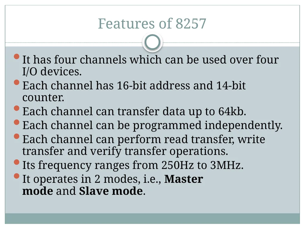
Features of 8257 It has four channels which can be used over four I/O devices.
Each channel has 16-bit address and 14-bit counter.
Each channel can transfer data up to 64kb.
Each channel can be programmed independently.
Each channel can perform read transfer, write transfer and verify transfer operations.
Its frequency ranges from 250Hz to 3MHz.
It operates in 2 modes, i.e., Master mode and Slave mode.<br>
05
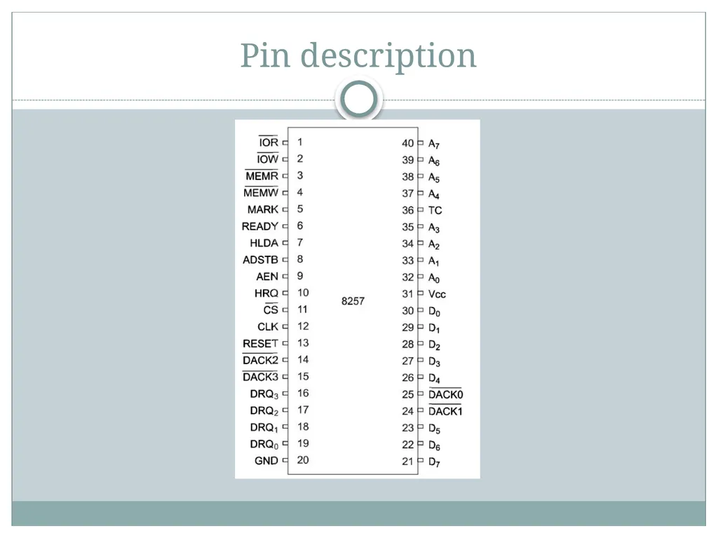
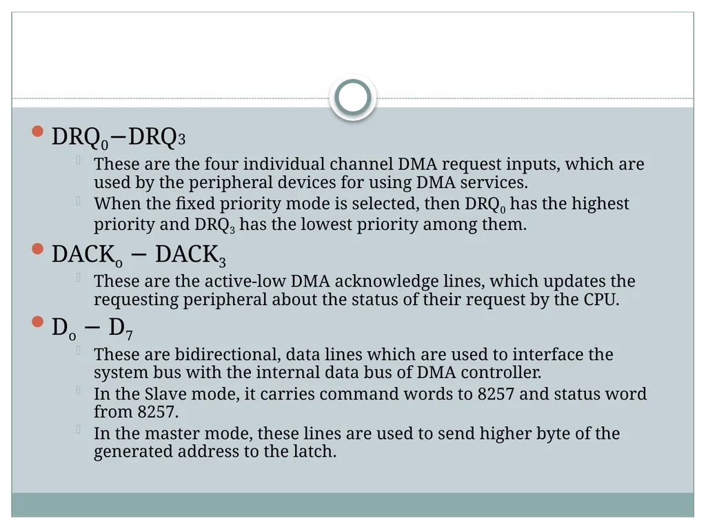
DRQ0−DRQ3
These are the four individual channel DMA request inputs, which are used by the peripheral devices for using DMA services.
When the fixed priority mode is selected, then DRQ0 has the highest priority and DRQ3 has the lowest priority among them.
DACKo − DACK3
These are the active-low DMA acknowledge lines, which updates the requesting peripheral about the status of their request by the CPU.
Do − D7
These are bidirectional, data lines which are used to interface the system bus with the internal data bus of DMA controller.
In the Slave mode, it carries command words to 8257 and status word from 8257.
In the master mode, these lines are used to send higher byte of the generated address to the latch.<br>
06
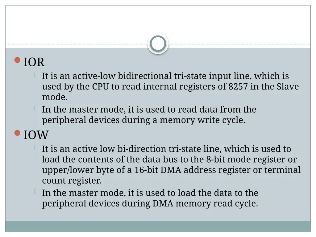
IOR
It is an active-low bidirectional tri-state input line, which is used by the CPU to read internal registers of 8257 in the Slave mode.
In the master mode, it is used to read data from the peripheral devices during a memory write cycle.
IOW
It is an active low bi-direction tri-state line, which is used to load the contents of the data bus to the 8-bit mode register or upper/lower byte of a 16-bit DMA address register or terminal count register.
In the master mode, it is used to load the data to the peripheral devices during DMA memory read cycle.<br>
07
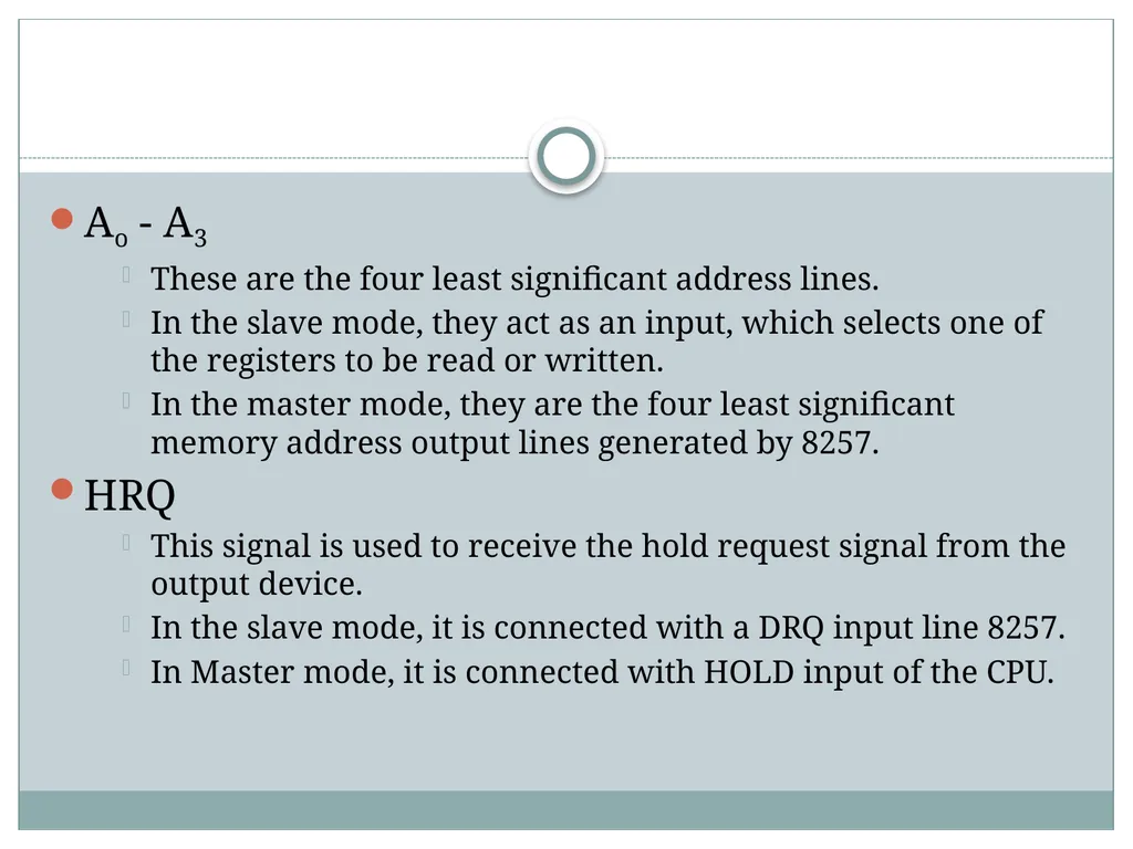
Ao - A3
These are the four least significant address lines.
In the slave mode, they act as an input, which selects one of the registers to be read or written.
In the master mode, they are the four least significant memory address output lines generated by 8257.
HRQ
This signal is used to receive the hold request signal from the output device.
In the slave mode, it is connected with a DRQ input line 8257.
In Master mode, it is connected with HOLD input of the CPU.<br>
08
HLDA
It is the hold acknowledgement signal which indicates the DMA controller that the bus has been granted to the requesting peripheral by the CPU when it is set to 1.
MEMR
It is the low memory read signal, which is used to read the data from the addressed memory locations during DMA read cycles.
MEMW
It is the active-low three state signal which is used to write the data to the addressed memory location during DMA write operation.<br>
09
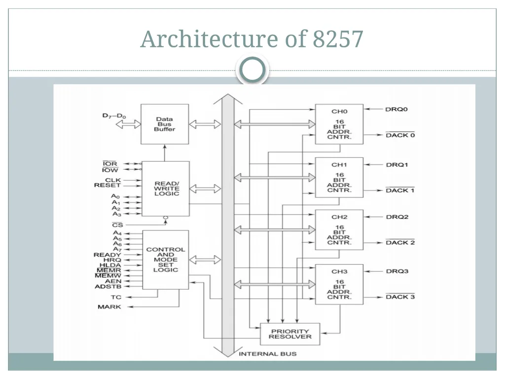
Architecture of 8257<br>
10
It consist of four channels.
i.e four peripheral devices can independently request for DMA data transfer through these channel at a time.
The DMA controller has 8-bit internal data buffer, a read/write unit, a control unit, a priority resolving unit along with a set of regsiters.<br>
11
Register organisation Each of the four channels has a pair of two 16-bit registers:
DMA address register
Terminal count register.
Two common register for all the channels:
mode set register
status register.
Total 10 registers.
CPU selects one of the 10 register using address line A0 to A3<br>
12
DMA address register Each channel has one DMA address register.
Function: to store the address of the starting memory location, which will be accessed by the DMA channel.
The address in the address register is automatically incremented after every read/write/verify transfer.<br>
13
Terminal count register The count register is used to count the number of byte or word transferred by DMA.
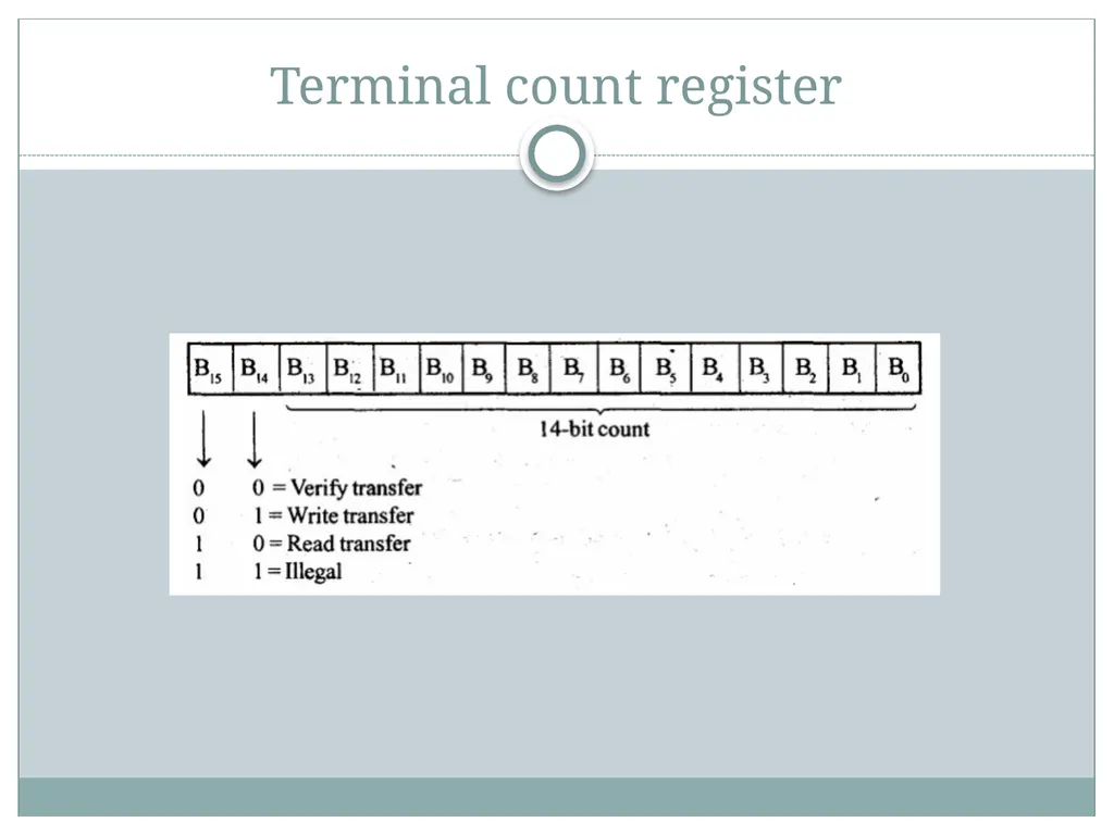
14-bits B0-B13 is used to count value and a 2-bits is used for indicate the type of DMA transfer (Read/Write/Verify transfer).
In read transfer the data is transferred from memory to I/O device.
In write transfer the data is transferred from I/O device to memory.
Verification operations generate the DMA addresses without generating the DMA memory and I/O control signals.<br>
14
Terminal count register<br>
15
Mode set register It is used for programming the 8257 as per the requirements of the system.
Function: to enable the DMA channels individually and also to set the various modes of operations.
A DMA channel should not be enabled till the DMA address register and the terminal count register contain valid information<br>
16
Mode set register Use of mode set register is,
Enable/disable a channel.
Fixed/rotating priority
Stop DMA on terminal count.
Extended/normal write time.
Auto reloading of channel-2.<br>
18
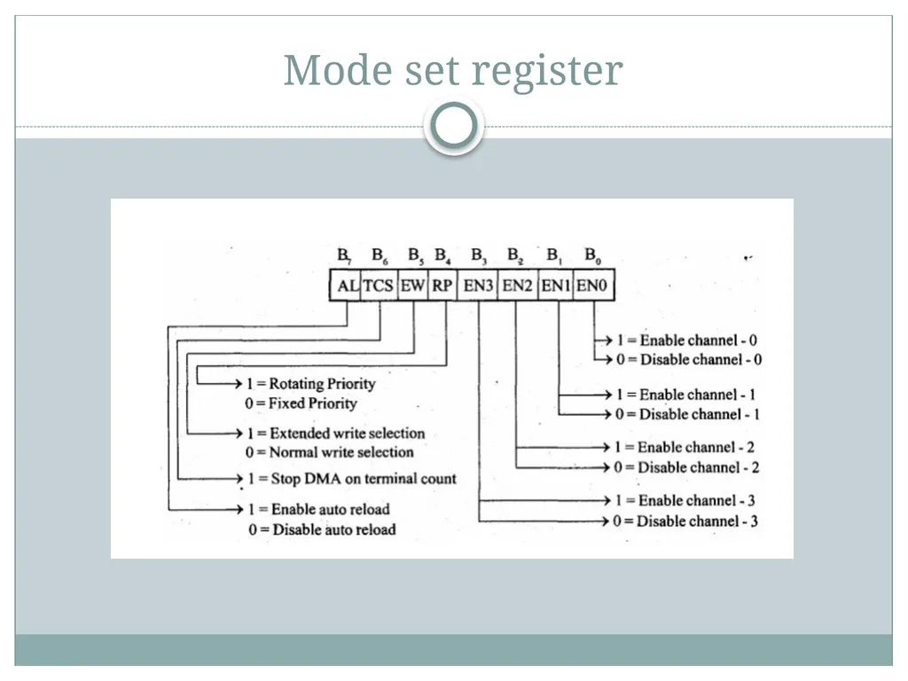
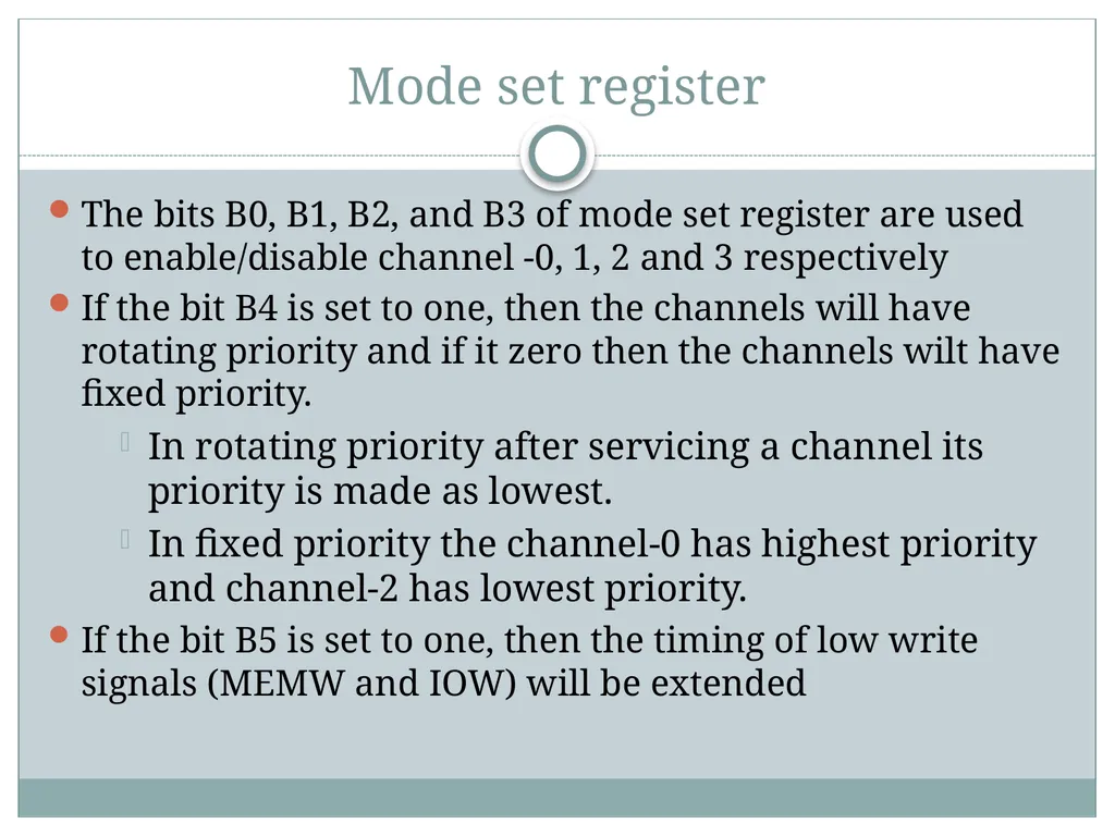
Mode set register The bits B0, B1, B2, and B3 of mode set register are used to enable/disable channel -0, 1, 2 and 3 respectively
If the bit B4 is set to one, then the channels will have rotating priority and if it zero then the channels wilt have fixed priority.
In rotating priority after servicing a channel its priority is made as lowest.
In fixed priority the channel-0 has highest priority and channel-2 has lowest priority.
If the bit B5 is set to one, then the timing of low write signals (MEMW and IOW) will be extended<br>
19
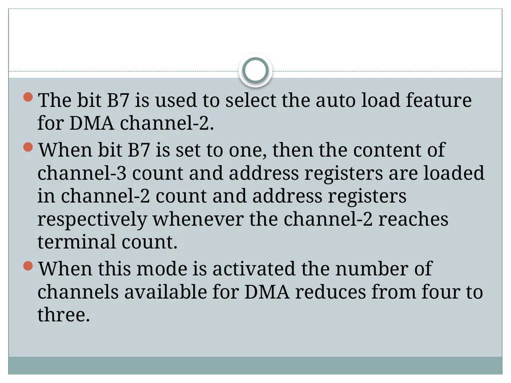
The bit B7 is used to select the auto load feature for DMA channel-2.
When bit B7 is set to one, then the content of channel-3 count and address registers are loaded in channel-2 count and address registers respectively whenever the channel-2 reaches terminal count.
When this mode is activated the number of channels available for DMA reduces from four to three.<br>
21
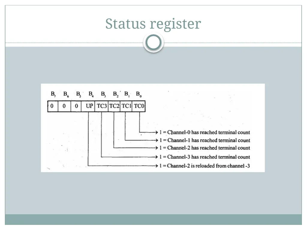
The bit B0, B1, B2, and B3 of status register indicates the terminal count status of channel-0, 1,2 and 3 respectively. A one in these bit positions indicates that the particular channel has reached terminal count.
These status bits are cleared after a read operation by microprocessor.
The bit B4 of status register is called update flag and a one in this bit position indicates that the channel-2 register has been reloaded from channel-3 registers in the auto load mode of operation.<br>
22
Read/write logic In the slave mode, the read/write logic accepts the I/O read or I/O write signals, decode the A0 t0 A3 lines and either writes the content of the data bus to the addressed internal register or read the contents of the selected register depending upon whether IOW or IOR signal is activated.
In the master mode, the read/write logic generates the IOR and IOW signals to control the data flow to or from the selected peripheral.<br>
23
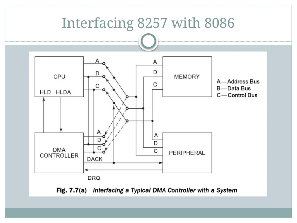
Working of DMA Microprocessor initializes the DMAC (DMA controller) by giving the starting address and the number of bytes to be transferred.
An I/O device requests the DMAC to perform DMA transfer through the DREQ line.
The DMAC in turn sends a request signal to the microprocessor through the HOLD line.
The microprocessor finishes the current machine cycle and releases the system bus (gets disconnected from it). It also acknowledges receiving the HOLD signal through the HLDA line.
The DMAC acquires control of the system bus. The DMAC sends the DACK signal to the I/O peripheral and the DMA transfer begins.
After every byte is transferred, the address register is incremented (or decremented) and the count register is decremented.
This continues till the count reaches zero (Terminal count). Now the DMA transfer is completed.
At the end of the transfer, the system bus is released by the DMAC by making HOLD = 0. Thus microprocessor takes control of the system bus and continues its operation.<br>
24
Priorities of the DMA request Two types:
Fixed priority scheme
Rotating priority schme<br>
25
Interfacing 8257 with 8086<br>