
ACM-WS-2021 04 Jan. 2022 (C)RG@CSA,IISc Processor
MY
Published · 64 slides · 0 views

1 / 1

Description
ACM-WS-2021 04 Jan. 2022 (C)RGCSA,IISc Processor Datapath Introduction to ILP Architecture R. Govindarajan CSA SERC, IISc, Bangalore govindiisc.ac.in Overview of this Module Introduction Processor Datapath Pipelining Branch Prediction
Related Topics
Share
Embed code
Download this presentation From Below
"ACM-WS-2021 04 Jan. 2022 (C)RG@CSA,IISc Processor" is the property of its rightful owner. Permission is granted to download and print the materials on this website for personal, non-commercial use only, and to display it on your personal computer provided you do not modify the materials and that you retain all copyright notices contained in the materials. By downloading content from our website, you accept the terms of this agreement.
Presentation Transcript
01
ACM-WS-2021
04 Jan. 2022 (C)RG@CSA,IISc Processor Datapath & Introduction to ILP Architecture R. Govindarajan
CSA & SERC,
IISc, Bangalore
govind@iisc.ac.in<br>
04 Jan. 2022 (C)RG@CSA,IISc Processor Datapath & Introduction to ILP Architecture R. Govindarajan
CSA & SERC,
IISc, Bangalore
govind@iisc.ac.in<br>
02
Overview of this Module Introduction
Processor Datapath
Pipelining
Branch Prediction
Out-of-Order Issue/Execution<br>
Processor Datapath
Pipelining
Branch Prediction
Out-of-Order Issue/Execution<br>
03
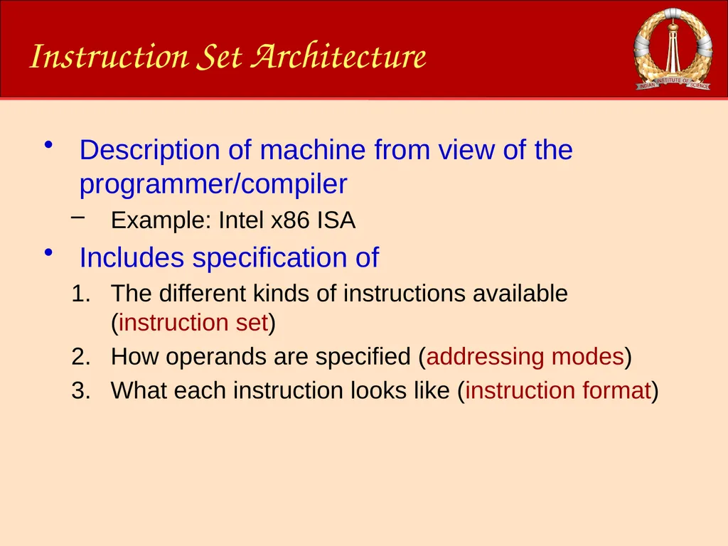
Instruction Set Architecture Description of machine from view of the programmer/compiler
Example: Intel x86 ISA
Includes specification of
The different kinds of instructions available (instruction set)
How operands are specified (addressing modes)
What each instruction looks like (instruction format)<br>
Example: Intel x86 ISA
Includes specification of
The different kinds of instructions available (instruction set)
How operands are specified (addressing modes)
What each instruction looks like (instruction format)<br>
04
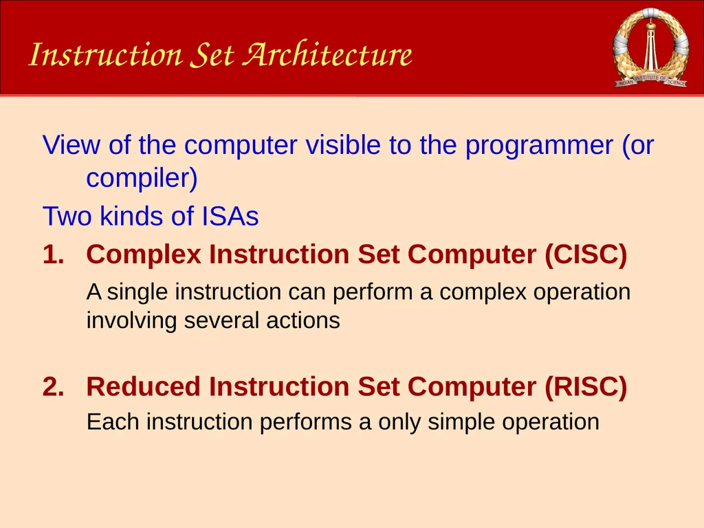
Instruction Set Architecture View of the computer visible to the programmer (or compiler)
Two kinds of ISAs
Complex Instruction Set Computer (CISC)
A single instruction can perform a complex operation involving several actions
Reduced Instruction Set Computer (RISC)
Each instruction performs a only simple operation<br>
Two kinds of ISAs
Complex Instruction Set Computer (CISC)
A single instruction can perform a complex operation involving several actions
Reduced Instruction Set Computer (RISC)
Each instruction performs a only simple operation<br>
05
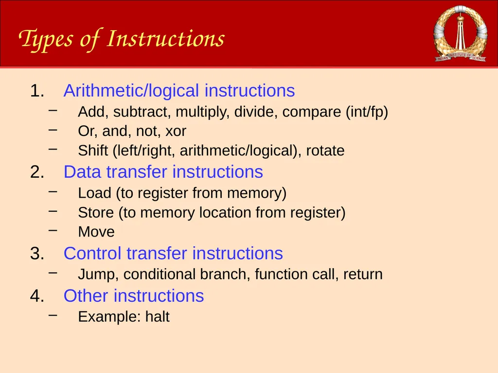
Types of Instructions Arithmetic/logical instructions
Add, subtract, multiply, divide, compare (int/fp)
Or, and, not, xor
Shift (left/right, arithmetic/logical), rotate
Data transfer instructions
Load (to register from memory)
Store (to memory location from register)
Move
Control transfer instructions
Jump, conditional branch, function call, return
Other instructions
Example: halt<br>
06
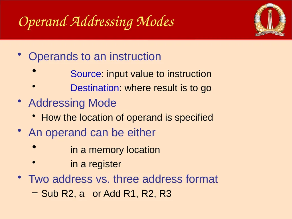
Operand Addressing Modes Operands to an instruction
Source: input value to instruction
Destination: where result is to go
Addressing Mode
How the location of operand is specified
An operand can be either
in a memory location
in a register
Two address vs. three address format
Sub R2, a or Add R1, R2, R3<br>
Source: input value to instruction
Destination: where result is to go
Addressing Mode
How the location of operand is specified
An operand can be either
in a memory location
in a register
Two address vs. three address format
Sub R2, a or Add R1, R2, R3<br>
07
Addressing Modes:
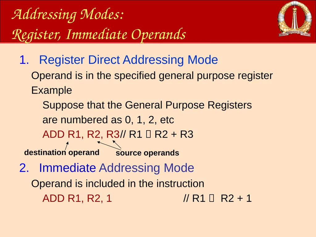
Register, Immediate Operands Register Direct Addressing Mode
Operand is in the specified general purpose register
Example
Suppose that the General Purpose Registers
are numbered as 0, 1, 2, etc
ADD R1, R2, R3 // R1 R2 + R3
Immediate Addressing Mode
Operand is included in the instruction
ADD R1, R2, 1 // R1 R2 + 1 source operands destination operand<br>
Operand is in the specified general purpose register
Example
Suppose that the General Purpose Registers
are numbered as 0, 1, 2, etc
ADD R1, R2, R3 // R1 R2 + R3
Immediate Addressing Mode
Operand is included in the instruction
ADD R1, R2, 1 // R1 R2 + 1 source operands destination operand<br>
08
Addressing Modes:
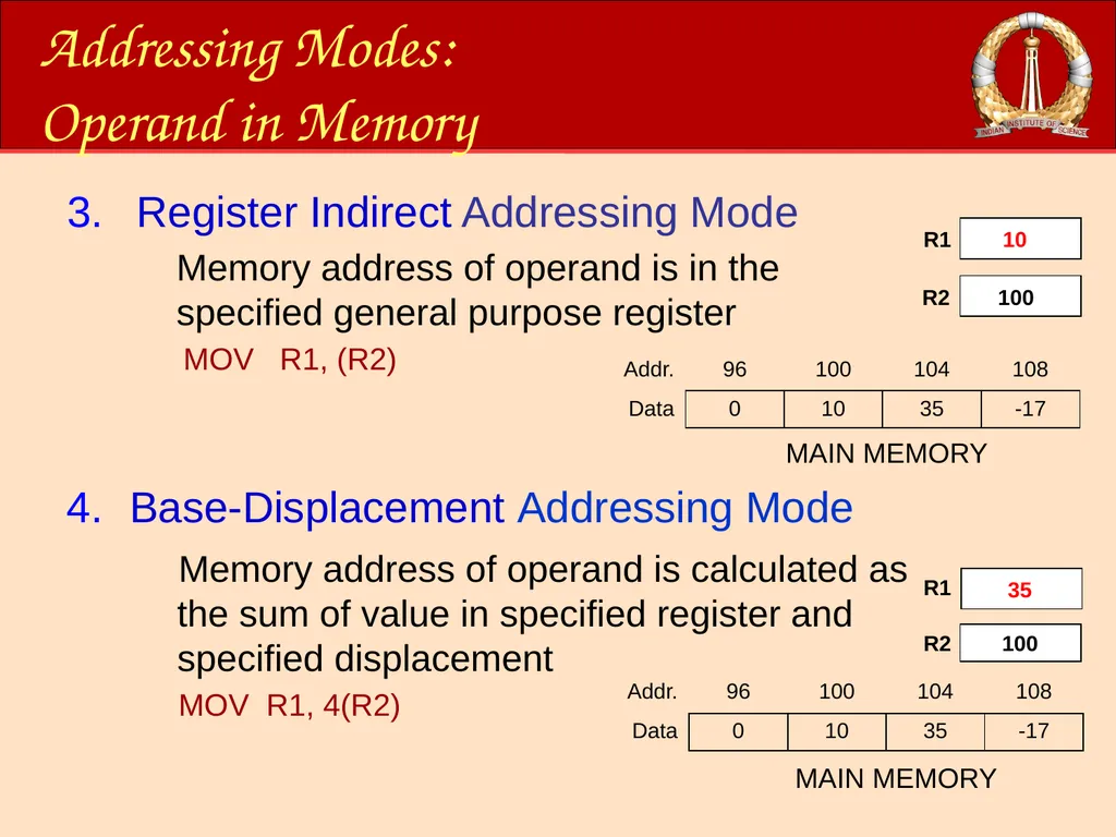
Operand in Memory Register Indirect Addressing Mode
Memory address of operand is in the specified general purpose register
MOV R1, (R2) Base-Displacement Addressing Mode R1 R1 R2 R2 32 100 32 100 MAIN MEMORY MAIN MEMORY 10 35 Memory address of operand is calculated as the sum of value in specified register and specified displacement
MOV R1, 4(R2)<br>
09
Addressing Modes:
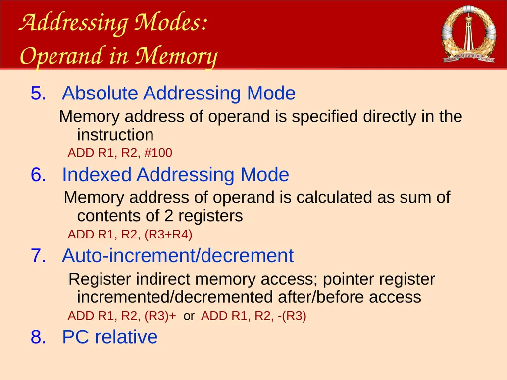
Operand in Memory Absolute Addressing Mode
Memory address of operand is specified directly in the instruction
ADD R1, R2, #100
Indexed Addressing Mode
Memory address of operand is calculated as sum of contents of 2 registers
ADD R1, R2, (R3+R4)
Auto-increment/decrement
Register indirect memory access; pointer register incremented/decremented after/before access
ADD R1, R2, (R3)+ or ADD R1, R2, -(R3)
PC relative<br>
10
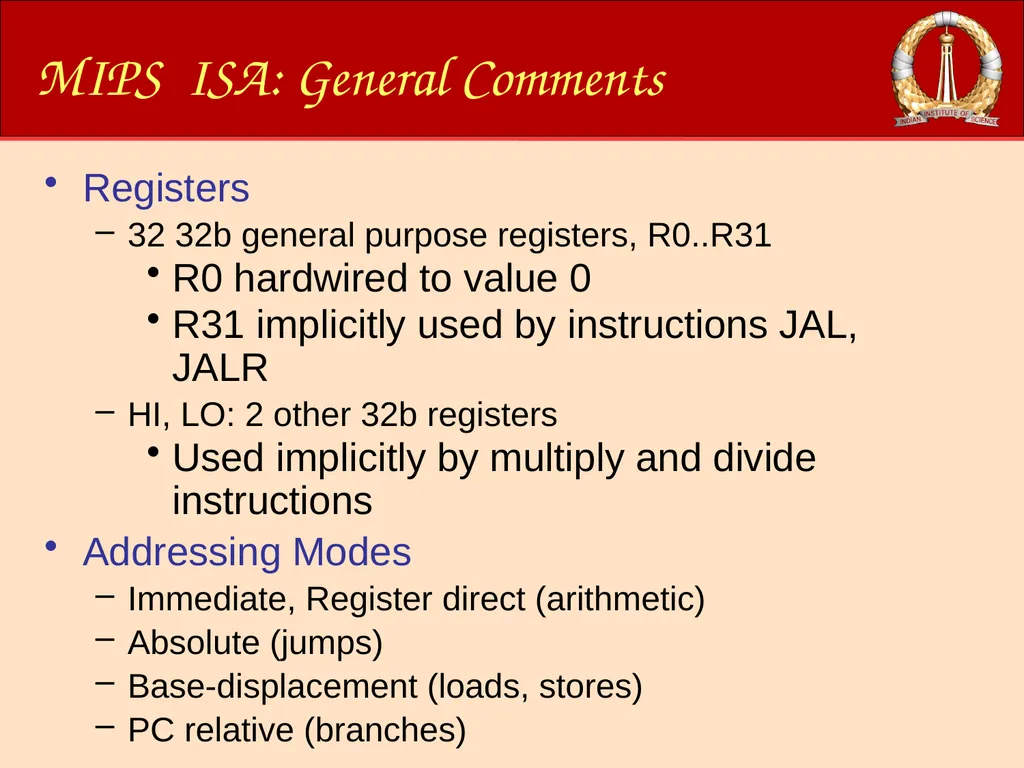
MIPS ISA: General Comments Registers
32 32b general purpose registers, R0..R31
R0 hardwired to value 0
R31 implicitly used by instructions JAL, JALR
HI, LO: 2 other 32b registers
Used implicitly by multiply and divide instructions
Addressing Modes
Immediate, Register direct (arithmetic)
Absolute (jumps)
Base-displacement (loads, stores)
PC relative (branches)<br>
11
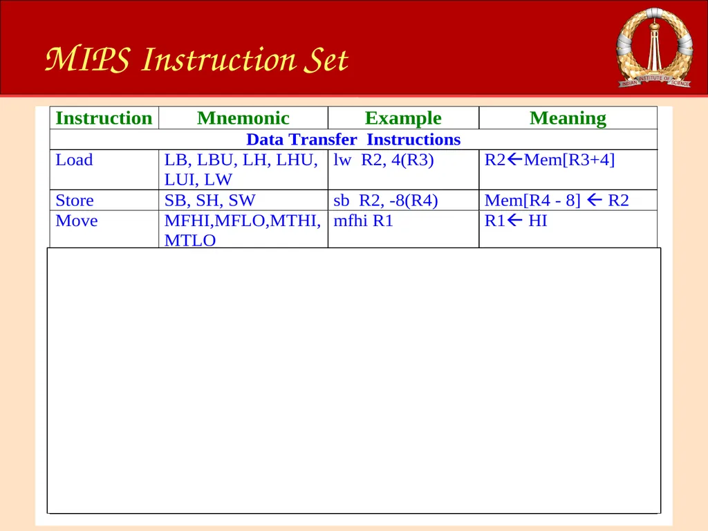
MIPS Instruction Set<br>
12
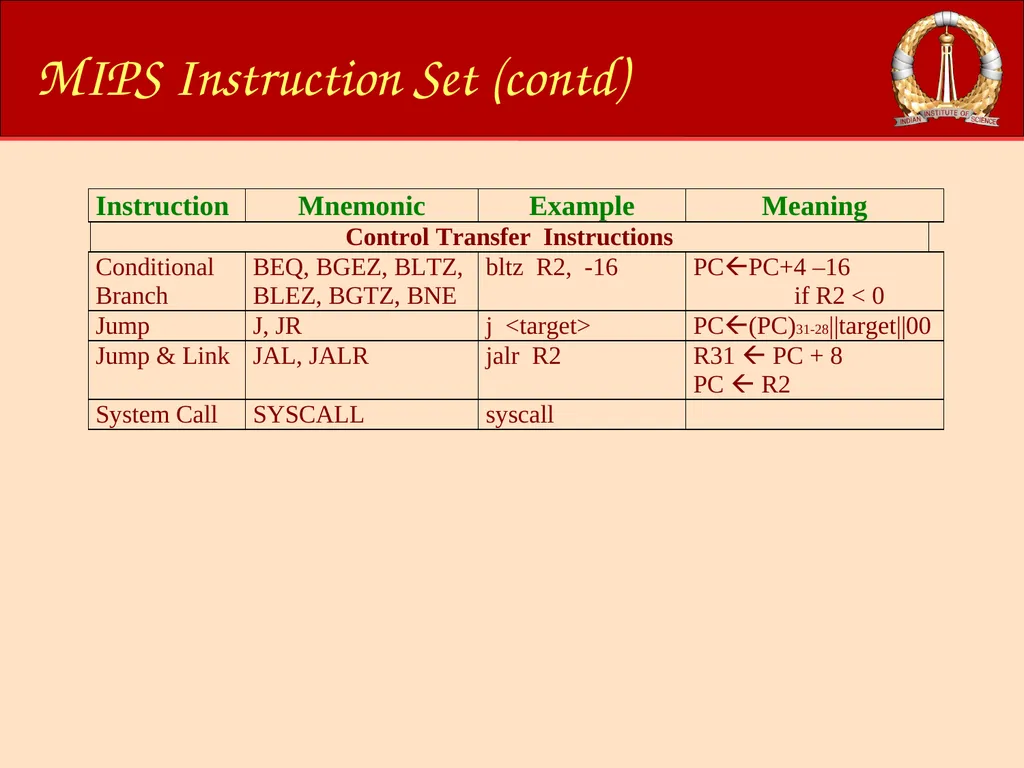
MIPS Instruction Set (contd)<br>
13
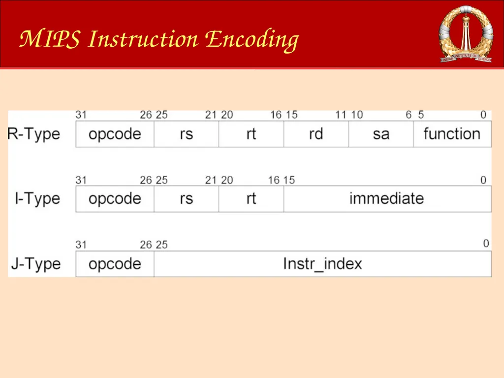
MIPS Instruction Encoding<br>
14
Overview of this Module Introduction
Processor Datapath
Pipelining
Branch Prediction
Out-of-Order Issue/Execution<br>
Processor Datapath
Pipelining
Branch Prediction
Out-of-Order Issue/Execution<br>
15
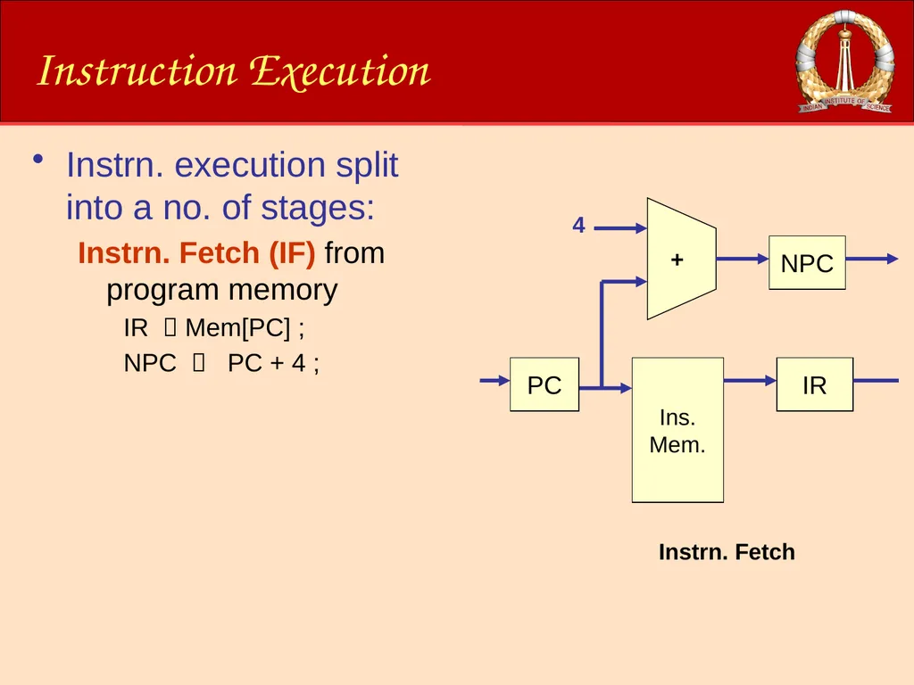
Instruction Execution Instrn. execution split into a no. of stages:
Instrn. Fetch (IF) from program memory
IR Mem[PC] ;
NPC PC + 4 ;<br>
Instrn. Fetch (IF) from program memory
IR Mem[PC] ;
NPC PC + 4 ;<br>
16
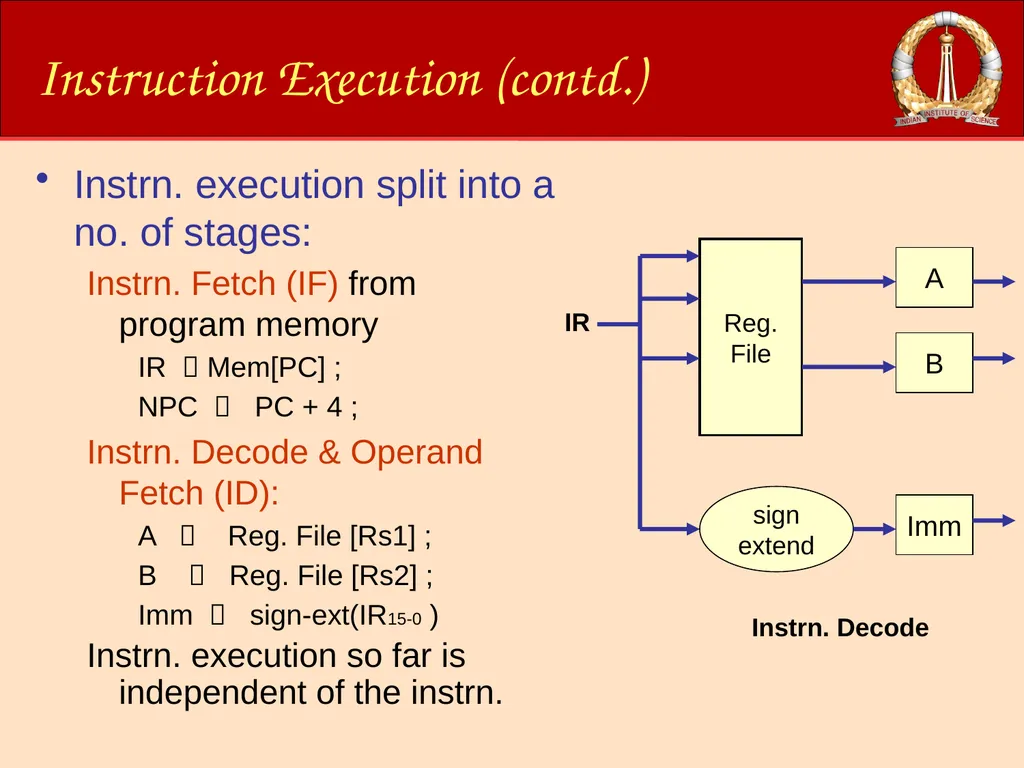
Instruction Execution (contd.) Instrn. execution split into a no. of stages:
Instrn. Fetch (IF) from program memory
IR Mem[PC] ;
NPC PC + 4 ;
Instrn. Decode & Operand Fetch (ID):
A Reg. File [Rs1] ;
B Reg. File [Rs2] ;
Imm sign-ext(IR15-0 )
Instrn. execution so far is independent of the instrn.<br>
Instrn. Fetch (IF) from program memory
IR Mem[PC] ;
NPC PC + 4 ;
Instrn. Decode & Operand Fetch (ID):
A Reg. File [Rs1] ;
B Reg. File [Rs2] ;
Imm sign-ext(IR15-0 )
Instrn. execution so far is independent of the instrn.<br>
17
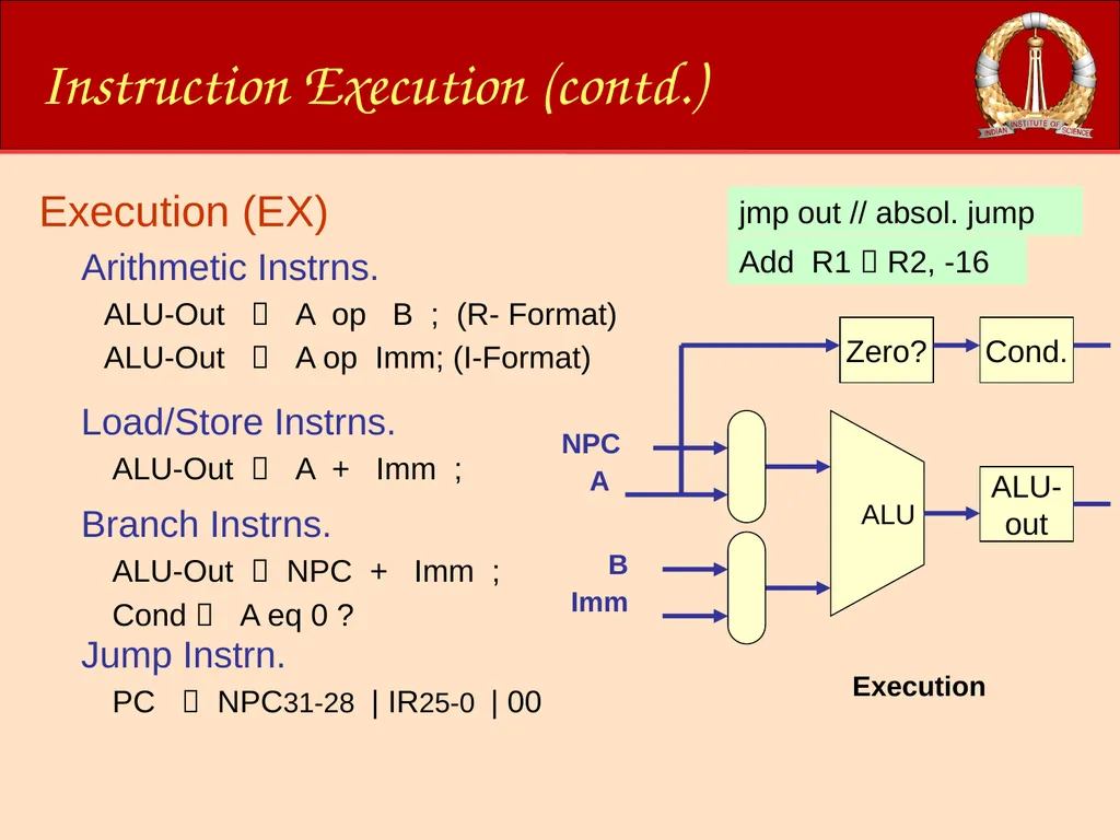
Instruction Execution (contd.) Execution (EX)
Arithmetic Instrns.
ALU-Out A op B ; (R- Format)
ALU-Out A op Imm; (I-Format) Add R1 R2, R3 Add R1 R2, -16 Ld R1 16(R2) bne R1, out // 16+NPC jmp out // absol. jump Load/Store Instrns.
ALU-Out A + Imm ; Branch Instrns.
ALU-Out NPC + Imm ;
Cond A eq 0 ? Jump Instrn.
PC NPC31-28 | IR25-0 | 00<br>
Arithmetic Instrns.
ALU-Out A op B ; (R- Format)
ALU-Out A op Imm; (I-Format) Add R1 R2, R3 Add R1 R2, -16 Ld R1 16(R2) bne R1, out // 16+NPC jmp out // absol. jump Load/Store Instrns.
ALU-Out A + Imm ; Branch Instrns.
ALU-Out NPC + Imm ;
Cond A eq 0 ? Jump Instrn.
PC NPC31-28 | IR25-0 | 00<br>
18
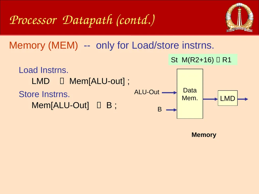
Processor Datapath (contd.) Memory Memory (MEM) -- only for Load/store instrns.
Load Instrns.
LMD Mem[ALU-out] ; Ld R1 M(R2+16) St M(R2+16) R1 Store Instrns.
Mem[ALU-Out] B ; ALU-Out B<br>
Load Instrns.
LMD Mem[ALU-out] ; Ld R1 M(R2+16) St M(R2+16) R1 Store Instrns.
Mem[ALU-Out] B ; ALU-Out B<br>
19
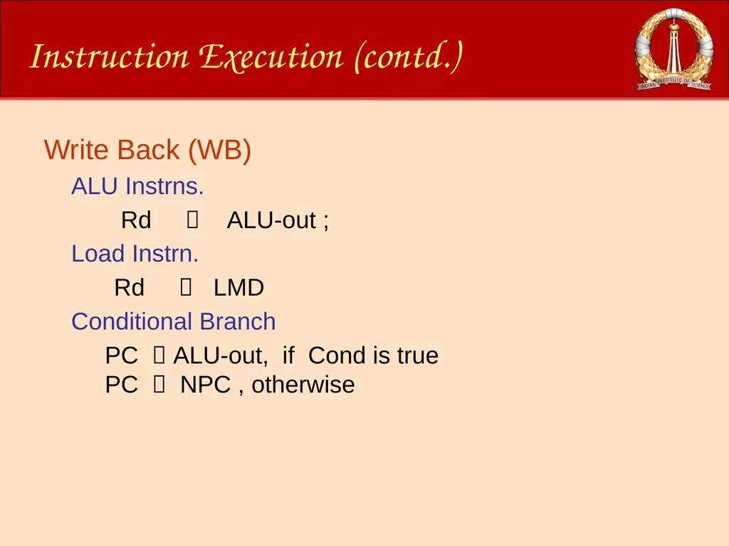
Instruction Execution (contd.) Write Back (WB)
ALU Instrns.
Rd ALU-out ;
Load Instrn.
Rd LMD
Conditional Branch
PC ALU-out, if Cond is true
PC NPC , otherwise<br>
ALU Instrns.
Rd ALU-out ;
Load Instrn.
Rd LMD
Conditional Branch
PC ALU-out, if Cond is true
PC NPC , otherwise<br>
20
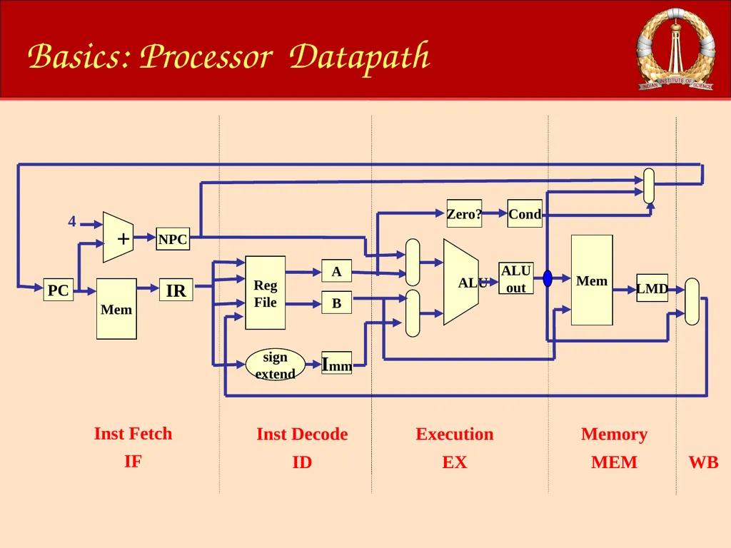
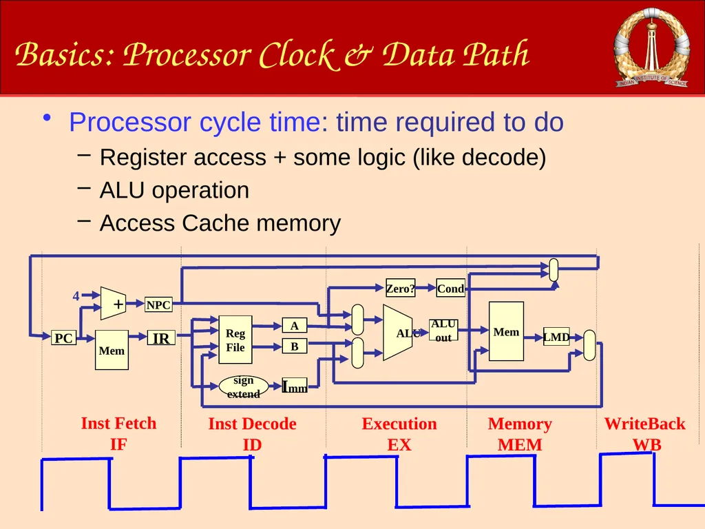
Basics: Processor Datapath Mem IR + PC NPC Reg
File sign
extend A Imm B Inst Fetch
IF Inst Decode
ID 4 ALU
out ALU Zero? Mem LMD Execution
EX Memory
MEM Cond WB<br>
File sign
extend A Imm B Inst Fetch
IF Inst Decode
ID 4 ALU
out ALU Zero? Mem LMD Execution
EX Memory
MEM Cond WB<br>
21
Basics: Processor Clock & Data Path Processor cycle time: time required to do
Register access + some logic (like decode)
ALU operation
Access Cache memory<br>
Register access + some logic (like decode)
ALU operation
Access Cache memory<br>
22
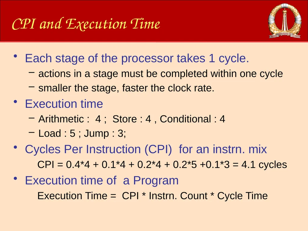
CPI and Execution Time Each stage of the processor takes 1 cycle.
actions in a stage must be completed within one cycle
smaller the stage, faster the clock rate.
Execution time
Arithmetic : 4 ; Store : 4 , Conditional : 4
Load : 5 ; Jump : 3;
Cycles Per Instruction (CPI) for an instrn. mix
CPI = 0.4*4 + 0.1*4 + 0.2*4 + 0.2*5 +0.1*3 = 4.1 cycles
Execution time of a Program
Execution Time = CPI * Instrn. Count * Cycle Time<br>
23
Overview of this Module Introduction
Processor Datapath
Pipelining
Branch Prediction
Out-of-Order Issue/Execution<br>
Processor Datapath
Pipelining
Branch Prediction
Out-of-Order Issue/Execution<br>
24
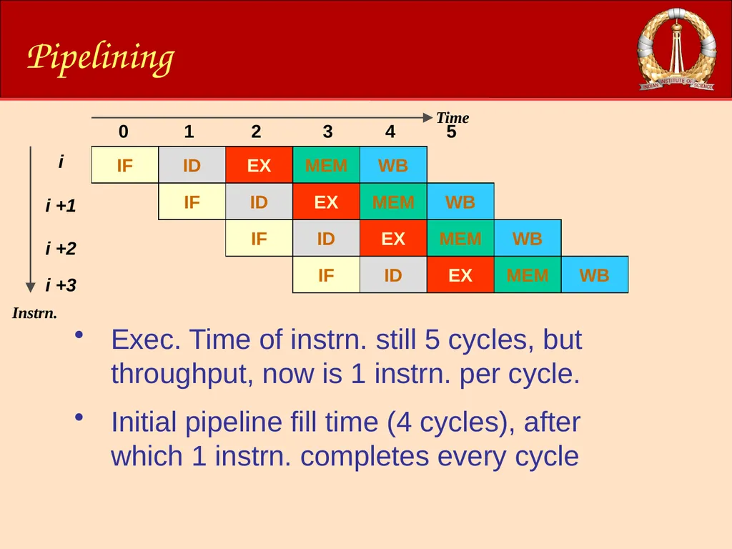
Pipelining Exec. Time of instrn. still 5 cycles, but throughput, now is 1 instrn. per cycle.
Initial pipeline fill time (4 cycles), after which 1 instrn. completes every cycle<br>
Initial pipeline fill time (4 cycles), after which 1 instrn. completes every cycle<br>
25
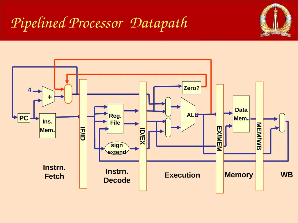
Pipelined Processor Datapath Ins.
Mem. + PC Reg.
File sign
extend Instrn. Fetch Instrn. Decode 4 ALU Zero? Data
Mem. Execution Memory WB IF/ID ID/EX EX/MEM MEM/WB<br>
Mem. + PC Reg.
File sign
extend Instrn. Fetch Instrn. Decode 4 ALU Zero? Data
Mem. Execution Memory WB IF/ID ID/EX EX/MEM MEM/WB<br>
26
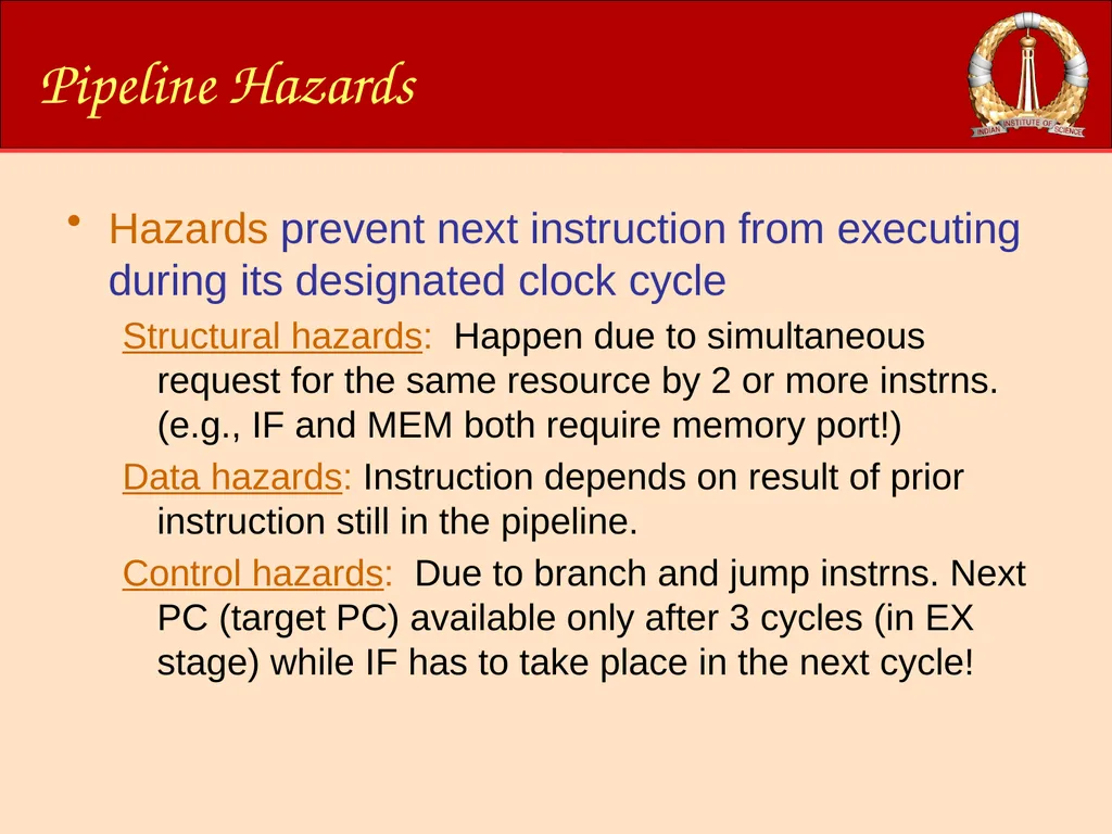
Pipeline Hazards Hazards prevent next instruction from executing during its designated clock cycle
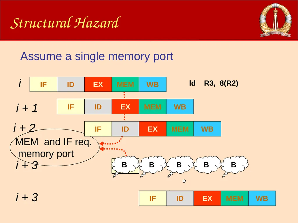
Structural hazards: Happen due to simultaneous request for the same resource by 2 or more instrns. (e.g., IF and MEM both require memory port!)
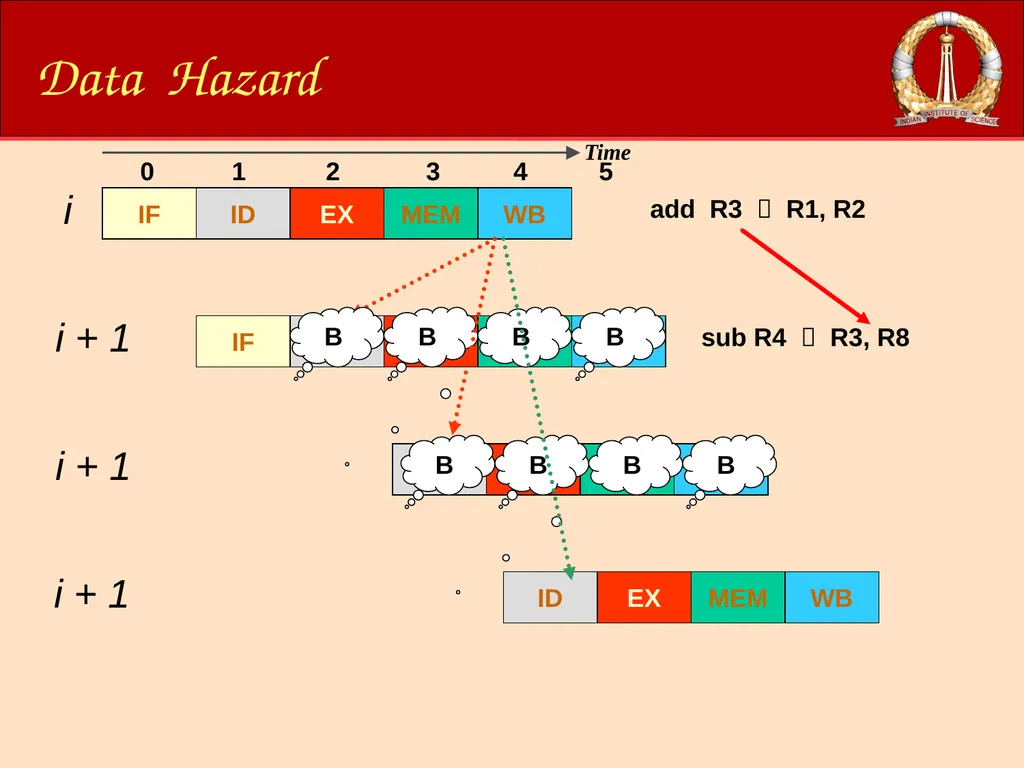
Data hazards: Instruction depends on result of prior instruction still in the pipeline.
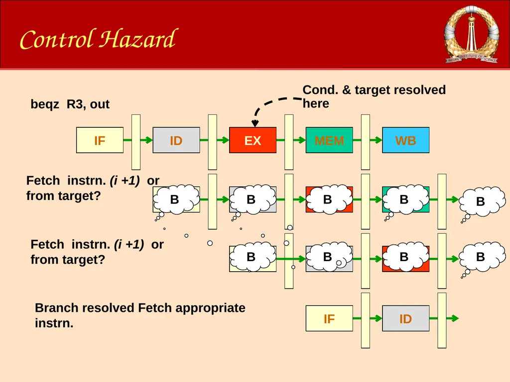
Control hazards: Due to branch and jump instrns. Next PC (target PC) available only after 3 cycles (in EX stage) while IF has to take place in the next cycle!<br>
27
Structural Hazard B Assume a single memory port<br>
28
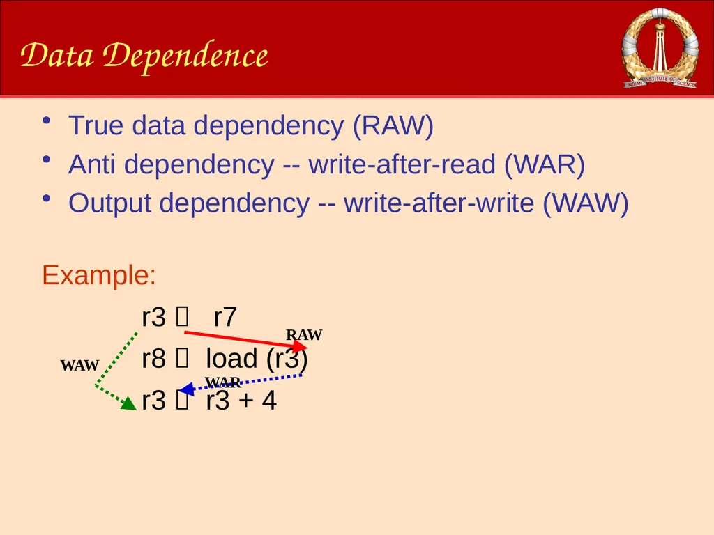
Data Dependence True data dependency (RAW)
Anti dependency -- write-after-read (WAR)
Output dependency -- write-after-write (WAW)
Example:
r3 r7
r8 load (r3)
r3 r3 + 4<br>
Anti dependency -- write-after-read (WAR)
Output dependency -- write-after-write (WAW)
Example:
r3 r7
r8 load (r3)
r3 r3 + 4<br>
29
Data Hazard Time 0 1 2 3 4 5<br>
30
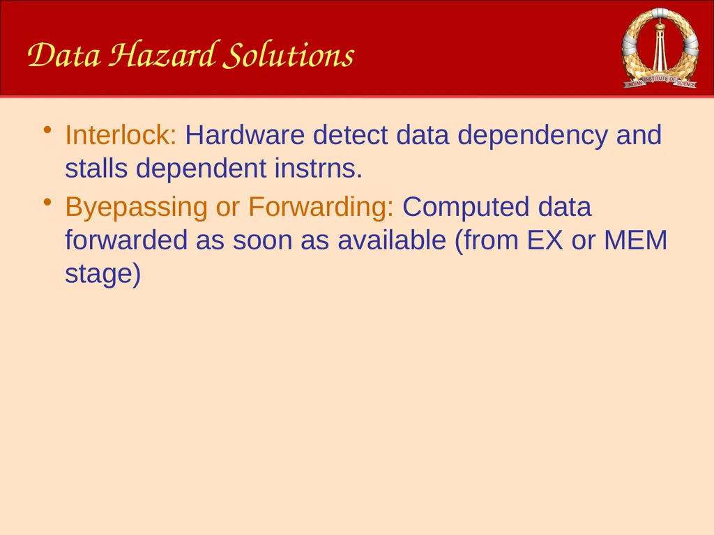
Data Hazard Solutions Interlock: Hardware detect data dependency and stalls dependent instrns.
Byepassing or Forwarding: Computed data forwarded as soon as available (from EX or MEM stage)<br>
Byepassing or Forwarding: Computed data forwarded as soon as available (from EX or MEM stage)<br>
31
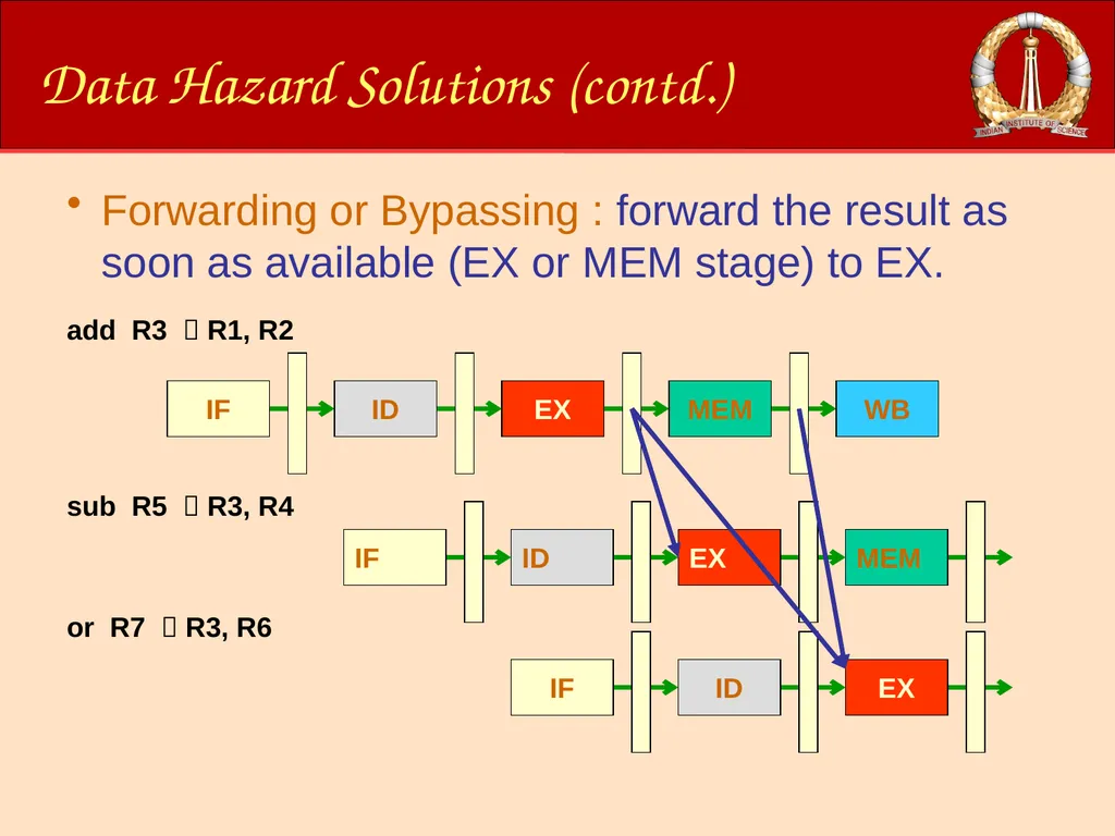
Data Hazard Solutions (contd.) Forwarding or Bypassing : forward the result as soon as available (EX or MEM stage) to EX. add R3 R1, R2 or R7 R3, R6 sub R5 R3, R4<br>
32
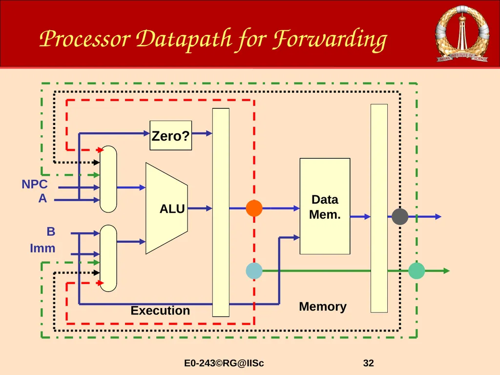
32 Processor Datapath for Forwarding Imm NPC ALU Zero? Data
Mem. Execution Memory B A E0-243©RG@IISc<br>
Mem. Execution Memory B A E0-243©RG@IISc<br>
33
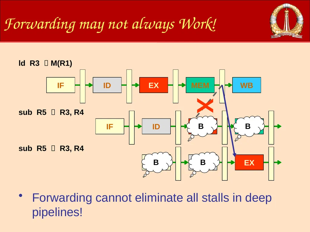
Forwarding may not always Work! ld R3 M(R1) sub R5 R3, R4 sub R5 R3, R4 Forwarding cannot eliminate all stalls in deep pipelines! B B B B X<br>
34
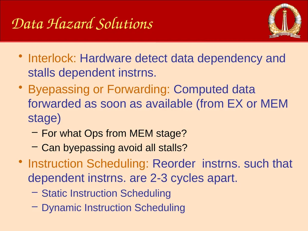
Data Hazard Solutions Interlock: Hardware detect data dependency and stalls dependent instrns.
Byepassing or Forwarding: Computed data forwarded as soon as available (from EX or MEM stage)
For what Ops from MEM stage?
Can byepassing avoid all stalls?
Instruction Scheduling: Reorder instrns. such that dependent instrns. are 2-3 cycles apart.
Static Instruction Scheduling
Dynamic Instruction Scheduling<br>
35
Control Hazard<br>
36
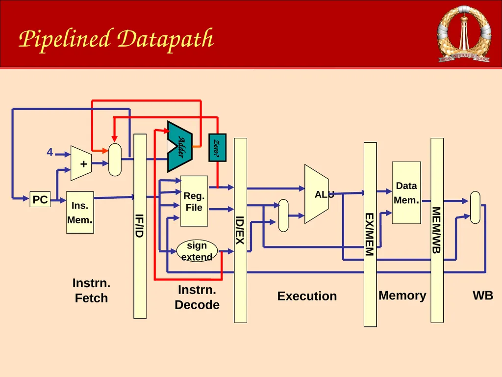
Pipelined Datapath Ins.
Mem. + PC Reg.
File sign
extend Instrn. Fetch Instrn. Decode 4 ALU Data
Mem. Execution Memory WB IF/ID ID/EX EX/MEM MEM/WB Zero?<br>
Mem. + PC Reg.
File sign
extend Instrn. Fetch Instrn. Decode 4 ALU Data
Mem. Execution Memory WB IF/ID ID/EX EX/MEM MEM/WB Zero?<br>
37
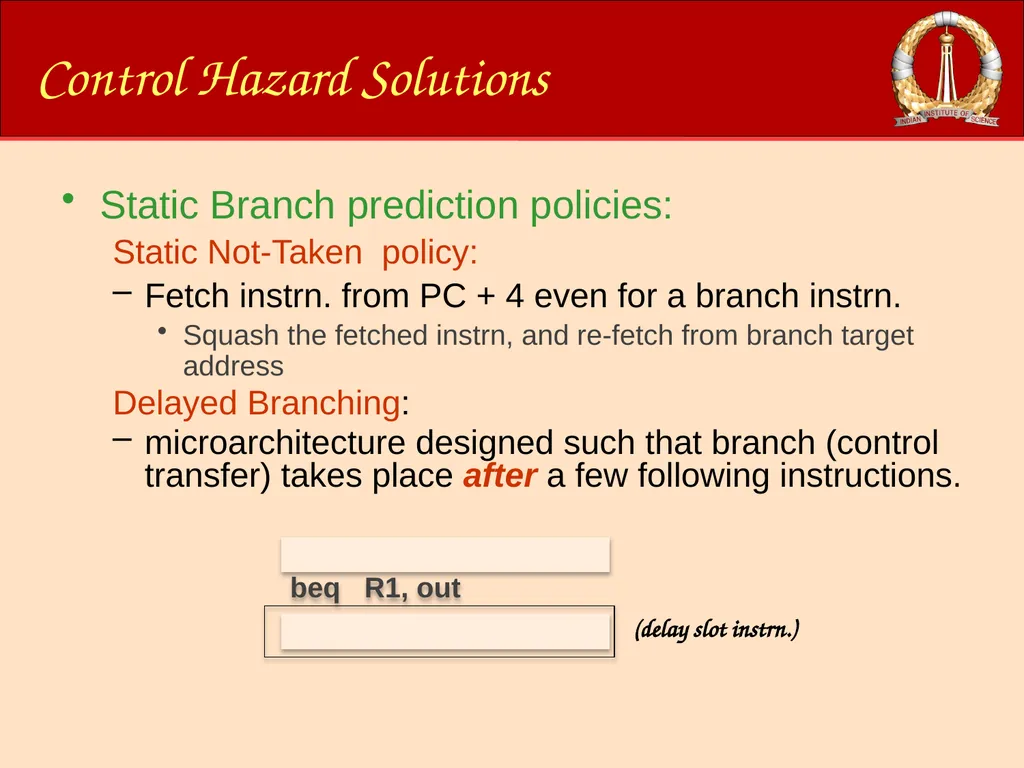
nop Control Hazard Solutions Static Branch prediction policies:
Static Not-Taken policy:
Fetch instrn. from PC + 4 even for a branch instrn.
Squash the fetched instrn, and re-fetch from branch target address
Delayed Branching:
microarchitecture designed such that branch (control transfer) takes place after a few following instructions. (delay slot instrn.) add R3 R2, R4 beq R1, out add R3 R2, R4<br>
38
Overview of this Module Introduction
Processor Datapath
Pipelining
Branch Prediction
Out-of-Order Issue/Execution<br>
Processor Datapath
Pipelining
Branch Prediction
Out-of-Order Issue/Execution<br>
39
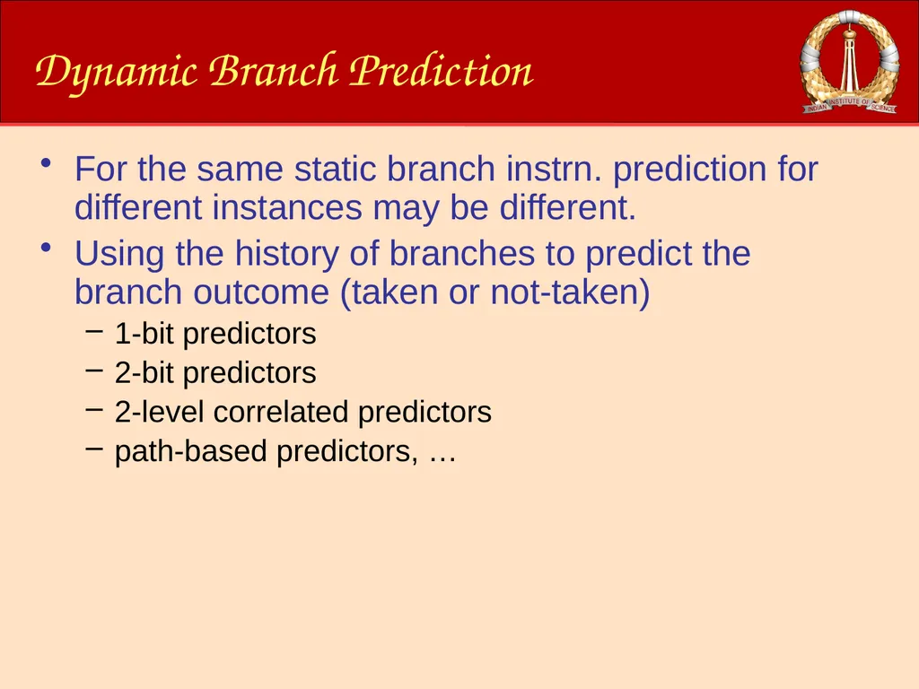
Dynamic Branch Prediction For the same static branch instrn. prediction for different instances may be different.
Using the history of branches to predict the branch outcome (taken or not-taken)
1-bit predictors
2-bit predictors
2-level correlated predictors
path-based predictors, …<br>
Using the history of branches to predict the branch outcome (taken or not-taken)
1-bit predictors
2-bit predictors
2-level correlated predictors
path-based predictors, …<br>
40
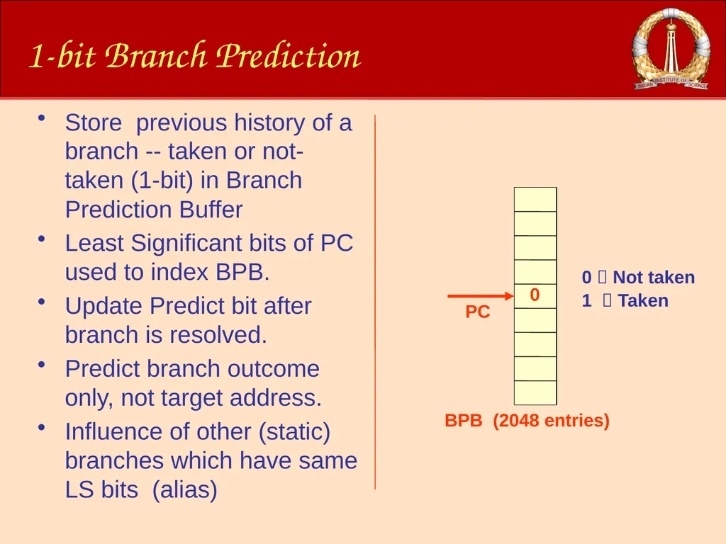
1-bit Branch Prediction Store previous history of a branch -- taken or not-taken (1-bit) in Branch Prediction Buffer
Least Significant bits of PC used to index BPB.
Update Predict bit after branch is resolved.
Predict branch outcome only, not target address.
Influence of other (static) branches which have same LS bits (alias) 0 Not taken
1 Taken<br>
Least Significant bits of PC used to index BPB.
Update Predict bit after branch is resolved.
Predict branch outcome only, not target address.
Influence of other (static) branches which have same LS bits (alias) 0 Not taken
1 Taken<br>
41
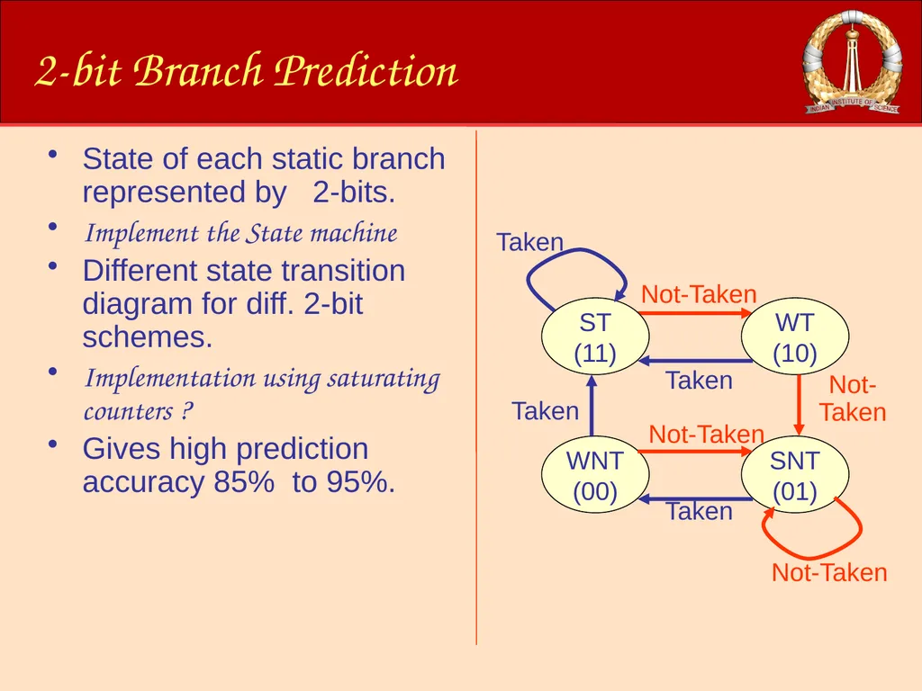
2-bit Branch Prediction State of each static branch represented by 2-bits.
Implement the State machine
Different state transition diagram for diff. 2-bit schemes.
Implementation using saturating counters ?
Gives high prediction accuracy 85% to 95%.<br>
Implement the State machine
Different state transition diagram for diff. 2-bit schemes.
Implementation using saturating counters ?
Gives high prediction accuracy 85% to 95%.<br>
42
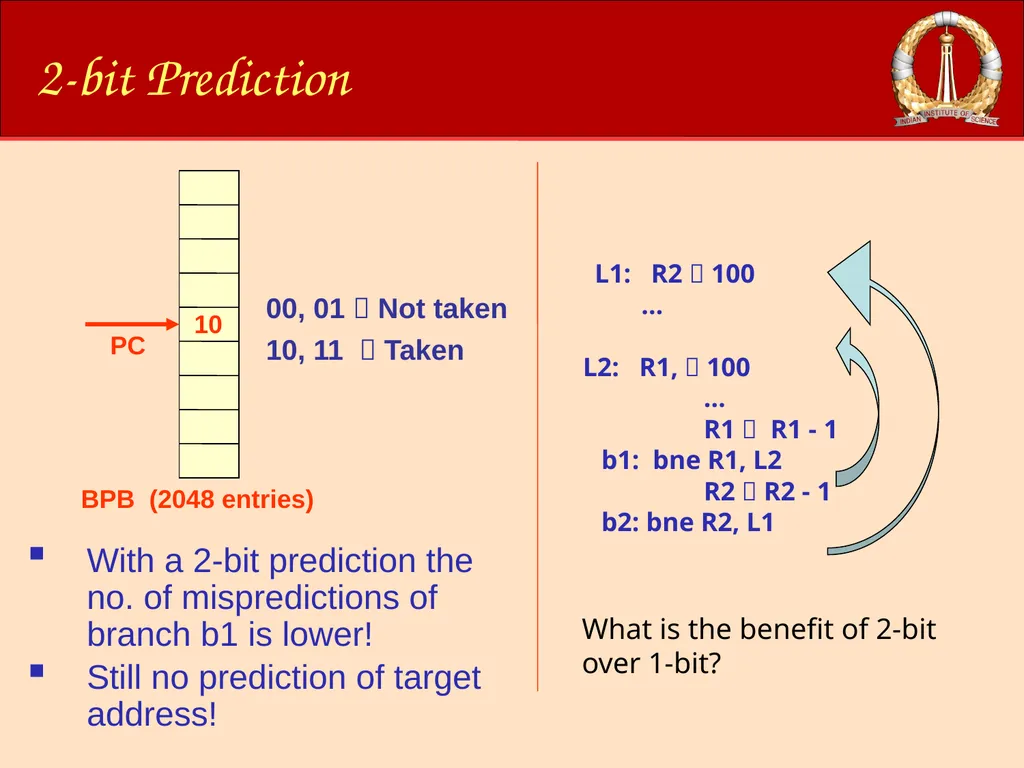
2-bit Prediction With a 2-bit prediction the no. of mispredictions of branch b1 is lower!
Still no prediction of target address! L1: R2 100
…
L2: R1, 100
…
R1 R1 - 1
b1: bne R1, L2
R2 R2 - 1
b2: bne R2, L1 00, 01 Not taken
10, 11 Taken What is the benefit of 2-bit over 1-bit?<br>
Still no prediction of target address! L1: R2 100
…
L2: R1, 100
…
R1 R1 - 1
b1: bne R1, L2
R2 R2 - 1
b2: bne R2, L1 00, 01 Not taken
10, 11 Taken What is the benefit of 2-bit over 1-bit?<br>
43
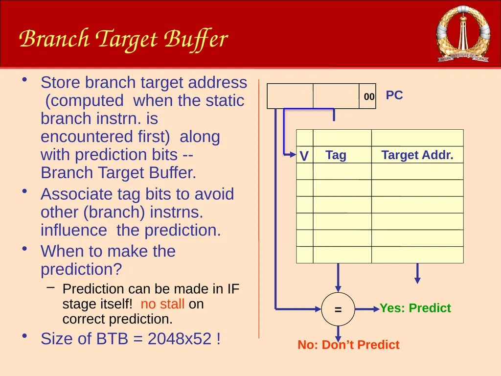
Branch Target Buffer Store branch target address (computed when the static branch instrn. is encountered first) along with prediction bits -- Branch Target Buffer.
Associate tag bits to avoid other (branch) instrns. influence the prediction.
When to make the prediction?
Prediction can be made in IF stage itself! no stall on correct prediction.
Size of BTB = 2048x52 !<br>
Associate tag bits to avoid other (branch) instrns. influence the prediction.
When to make the prediction?
Prediction can be made in IF stage itself! no stall on correct prediction.
Size of BTB = 2048x52 !<br>
44
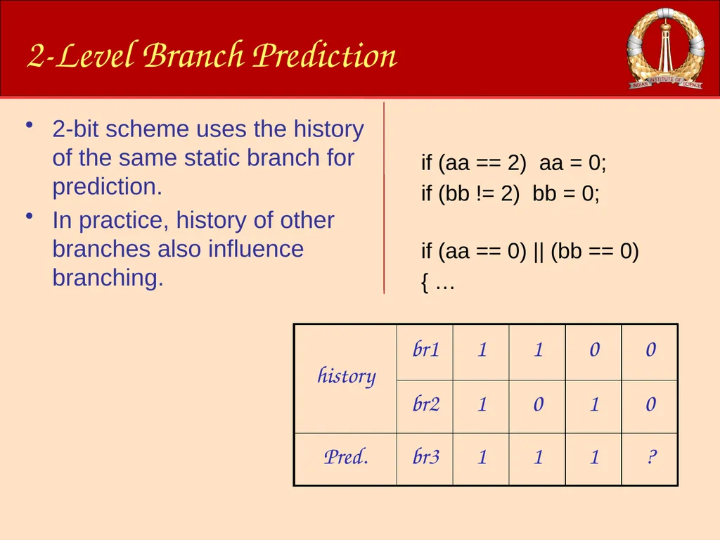
2-Level Branch Prediction 2-bit scheme uses the history of the same static branch for prediction.
In practice, history of other branches also influence branching. if (aa == 2) aa = 0;
if (bb != 2) bb = 0;
if (aa == 0) || (bb == 0)
{ …<br>
In practice, history of other branches also influence branching. if (aa == 2) aa = 0;
if (bb != 2) bb = 0;
if (aa == 0) || (bb == 0)
{ …<br>
45
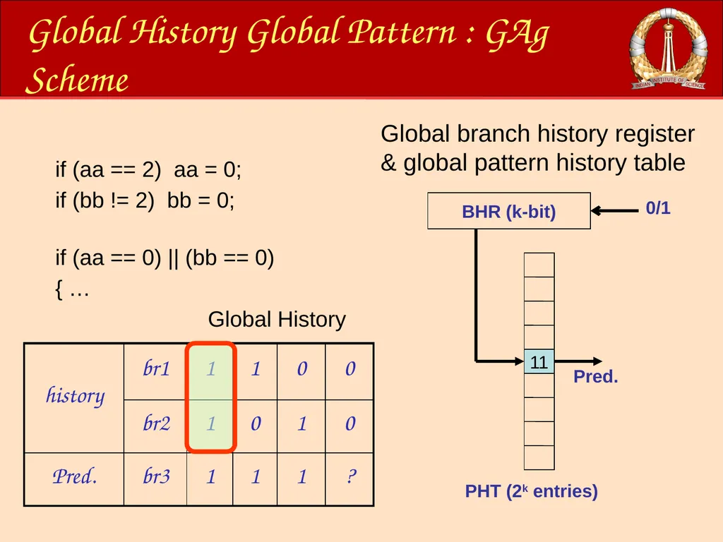
Global History Global Pattern : GAg Scheme Global branch history register & global pattern history table if (aa == 2) aa = 0;
if (bb != 2) bb = 0;
if (aa == 0) || (bb == 0)
{ … Global History<br>
if (bb != 2) bb = 0;
if (aa == 0) || (bb == 0)
{ … Global History<br>
46
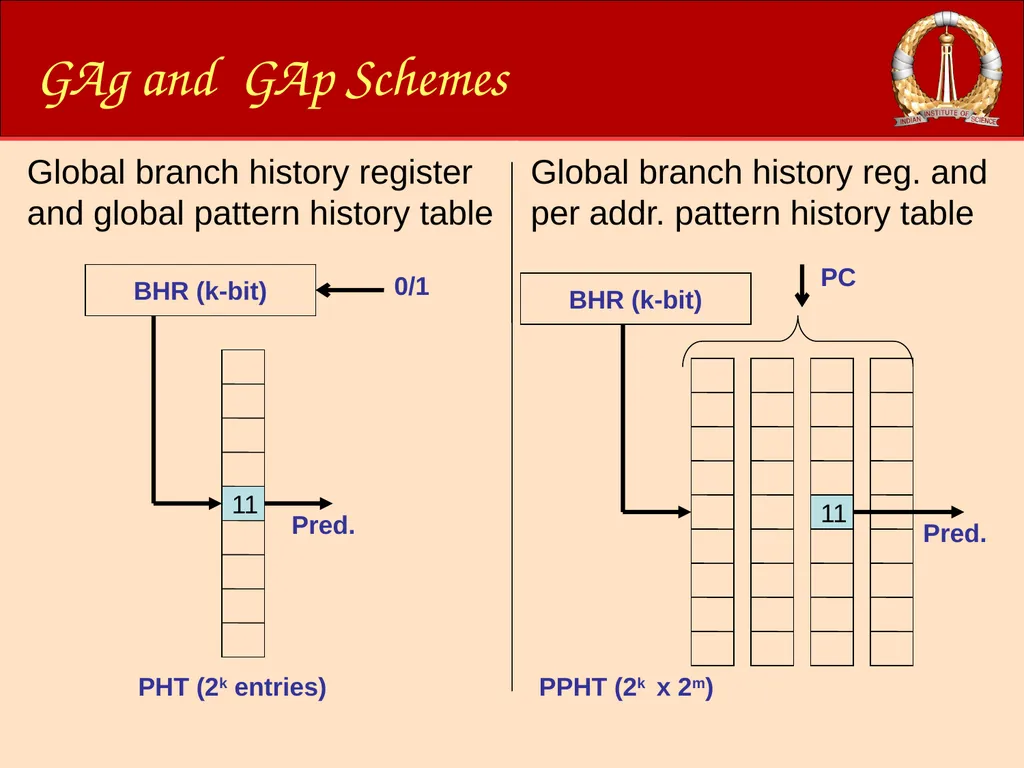
GAg and GAp Schemes BHR (k-bit) Pred. 11 PHT (2k entries) 0/1 Global branch history register and global pattern history table BHR (k-bit) Pred. 11 PPHT (2k x 2m) PC Global branch history reg. and per addr. pattern history table<br>
47
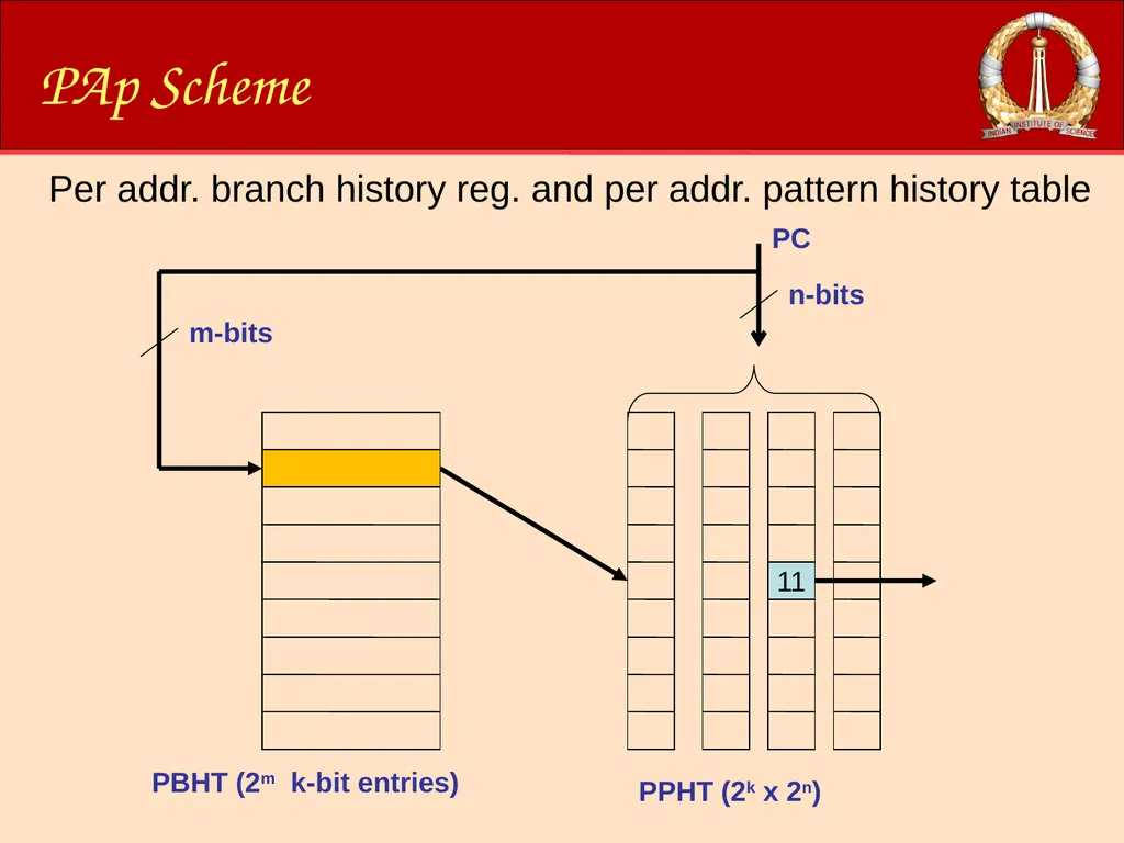
PAp Scheme 11 PPHT (2k x 2n) PC PBHT (2m k-bit entries) n-bits m-bits Per addr. branch history reg. and per addr. pattern history table<br>
48
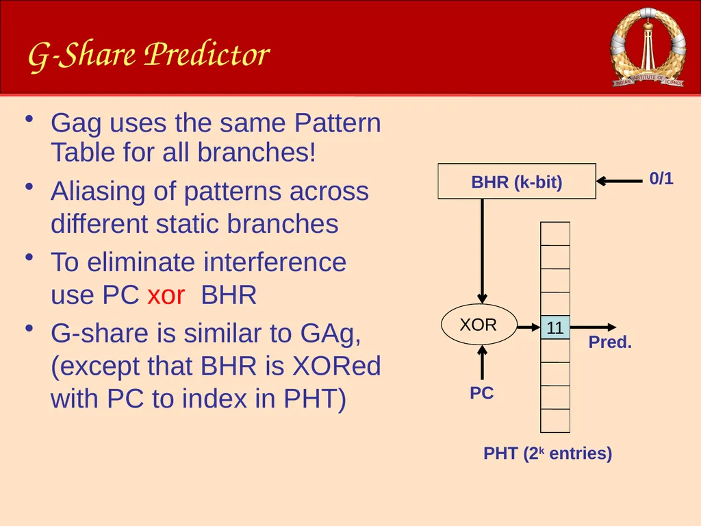
G-Share Predictor Gag uses the same Pattern Table for all branches!
Aliasing of patterns across different static branches
To eliminate interference use PC xor BHR
G-share is similar to GAg, (except that BHR is XORed with PC to index in PHT)<br>
Aliasing of patterns across different static branches
To eliminate interference use PC xor BHR
G-share is similar to GAg, (except that BHR is XORed with PC to index in PHT)<br>
49
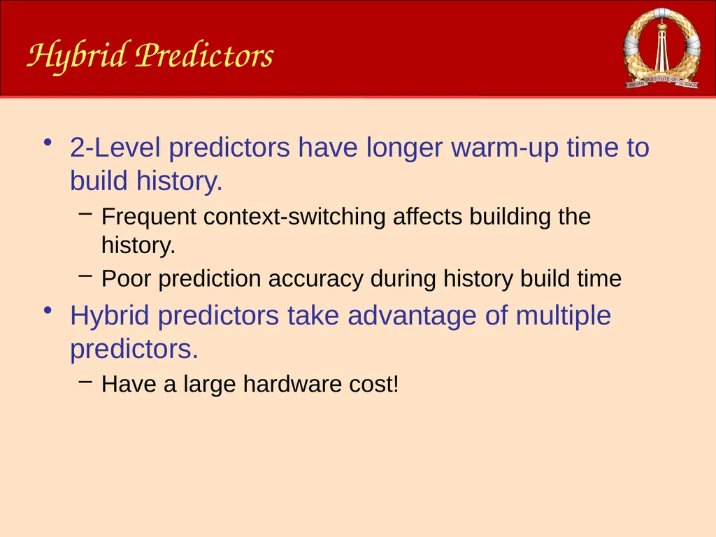
Hybrid Predictors 2-Level predictors have longer warm-up time to build history.
Frequent context-switching affects building the history.
Poor prediction accuracy during history build time
Hybrid predictors take advantage of multiple predictors.
Have a large hardware cost!<br>
Frequent context-switching affects building the history.
Poor prediction accuracy during history build time
Hybrid predictors take advantage of multiple predictors.
Have a large hardware cost!<br>
50
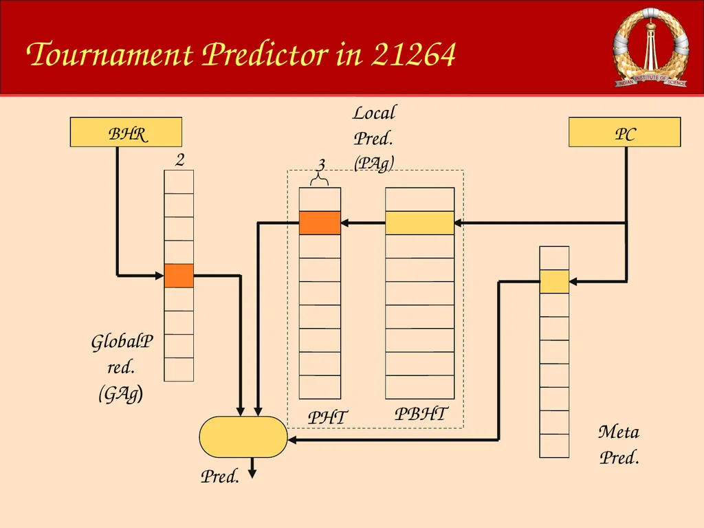
Tournament Predictor in 21264<br>
51
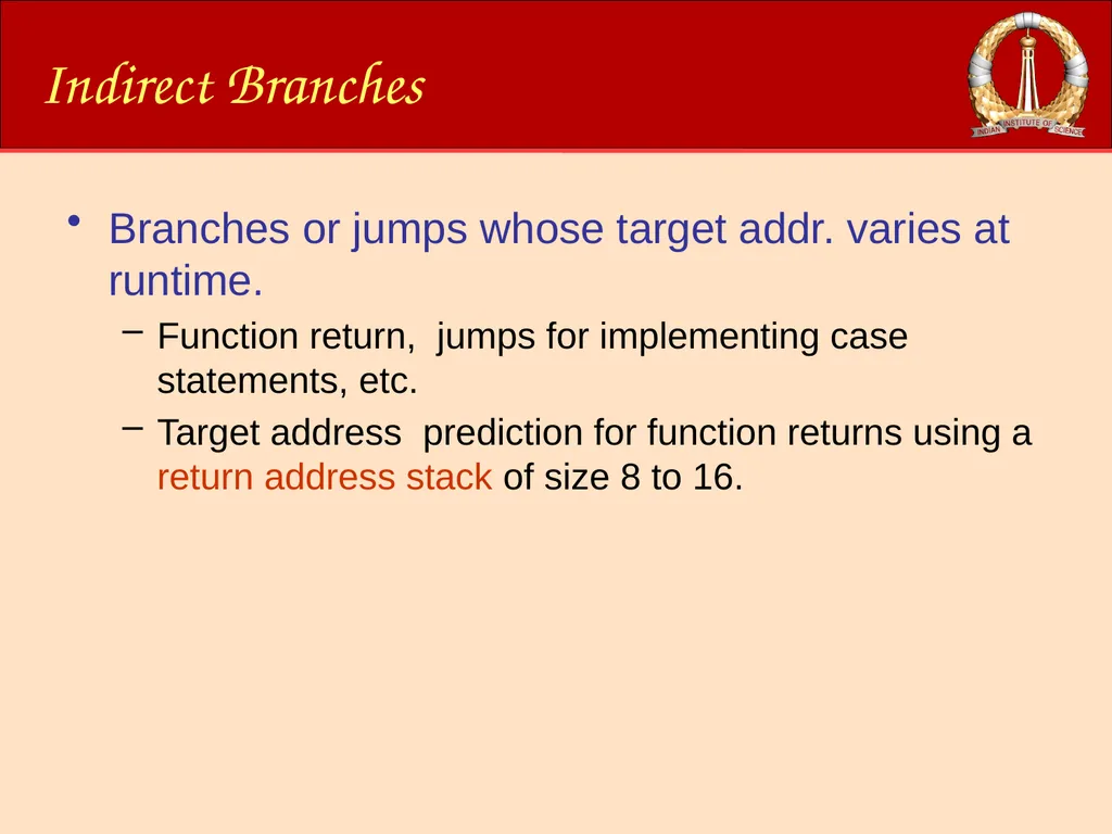
Indirect Branches Branches or jumps whose target addr. varies at runtime.
Function return, jumps for implementing case statements, etc.
Target address prediction for function returns using a return address stack of size 8 to 16.<br>
Function return, jumps for implementing case statements, etc.
Target address prediction for function returns using a return address stack of size 8 to 16.<br>
52
Overview of this Module Introduction
Instruction Set Architecture
Processor Datapath
Pipelining
Branch Prediction
Out-of-Order Issue/Execution<br>
Instruction Set Architecture
Processor Datapath
Pipelining
Branch Prediction
Out-of-Order Issue/Execution<br>
53
Towards ILP Architectures ILP Architecture
Ability to fetch, decode, issue and execute multiple instructions per cycle
Why? Improve the instruction execution throughput (Instructions Per Cycle (IPC)).<br>
Ability to fetch, decode, issue and execute multiple instructions per cycle
Why? Improve the instruction execution throughput (Instructions Per Cycle (IPC)).<br>
54
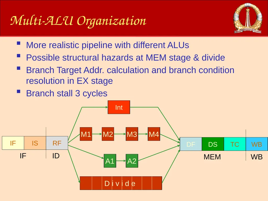
Multi-ALU Organization More realistic pipeline with different ALUs
Possible structural hazards at MEM stage & divide
Branch Target Addr. calculation and branch condition resolution in EX stage
Branch stall 3 cycles<br>
Possible structural hazards at MEM stage & divide
Branch Target Addr. calculation and branch condition resolution in EX stage
Branch stall 3 cycles<br>
55
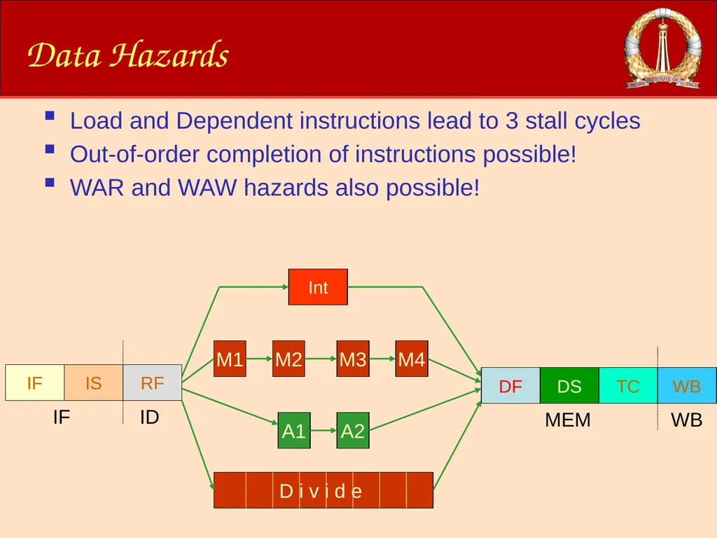
Data Hazards Load and Dependent instructions lead to 3 stall cycles
Out-of-order completion of instructions possible!
WAR and WAW hazards also possible!<br>
Out-of-order completion of instructions possible!
WAR and WAW hazards also possible!<br>
56
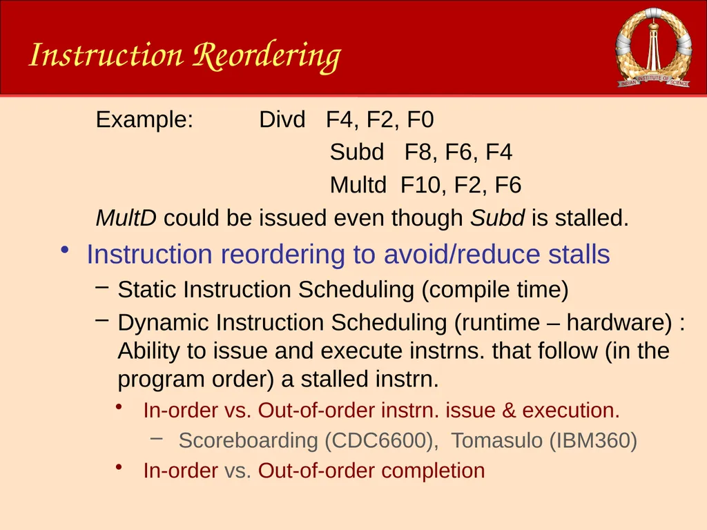
Instruction Reordering Example: Divd F4, F2, F0
Subd F8, F6, F4
Multd F10, F2, F6
MultD could be issued even though Subd is stalled.
Instruction reordering to avoid/reduce stalls
Static Instruction Scheduling (compile time)
Dynamic Instruction Scheduling (runtime – hardware) : Ability to issue and execute instrns. that follow (in the program order) a stalled instrn.
In-order vs. Out-of-order instrn. issue & execution.
Scoreboarding (CDC6600), Tomasulo (IBM360)
In-order vs. Out-of-order completion<br>
57
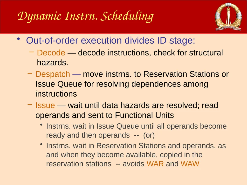
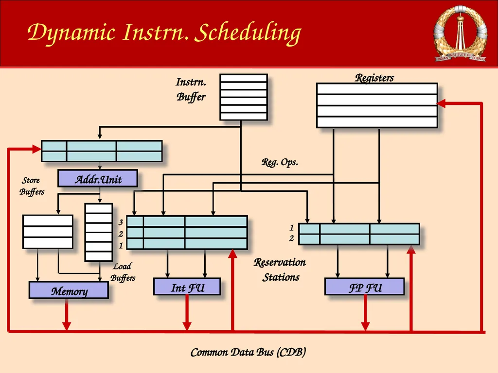
Out-of-order execution divides ID stage:
Decode — decode instructions, check for structural hazards.
Despatch — move instrns. to Reservation Stations or Issue Queue for resolving dependences among instructions
Issue — wait until data hazards are resolved; read operands and sent to Functional Units
Instrns. wait in Issue Queue until all operands become ready and then operands -- (or)
Instrns. wait in Reservation Stations and operands, as and when they become available, copied in the reservation stations -- avoids WAR and WAW Dynamic Instrn. Scheduling<br>
58
Dynamic Instrn. Scheduling Load
Buffers Addr.Unit<br>
Buffers Addr.Unit<br>
59
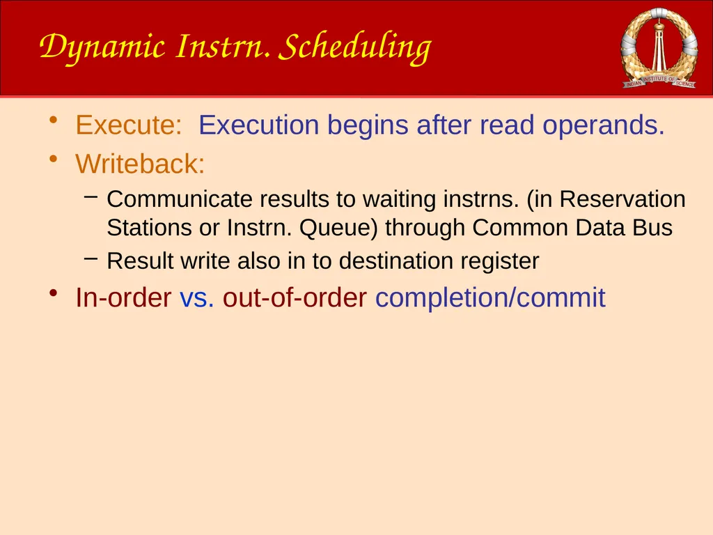
Execute: Execution begins after read operands.
Writeback:
Communicate results to waiting instrns. (in Reservation Stations or Instrn. Queue) through Common Data Bus
Result write also in to destination register
In-order vs. out-of-order completion/commit Dynamic Instrn. Scheduling<br>
Writeback:
Communicate results to waiting instrns. (in Reservation Stations or Instrn. Queue) through Common Data Bus
Result write also in to destination register
In-order vs. out-of-order completion/commit Dynamic Instrn. Scheduling<br>
60
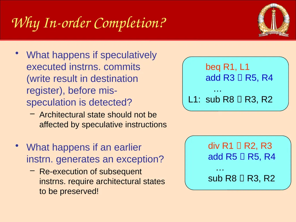
Why In-order Completion? What happens if speculatively executed instrns. commits (write result in destination register), before mis-speculation is detected?
Architectural state should not be affected by speculative instructions
What happens if an earlier instrn. generates an exception?
Re-execution of subsequent instrns. require architectural states to be preserved! beq R1, L1
add R3 R5, R4
…
L1: sub R8 R3, R2 div R1 R2, R3
add R5 R5, R4
…
sub R8 R3, R2<br>
61
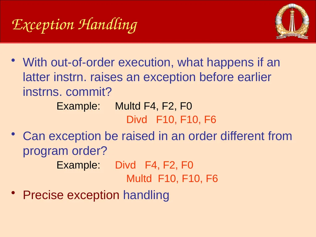
Exception Handling With out-of-order execution, what happens if an latter instrn. raises an exception before earlier instrns. commit?
Example: Multd F4, F2, F0
Divd F10, F10, F6
Can exception be raised in an order different from program order?
Example: Divd F4, F2, F0
Multd F10, F10, F6
Precise exception handling<br>
Example: Multd F4, F2, F0
Divd F10, F10, F6
Can exception be raised in an order different from program order?
Example: Divd F4, F2, F0
Multd F10, F10, F6
Precise exception handling<br>
62
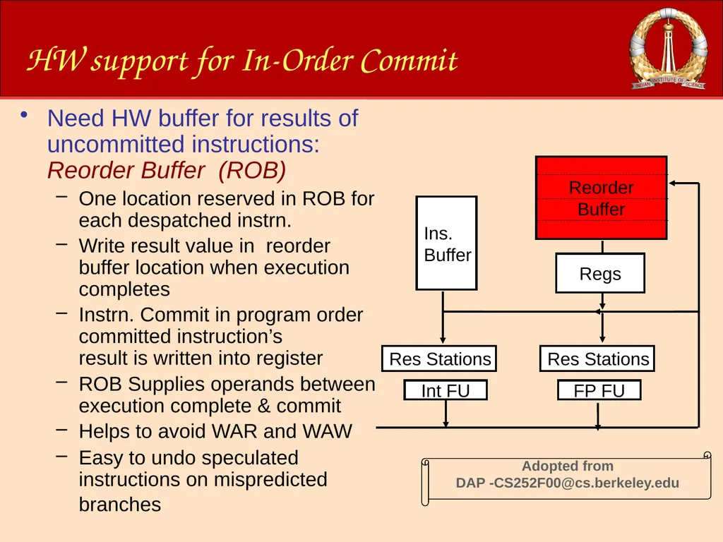
HW support for In-Order Commit Need HW buffer for results of uncommitted instructions: Reorder Buffer (ROB)
One location reserved in ROB for each despatched instrn.
Write result value in reorder buffer location when execution completes
Instrn. Commit in program order committed instruction’s result is written into register
ROB Supplies operands between execution complete & commit
Helps to avoid WAR and WAW
Easy to undo speculated instructions on mispredicted branches Reorder
Buffer Ins.
Buffer Int FU FP FU Res Stations Res Stations Regs<br>
63
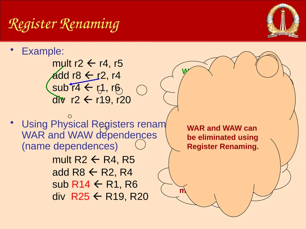
Register Renaming Example:
mult r2 r4, r5
add r8 r2, r4
sub r4 r1, r6
div r2 r19, r20
Using Physical Registers rename WAR and WAW dependences (name dependences)
mult R2 R4, R5
add R8 R2, R4
sub R14 R1, R6
div R25 R19, R20 WAR dependency. sub cannot proceed for execution until
add reads r4 WAW dependency. Div cannot proceed for execution until mult completes exec. WAR and WAW can be eliminated using Register Renaming.<br>
64
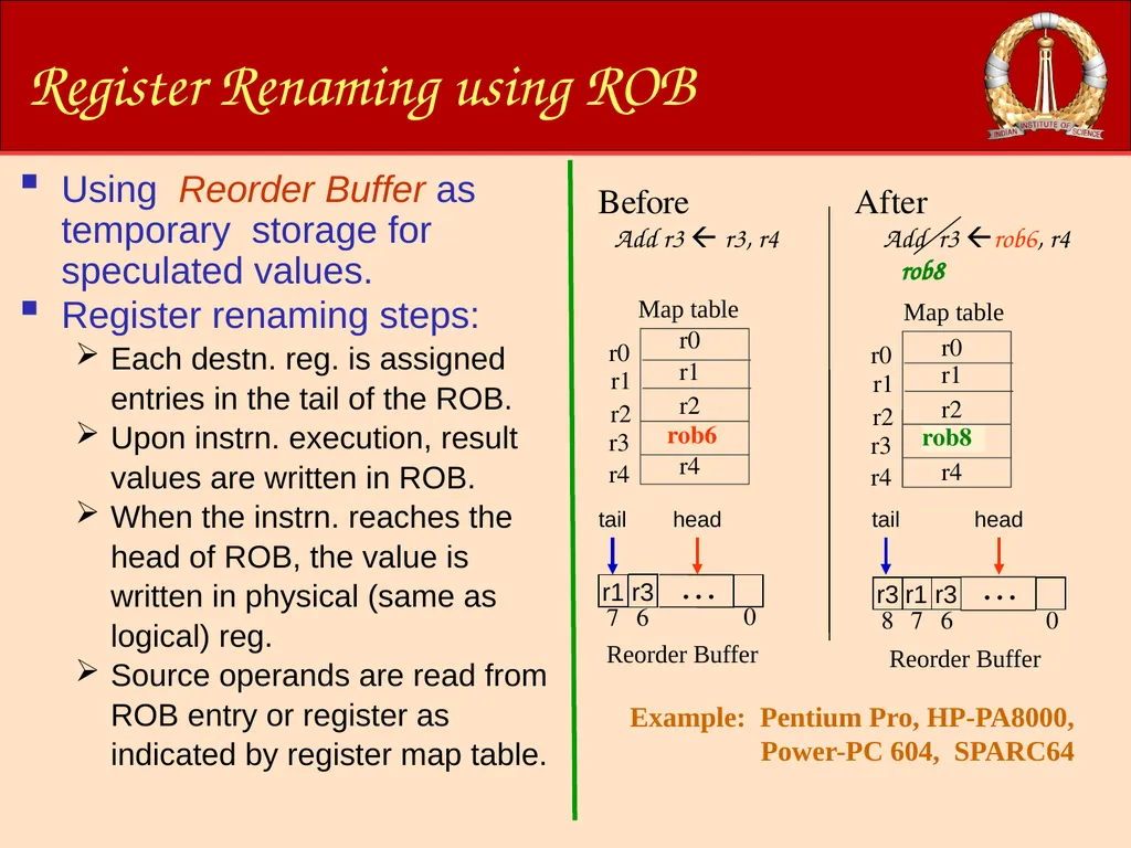
Register Renaming using ROB Using Reorder Buffer as temporary storage for speculated values.
Register renaming steps:
Each destn. reg. is assigned entries in the tail of the ROB.
Upon instrn. execution, result values are written in ROB.
When the instrn. reaches the head of ROB, the value is written in physical (same as logical) reg.
Source operands are read from ROB entry or register as indicated by register map table. Before Add r3 r3, r4 rob6 Map table Reorder Buffer r1 0 r3 7 6 … After 0 r3 8 r3 7 6 Reorder Buffer Add r3 rob6, r4 rob8 rob6 … rob8 r1 head head tail tail<br>
65
ACM-WS 2021
3 Jan. 2022 © RG@CSA, IISc Thank You !!<br>
3 Jan. 2022 © RG@CSA, IISc Thank You !!<br>