
Advanced Wireless Technology Evolution of Wireless





Description: Advanced Wireless Technology Evolution of Wireless Technology Traditional Telephonic System It uses Public Switched Telephone Network (PSTN), also known as Plain Old Telephone Service (POTS) The PSTN relies on circuit switching. The
Related Topics
Download Presentation
"Advanced Wireless Technology Evolution of Wireless" is the property of its rightful owner. Permission is granted to download and print the materials on this website for personal, non-commercial use only, and to display it on your personal computer provided you do not modify the materials and that you retain all copyright notices contained in the materials. By downloading content from our website, you accept the terms of this agreement.
Presentation Transcript
slide1. Advanced Wireless Technology<br>
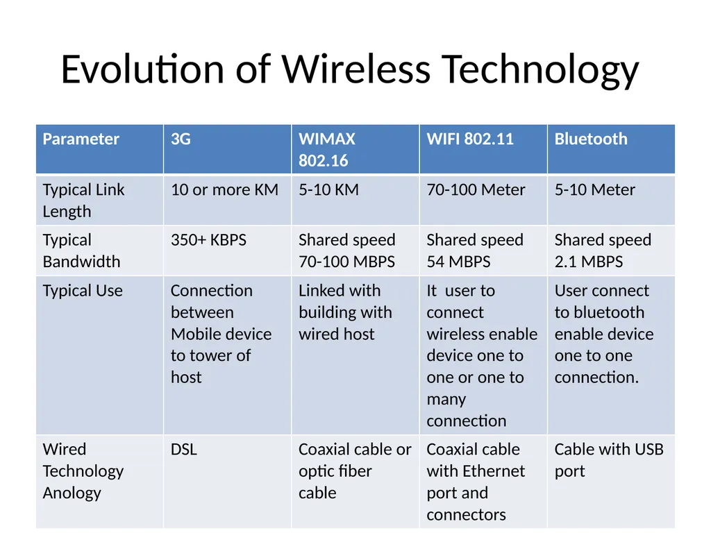
slide2. Evolution of Wireless Technology<br>
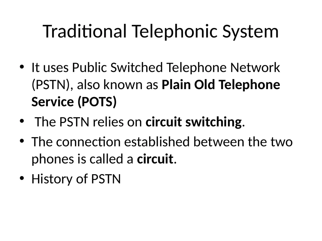
slide3. Traditional Telephonic System It uses Public Switched Telephone Network (PSTN), also known as Plain Old Telephone Service (POTS)
The PSTN relies on circuit switching.
The connection established between the two phones is called a circuit.
History of PSTN<br>
slide4. Working of PSTN The circuit-switched PSTN opens up a continuous connection between two phones, that begins with a dial tone and ends when the phone is hung up.
To start it is required an individual subscriber, or a group of subscribers
Individual subscribers connect directly to the local exchange, while businesses(group) often use a private branch exchange (PBX) to manage all their connections.
The call starts with the actual phone and either connects directly to the Local Exchange or to the PBX and then to the Local Exchange, if the call comes from a business with multiple lines.
From the local exchange network, depending on where the call is going, it is pushed to international carriers, interexchange carriers, cellular providers, or internet service providers.
The number of layers of technology a call passes through varies depending on where the call is destined.<br>
slide5. Components of PSTN The PSTN is comprised of a complex web of interconnection nodes and transmissions links.
There are four different types of nodes: customer premises equipment (CPE), transmission, service, and switching
Transmission links constitute the physical wires or fiber<br>
slide6. CPE:The CPE node is the equipment on site where the call originates. That could be an individual subscriber line or a PBX.
Transmission:
The transmission node consists of the equipment and media that carry information between nodes of a network. This can include things like amplifiers, repeaters, multiplexers, digital cross-connect systems, and digital loop carriers.
Service:
The service node is responsible for signaling. This means determining when to setup, hold, charge, and release connections, and getting that information to the correct outlets that maintain and bill for each section of the network.<br>
slide7. Switches
Local Switches
The Tandem Office (or junction network)
The Toll Office
the International Gateway<br>
slide8. Disadvantages The infrastructure is "older" CAT3 copper wire and can't run high speed data reliably.
The infrastructure was designed to carry 3Khz analog voice
The infrastructure has been spliced and patched back together over the years.
It's extremely expensive to replace it.
Subject to outages from things like falling trees, which cellular service is not.
Doesn't support mobility.<br>
slide9. VOIP Voice over Internet Protocol (VoIP) is a technology that enables one to make and receive phone calls through the Internet instead of using the traditional analogy PSTN (Public Switched Telephone Network) lines.
VoIP services convert your voice into a digital signal that travels over the Internet.
VoIP is packetisation and transport of audio over an IP network
It allows 2-way voice transmission over broadband connection.
It is also called IP telephony, internet telephony, voice over broadband, broadband telephony.<br>
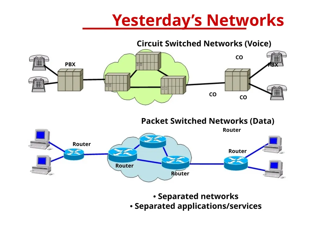
slide10. PBX Yesterday’s Networks Circuit Switched Networks (Voice) CO PBX CO CO Packet Switched Networks (Data) Router Router Router Router Router • Separated networks • Separated applications/services<br>
slide11. Need of VOIP Circuit switching technique: It is used to transfer voice data using ISDN , public telephonic system.
In circuit switching there is dedicated path between source and destination with small in size and fixed bandwidth n/w having delay in transmission.
It uses simple encoding algorithm but sometimes it provides unsatisfied services also it cannot shared by another user due to dedicated channel.
In packet switching , the actual data can be split up into the various packet with destination address.
In this technique store and forward switching is used with statistical multiplexing but this technique is used when data is non voice and gives poor performance when data is voice.
So for that VOIP is invented.
It helps to transfer voice data with packet switching technique.
It is used to provide/improve the packet switching n/w with maintaining the quality of circuit switching.<br>
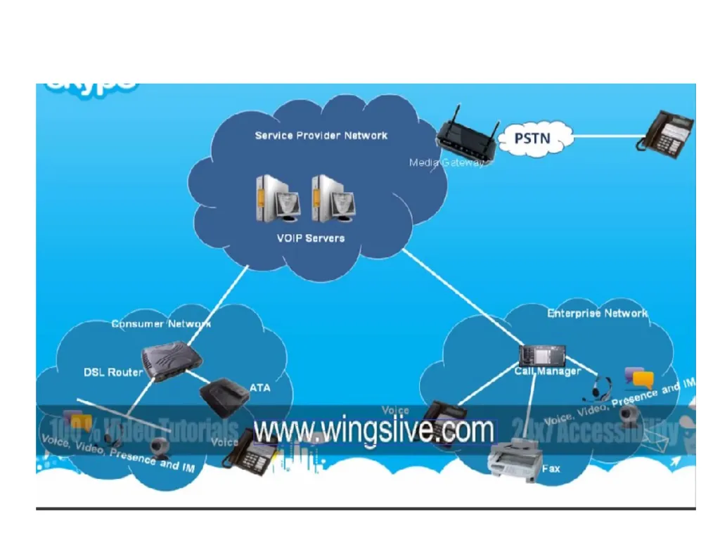
slide12. Architecture of VOIP VOIP is cheaper way of communication over the internet.
It requires broadband internet connection,
VOIP router , and VOIP gateways.<br>
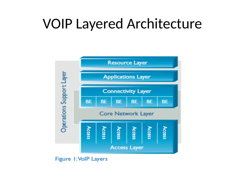
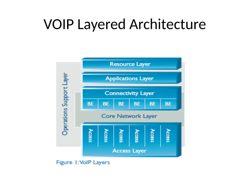
slide14. VOIP Layered Architecture<br>
slide15. VOIP Architecture VoIP layered architecture is to provide a single, common, and shared infrastructure that provides the development of real-time services with the highest quality and availability, the shortest possible time-to-market, and the lowest cost of operations and feasible maintenance.
The architecture is divided into separate independent layers. Each layer follows data hiding i.e. each layer has a well-defined role and provides a set of capabilities for the layer immediately above it by utilizing the set of capabilities provided to it by the layer immediately below it.<br>
slide16. Access Layer The Access Layer provides connectivity between the Customer Premises Equipment (CPE) and the BEs.
Access Layer must support the end-users service requirements such as Quality of Service (QoS), Security, and Availability.
It allows VOIP to provide service that are independent of access technologies i.e.
In the past, new access technologies were managed differently. With this architecture, new access technologies will be deployed quickly and efficiently without disturbing the existing VoIP infrastructure.<br>
slide17. Access Methods Customers in large enterprise locations can be economically served with dedicated access
(Leased Line, FR,ATM, etc)
customers in home offices and small branch offices need to be served by shared access methods (ILEC Local Service, Cable Modem, DSL, etc)
For this access Layer is composed of a variety of access methods<br>
slide18. Access Methods TDM via Edge Switching
TDM Direct Access
TDM via IP Direct Access
IP MIS (Managed Router)
IP Broadband Agnostic
IP Peering<br>
slide19. TDM via Edge Switching:
Customer access occurs via edge switches.
This includes shared access to the ILEC (Incubent local exchanger carrier) and dedicated access to 4E or 5E switches.
The Edge switches could support an IP interface, eliminating the need for TDM to IP conversion in the BE.<br>
slide20. TDM Direct Access – Customer PBX or ILEC switches could interface directly to a Network Gateway BE.
Full range of protocol SS7, ISDN, CAS signaling needs to be supported<br>
slide21. TDM via IP Direct Access (Managed Router/Gateway) – A direct-access line shared with an IP Data Service, (e.g. MIS, MDNS, MRS, EVPN) in conjunction with a VoIP Gateway and CPE Managed Router
It is used to provide a TDM service separation on the customer’s premises.<br>
slide22. IP MIS (Managed Router) – A direct-access line shared with an IP Data Service, (e.g. MIS, MDNS, MRS,EVPN) in conjunction with a CPE Managed Router.
IP Broadband Agnostic –
Customer-purchased Broadband Access, (e.g. Cable, DSL) in conjunction with an Terminal Adapter, It is used to provide Remote Office or second-line service to individual end users. End user devices can be SIP Phones, SIP Clients, Black Phones or other IP devices. QoS is achieved by queuing mechanisms implemented in the Terminal Adapter. Privacy is achieved by IPSec sessions between the Terminal Adapter and BEs.
IP Peering – It provides or purchases VoIP minutes over an IP Interconnect with another VoIP carrier.
Currently, the VoIP signaling protocol is H.323.<br>
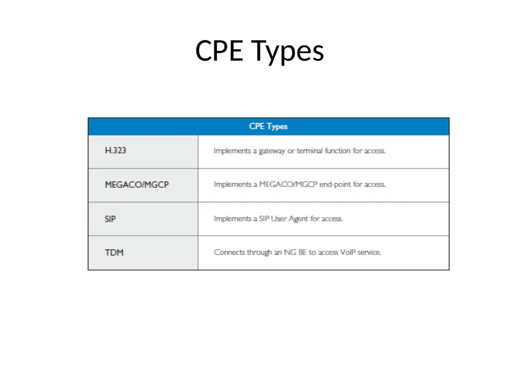
slide23. Customer Premises Equipment CPE are end-point VoIP devices at customer locations where call is initiated. E.g. gateways, IP PBXs, and IP phones
CPE Functional Components
Signaling – It makes interface with standard protocols such as H.323, MGCP, MEGACO, SIP. CPE are typically the end point devices for originating or terminating signaling .
Media Control – CPE terminate the media streams going in and out of the Connectivity Layer and provide final media format conversion<br>
slide24. CPE Types<br>
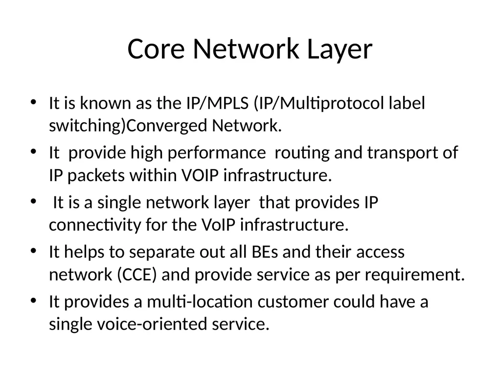
slide25. Core Network Layer It is known as the IP/MPLS (IP/Multiprotocol label switching)Converged Network.
It provide high performance routing and transport of IP packets within VOIP infrastructure.
It is a single network layer that provides IP connectivity for the VoIP infrastructure.
It helps to separate out all BEs and their access network (CCE) and provide service as per requirement.
It provides a multi-location customer could have a single voice-oriented service.<br>
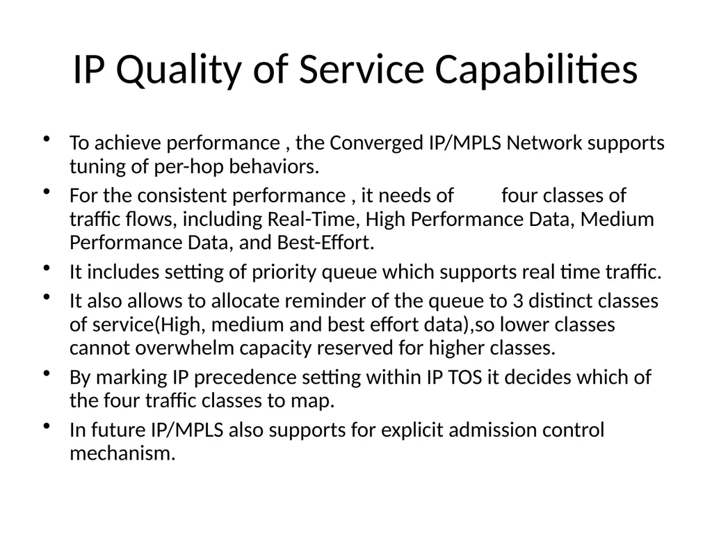
slide26. IP Quality of Service Capabilities To achieve performance , the Converged IP/MPLS Network supports tuning of per-hop behaviors.
For the consistent performance , it needs of four classes of traffic flows, including Real-Time, High Performance Data, Medium Performance Data, and Best-Effort.
It includes setting of priority queue which supports real time traffic.
It also allows to allocate reminder of the queue to 3 distinct classes of service(High, medium and best effort data),so lower classes cannot overwhelm capacity reserved for higher classes.
By marking IP precedence setting within IP TOS it decides which of the four traffic classes to map.
In future IP/MPLS also supports for explicit admission control mechanism.<br>
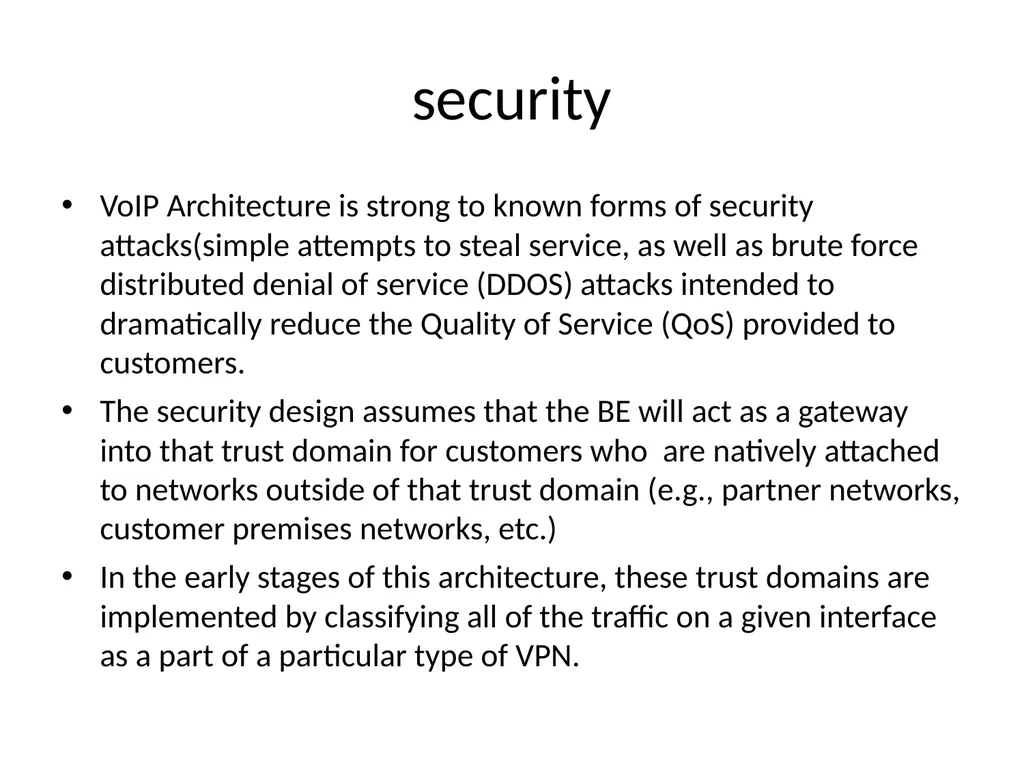
slide27. security VoIP Architecture is strong to known forms of security attacks(simple attempts to steal service, as well as brute force distributed denial of service (DDOS) attacks intended to dramatically reduce the Quality of Service (QoS) provided to customers.
The security design assumes that the BE will act as a gateway into that trust domain for customers who are natively attached to networks outside of that trust domain (e.g., partner networks, customer premises networks, etc.)
In the early stages of this architecture, these trust domains are implemented by classifying all of the traffic on a given interface as a part of a particular type of VPN.<br>
slide28. Connectivity Layer It provides all network primitives needed for application to implement services.
It establishes simple connectivity between end- points by providing capabilities to create, join, remove and report status of call.
Services like E-911,CALEA and call detail recording are enabled in this layer.
It provides a unified, shared environment that supports addition of new services and access technologies without changing basic infrastructure.
This layer consist of no. of zones and collection of network functions.
A zone consist of a CCE that manages one or more Bes.
A network functions and resources are shared by CCEs across many zones.<br>
slide29. Border Element The Border Element (BE) is the point of demarcation/boundary for the Connectivity Layer.
It identifies the Boundary of Trust for the VoIP
Network and provides an entry point into the VoIP infrastructure .
For each customer site , BEs will ensure reliability and availability.
It provides interface between internal address space and the customer site’s address space.
It is responsible for recognizing and authorizing end-points (IP-PBXs, SIP phones, etc.).
Functionally, the BE can be logically decomposed or distributed, if needed.
A configuration is supported in which the media-related processing of the BE takes place at a trusted CPE.<br>
slide30. BE Functional Components Signaling
Media Control
Security
Call Admission Control<br>
slide31. Signaling – A BE proxies both the caller and the called end-points, thereby providing a point of signaling control at the edge.
It translates the access protocol (H.323, MGCP, MEGACO, SS7, CAS, ISDN, etc.) to and from SIP.<br>
slide32. Media Control A BE examines all media streams going in and out of the Connectivity Layer for security, media format conversion, and media transfer.
The BE also redirects media streams upon request from the CCE without impacting the actual caller and called party, and provides the means for the CCE to define, detect and report DTMF strings during the call
Some services require the ability for the AS to detect a signal that does not need to be on the media path(e.g. DTMF, flash hook).e.g. Prepaid card
To enable efficient utilization of network resources, the BE will allow an AS to register event triggers via the CCE, and the BE will signal the AS when the event occurs.<br>
slide33. Security A BE provides all necessary security and screening for the customer sites it interacts with.
authenticates subscribers, customers, and partners, and provides NAT and firewall functions as appropriate.<br>
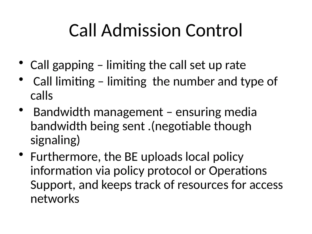
slide34. Call Admission Control Call gapping – limiting the call set up rate
Call limiting – limiting the number and type of calls
Bandwidth management – ensuring media bandwidth being sent .(negotiable though signaling)
Furthermore, the BE uploads local policy information via policy protocol or Operations Support, and keeps track of resources for access networks<br>
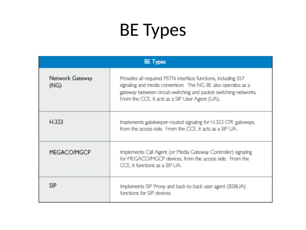
slide35. BE Types<br>
slide36. VOIP Layered Architecture<br>
slide37. CCE It provides call leg analysis of connectivity layer to AS(for example, which dial peer is it? where did it come from?)
Works with the BEs, the CCE completely hides the specifications of the Access and Connectivity Layers from the ASs
It deal with logical end-points (users), call legs, and calls terminating at logical end-points
An AS can ask the CCE to establish a call leg to or from a logical end-point (user), to join call legs to form calls, and to tear down call legs.
The CCE does not need to interact with an AS to serve basic calls with no service features.
The CCE functions as a SIP Back-to-Back User Agent (B2BUA), and is a signaling end-point for all BEs.
Media paths are established directly between BEs without going through CCE.<br>
slide38. Contd… The CCE may receive a “call invocation” (SIP INVITE) from any BE on behalf of a subscriber, or from any server inside the network.
An invocation has information about the caller, the called party, and characteristics of the call(class of service, media type, bandwidth, compression algorithm, etc.).
The CCE may instruct a BE to redirect the media channels associated with a call to a different destination.
A CCE manages all BEs in its zone. It is aware of the status of each BE it manages, including whether the BE is operational or congested.
The CCE enforces various routing policies, such as deciding which BE to
use to set up a call leg.
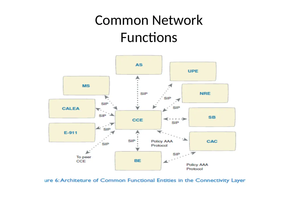
The CCE interacts with the Service Broker (SB), the Network Routing Engine, (NRE), the User Profile Engine (UPE), and the Call Admission Control (CAC).
The CCE also communicates with the resource servers residing in the Connectivity Layer, such as MS, E-911, and CALEA.<br>
slide39. Service Broker Service Broker (SB) maintains subscribers’ service information from a database of installed and activated services.
This database can be shared with other functional entities, such as the NRE and the UPE
The SB acts as the SIP Redirect server and provides tables that define the services subscribed by each individual user.
The SB also performs service precedence and identifies to the CCE which are the primary applicable AS and a list of other services applicable to the call.<br>
slide40. The CCE interacts with the SB The CCE interacts with the SB to determine the services associated with a call leg (either in-bound or out-bound).
For each call, the CCE provides relevant information and requests the AS to execute the corresponding service logic<br>
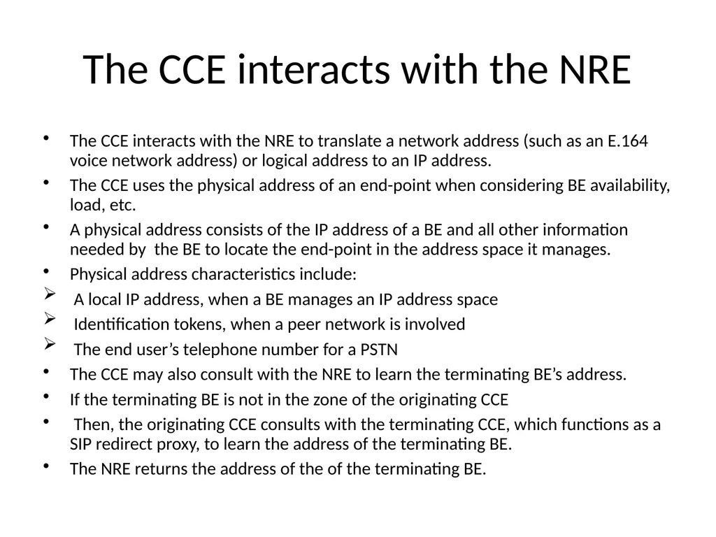
slide41. The CCE interacts with the NRE The CCE interacts with the NRE to translate a network address (such as an E.164 voice network address) or logical address to an IP address.
The CCE uses the physical address of an end-point when considering BE availability, load, etc.
A physical address consists of the IP address of a BE and all other information needed by the BE to locate the end-point in the address space it manages.
Physical address characteristics include:
A local IP address, when a BE manages an IP address space
Identification tokens, when a peer network is involved
The end user’s telephone number for a PSTN
The CCE may also consult with the NRE to learn the terminating BE’s address.
If the terminating BE is not in the zone of the originating CCE
Then, the originating CCE consults with the terminating CCE, which functions as a SIP redirect proxy, to learn the address of the terminating BE.
The NRE returns the address of the of the terminating BE.<br>
slide42. The CCE interacts with the UPE The CCE interacts with the UPE to determine if a user is registered or logged-on, and to determine which address or number should be used to route the call.<br>
slide43. Common Network Functions<br>
slide44. The CCE interacts with the CAC The CCE interacts with the CAC to authorize users and admit calls at the time of call setup, which influences network-wide conditions and policies.
The CCE formulates the QoS/Bandwidth/SLA policy for network-wide resources in conjunction with the local policy and customer-specific requirements provided by the BE.
QoS ensured before acceptance of the call (e.g., ringing will not be provided unless resources have been reserved).<br>
slide45. Network Routing Engine The Network Routing Engine (NRE) provides the route information, upon finding the destination BE.
This route information is required to set up the call leg between the source and destination BEs.
SIP is used between the CCE and the NRE, with the NRE acting as the SIP Redirect server.
NRE database consist of a list of BEs through which user can be reached.
Location server in NRE uses the same database, it collects route information from the PSTN/TDM-IP gateway.
PSTN-IP may be part of BE while TDM-IP gateway is part of CPE.
following protocols are used:
TRIP-GW registration protocol is used by the gateways to register and transfer the route information from the gateway to the Location Server (LS)
2. I-TRIP protocol is used between the NRE and the LS, and between the LSs within the network
3. TRIP protocol is used between the LSs of Network and network partner or other service provider network<br>
slide46. Call Admission Control CAC functional entities help the CCE determine whether to admit or reject a call request.
These functional entities include the Policy Server and the Authentication, Authorization and Accounting (AAA) server
CAC engaged at the time of call setup considers network-wide conditions and policies.
The CAC manages capacity, controls congestion, observes firewall restrictions, and interprets SLA, QoS, Network Address Translation (NAT), and security policies.
The CAC acts as a centralized function controlled by the CCE in collaboration with the BEs<br>
slide47. Policy Server The Policy Server is used primarily for SLA and QoS policies.
This server may also be used for security, accounting, billing, firewall, and NATs.
The policy protocol used between the Policy Server and other functional entities (e.g., CCE, AAA Server, or BE)<br>
slide48. Authentication , Authorization and Accounting (AAA) Server It receives authentication from the BE and uploads security policy.
The AAA protocol used between the AAA server and other functional entities (e.g., CCE or BE)<br>
slide49. User Profile Engine The User Profile Engine (UPE) is a functional entity that keeps both static and dynamic user profiles.
The UPE consists of a SIP Registration server and a Presence Server (future implementation), which, along with the NRE, share the same logical database.
Access to the UPE is controlled by the CCE using SIP signaling messages.
The Registration Server receives SIP registration requests under the control of the CCE, via BEs.
The user location information obtained from the registration messages is updated into the user profile database.
Users who subscribe to services will register with this server under the control of the CCE, via BEs.
The Presence Server stores and conveys the user’s location and status (e.g., offline, busy,other).
Users will register with the Presence Server (PS) under the control of the CCE, via BEs.
The PS will subscribe to the users’ presence information.
When a status changes, (e.g., online, offline, busy) notifications will be sent by users’ presence agents and immediately update the PS.
User’s availability should map to presence information so that the call can be routed to the address where the user is currently available.<br>
slide50. Media Servers Media Servers (MS) typically operate with ASs to handle and terminate media streams, and to provide services
such as announcements, bridges, transcoding, and Interactive Voice Response (IVR) messages.
Using SIP to communicate, the AS sends an invite to the MS, via the CCE, setting up the call and specifying the script which the MS executes or the function it performs.
The MS returns the status and results to the AS via HTTP posts.
Only Network Gatewsy BEs provide network-busy announcements ,remaining components of this architecture will not provide their own MS functions.<br>
slide51. Call Detail Recording Call Detail Recording is required to provide data for billing and operations. The target is to have all BEs, CCEs, and ASs generate Call Detail Records (CDRs) for Operations Support, and to have the CCE generate an integrated CDR for billing purposes.
The BEs and ASs should send the required information for billing to the CCE, via call signaling.
There are several key requirements that will enable state-of-the-art network management and billing:
Near-real time delivery to traffic monitoring, fraud detection, and billing systems
Vendor-independent formats based on industry or standards-based formats
Inclusion of quality of call and routing information
4. Capturing PSTN interconnection and termination release codes
5. Capturing a Unique Call ID from the originating BE
6. Clearly-defined audit methods
7. Record storage and redelivery in the case of lost connectivity<br>
slide52. Application layer AS provides common interface to the VoIP Connectivity Layer.
It provides two facilities-
Plug in
Service Creation.<br>
slide53. Plug In It facilitates fast and easy addition of new features.
An AS implements new feature “plug-ins” without having to introduce new capabilities or protocols to the core VoIP Architecture.<br>
slide54. Service Creation. Many ASs implement specific service logic as defined by the vendor, certain ASs will instead serve as software platforms for implementing new services.
These ASs have two elements:
Service Creation Environment(SCE)
Service Logic Execution Environment (SLEE).<br>
slide55. SCE The Service Creation Environment (SCE) allows a development team to develop and test new service logic scripts(it consist of many building blocks).
The Service Logic Execution Environment (SLEE) provides the run-time environment for executing service logic scripts.<br>
slide56. Resource Layer The Resource Layer contains all systems that various ASs may use to provide their services
Most of these resources are owned and operated by vendor but a few may be owned and operated by customers.
Protocols are not defined as a part of this architecture.<br>
slide57. Operational Support Layer The Operations Support Layer consists of multiple applications, databases, and a supporting data communications network used by internal and external personnel to manage the VoIP network and its elements.
Fault Management, Configuration Management, Network and Service Provisioning, Capacity Management, and Performance and Incident Management are different operational support services.
It relies on following designs
Concept of one
Zero touch
E-enablement
Open standard.<br>
slide58. Advantages of VOIP It is cheaper way of communication.
Simple and upgrading is also simple
Voip Pc –pc is free and pc-phone charges are nominal.
For monthly fee free call can be made within geographic area.
Virtual number enables user to make call anywhere as a broadband connection is available.
Calling and messaging are done at the same time with voip.
Replace expensive tie lines.<br>
slide59. Disadvantages of VOIP Loss of service during outing.
It requires power.
With voip emergency, call it is difficult to locate user.
Some times data may be lost.
No standard protocol is applicable.<br>
slide60. Applications Office to office communication
Off net calling.
Create off premise extension.
Dial system with VOIP.
Video calling over internet.<br>
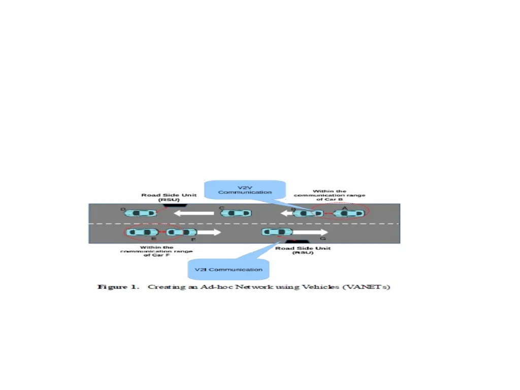
slide61. VANET Vehicular ad-hoc networks (VANETs) technology.
Vehicular ad-hoc networks are responsible for the
communication between moving vehicles in a certain environment.
It is created from the concept of establishing a network of cars for a specific need or situation.
established as reliable networks that vehicles use for communication purpose on highways or urban environments<br>
slide63. Characteristics High mobility of nodes
Rapidly changing network topology (predictable to some extent)
Unbounded network size
Potential support from infrastructure
Real-time, time-sensitive data exchange
Crucial effect of security and privacy<br>
slide64. Architecture there is no fixed architecture or topology that
a VANET must follow.
VANET consist of AU,OBU and RSU
VANET consist of 3 domains
In-vehicle Domain
Adhoc Domain
Infrastructure Domain.<br>
slide65. In-vehicle Domain: It consist of OBU and AU inside the vehicle.AU executes application by using communication capabilities of OBU.
An OBU is at least equipped dedicated for road safety.
AU and OBU are logical and they can also reside in a single physical unit
Adhoc Domain: it is composed with vehicle equipped with OBU and RSUs
OBU allows communication among nodes without need of centralized coordination instance.
OBUs directly communicate if wireless connectivity exist and uses multi-hop communication for data forwarding.<br>
slide66. Infrastructure Domain: It consist of RSU and wireless hotspots(HT) access for safety and non safety applications.
RSU for internet access are set up by road administrator or public authority.
OBUs can utilize communication capabilities of cellular radio n/w<br>
slide67. Application Unit It is in-vehicle entity and uses communication capabilities of OBU.
Multiple Aus can be plugged in with a single on board Unit simultaneously and share OBUs processing and wireless resources.
An AU communicates with OBU solely which handle all mobility and networking functions.
E.g.a dedicated device for safety application like hazard warning.
A navigation system with communication capabilities.<br>
slide68. On-Board Unit It is used for V2V and V2I communication.
It also provides communication services to AUs and forward data on behalf of other OBUs in adhoc domain
An OBU is equipped with at least a single network device for short range wireless communication based on IEEE 802.11p radio tech.
This n/w device is used to send , receive and forward safety related data in the ad hoc domain.
An OBU can be equipped with more n/w devices based on IEEE 802.11va/b/g/n
It includes functionality like wireless radio access, geographical adhoc routing, n/w congestion control ,reliable message transfer , data security, IP mobility support etc.<br>
slide69. RSU It is physical device located at fixed position along roads and highways, or at dedicated locations such as gas stations, parking places and restaurant.
It includes following functionalities
Extending communication range of an adhoc network by means of re-distribution of info. to other OBUs and cooperating with other RSU in forwarding or redistributing safety info.
Running safety applications such as for V2I warning and acts as info. Source and destination resply.
Providing internet connectivity to OBUs.<br>
slide70. WAVE It is wireless access to vehicular environment.
It is subset of short range communication.
IEEE 802.11p radio technology defined for it
It’s objective is to give relation between application in vehicle and wireless device which is in rapidly varying environment.
The exchange of info. is finished in extremly little time duration.
It uses multiple channel i.e. europe uses frequency of 5.8/5.9 GHZ with lookout mobile from 5.850 -5.855 GHZ<br>
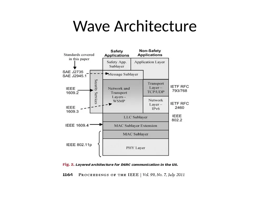
slide71. Wave Architecture<br>
slide72. The PHY and MAC layers utilizes IEEE 802.11p standard
At first MAC address are allocated to a random value, when OBU receives message from one more OBU or RSU then original MAC address is assigned.
MAC layer also implements IEEE P1609.4 –multichannel operation standard and it decides the performance of MAC layer on the available CCH and SCH.
The messages are transmitted using wave short message protocol(WSMP)
WSMP utilizes the non IP based applications and uses higher priority communication.
The block which sends WAVE short message protocol is known as a provider.
The channel at the ending boundaries are reserved to avoid accidents.
Channel 178 is the control channel and used to send emergency message and the remaining ones are service channel used to send regular channel<br>
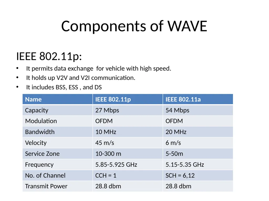
slide73. Components of WAVE IEEE 802.11p:
It permits data exchange for vehicle with high speed.
It holds up V2V and V2I communication.
It includes BSS, ESS , and DS<br>
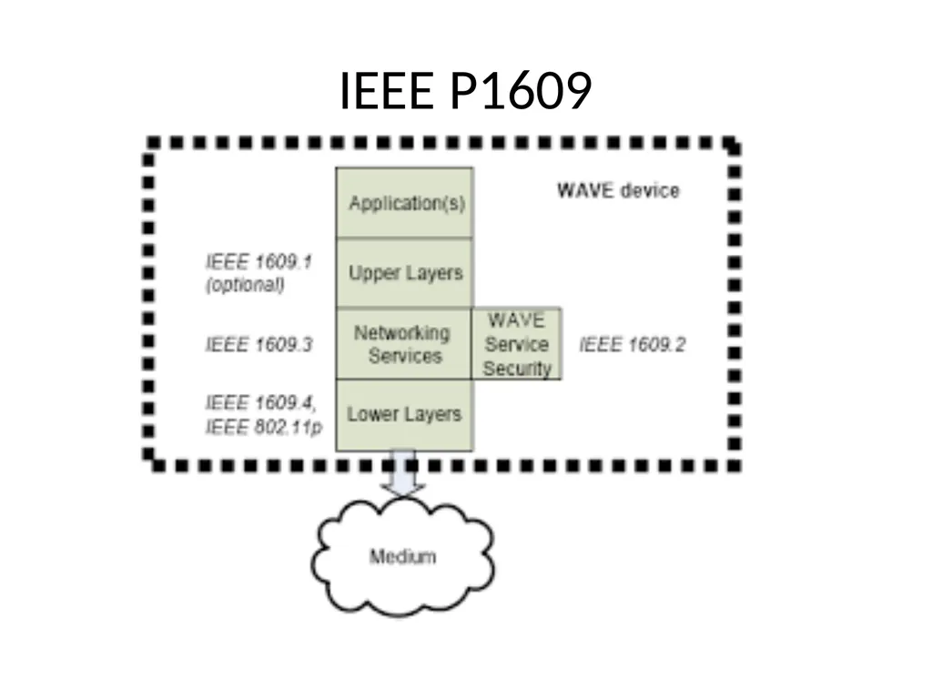
slide74. IEEE P1609<br>
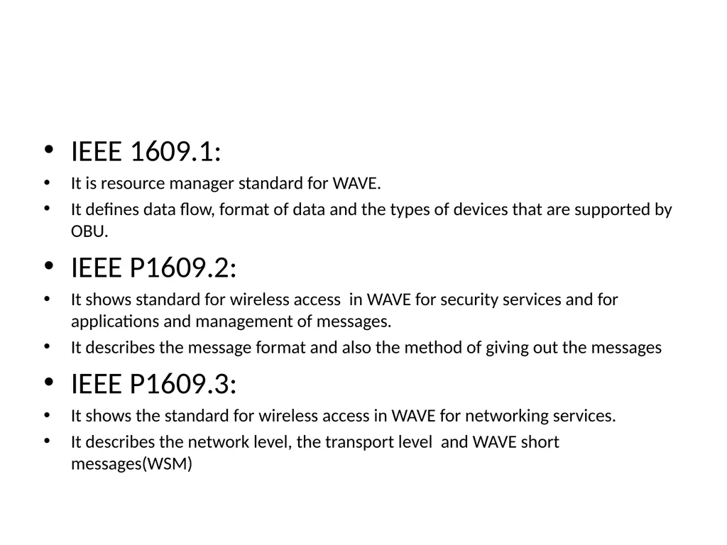
slide75. IEEE 1609.1:
It is resource manager standard for WAVE.
It defines data flow, format of data and the types of devices that are supported by OBU.
IEEE P1609.2:
It shows standard for wireless access in WAVE for security services and for applications and management of messages.
It describes the message format and also the method of giving out the messages
IEEE P1609.3:
It shows the standard for wireless access in WAVE for networking services.
It describes the network level, the transport level and WAVE short messages(WSM)<br>
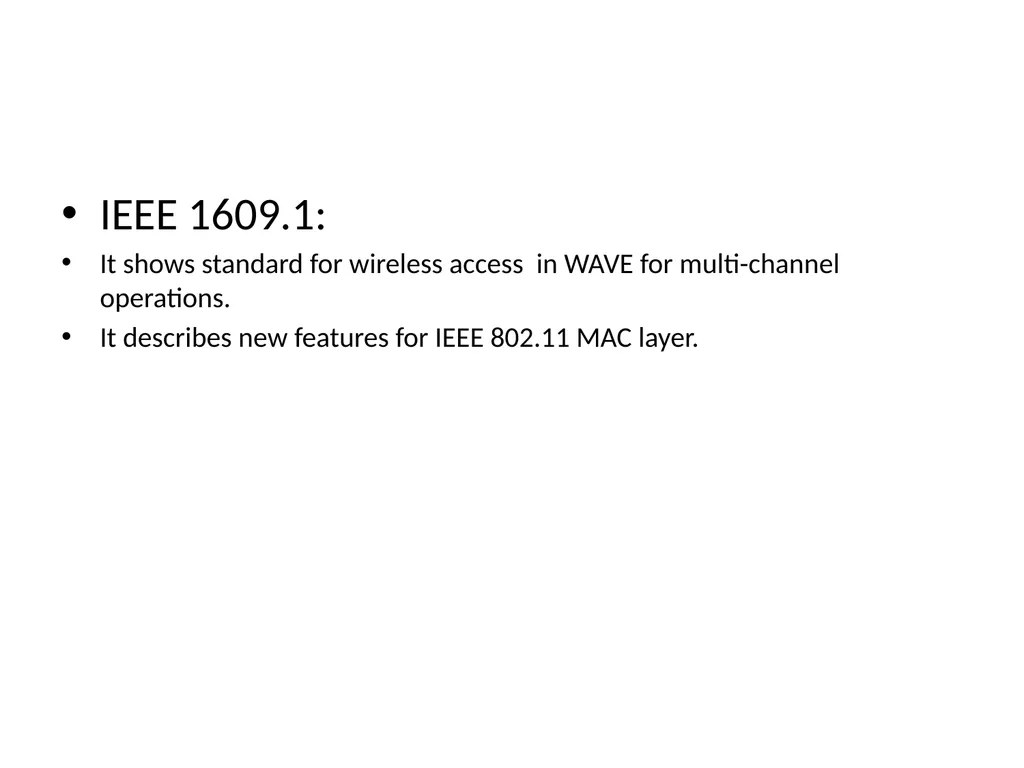
slide76. IEEE 1609.1:
It shows standard for wireless access in WAVE for multi-channel operations.
It describes new features for IEEE 802.11 MAC layer.<br>
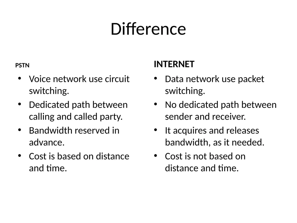
slide78. Difference PSTN Voice network use circuit switching.
Dedicated path between calling and called party.
Bandwidth reserved in advance.
Cost is based on distance and time. INTERNET Data network use packet switching.
No dedicated path between sender and receiver.
It acquires and releases bandwidth, as it needed.
Cost is not based on distance and time.<br>
slide2. Evolution of Wireless Technology<br>
slide3. Traditional Telephonic System It uses Public Switched Telephone Network (PSTN), also known as Plain Old Telephone Service (POTS)
The PSTN relies on circuit switching.
The connection established between the two phones is called a circuit.
History of PSTN<br>
slide4. Working of PSTN The circuit-switched PSTN opens up a continuous connection between two phones, that begins with a dial tone and ends when the phone is hung up.
To start it is required an individual subscriber, or a group of subscribers
Individual subscribers connect directly to the local exchange, while businesses(group) often use a private branch exchange (PBX) to manage all their connections.
The call starts with the actual phone and either connects directly to the Local Exchange or to the PBX and then to the Local Exchange, if the call comes from a business with multiple lines.
From the local exchange network, depending on where the call is going, it is pushed to international carriers, interexchange carriers, cellular providers, or internet service providers.
The number of layers of technology a call passes through varies depending on where the call is destined.<br>
slide5. Components of PSTN The PSTN is comprised of a complex web of interconnection nodes and transmissions links.
There are four different types of nodes: customer premises equipment (CPE), transmission, service, and switching
Transmission links constitute the physical wires or fiber<br>
slide6. CPE:The CPE node is the equipment on site where the call originates. That could be an individual subscriber line or a PBX.
Transmission:
The transmission node consists of the equipment and media that carry information between nodes of a network. This can include things like amplifiers, repeaters, multiplexers, digital cross-connect systems, and digital loop carriers.
Service:
The service node is responsible for signaling. This means determining when to setup, hold, charge, and release connections, and getting that information to the correct outlets that maintain and bill for each section of the network.<br>
slide7. Switches
Local Switches
The Tandem Office (or junction network)
The Toll Office
the International Gateway<br>
slide8. Disadvantages The infrastructure is "older" CAT3 copper wire and can't run high speed data reliably.
The infrastructure was designed to carry 3Khz analog voice
The infrastructure has been spliced and patched back together over the years.
It's extremely expensive to replace it.
Subject to outages from things like falling trees, which cellular service is not.
Doesn't support mobility.<br>
slide9. VOIP Voice over Internet Protocol (VoIP) is a technology that enables one to make and receive phone calls through the Internet instead of using the traditional analogy PSTN (Public Switched Telephone Network) lines.
VoIP services convert your voice into a digital signal that travels over the Internet.
VoIP is packetisation and transport of audio over an IP network
It allows 2-way voice transmission over broadband connection.
It is also called IP telephony, internet telephony, voice over broadband, broadband telephony.<br>
slide10. PBX Yesterday’s Networks Circuit Switched Networks (Voice) CO PBX CO CO Packet Switched Networks (Data) Router Router Router Router Router • Separated networks • Separated applications/services<br>
slide11. Need of VOIP Circuit switching technique: It is used to transfer voice data using ISDN , public telephonic system.
In circuit switching there is dedicated path between source and destination with small in size and fixed bandwidth n/w having delay in transmission.
It uses simple encoding algorithm but sometimes it provides unsatisfied services also it cannot shared by another user due to dedicated channel.
In packet switching , the actual data can be split up into the various packet with destination address.
In this technique store and forward switching is used with statistical multiplexing but this technique is used when data is non voice and gives poor performance when data is voice.
So for that VOIP is invented.
It helps to transfer voice data with packet switching technique.
It is used to provide/improve the packet switching n/w with maintaining the quality of circuit switching.<br>
slide12. Architecture of VOIP VOIP is cheaper way of communication over the internet.
It requires broadband internet connection,
VOIP router , and VOIP gateways.<br>
slide14. VOIP Layered Architecture<br>
slide15. VOIP Architecture VoIP layered architecture is to provide a single, common, and shared infrastructure that provides the development of real-time services with the highest quality and availability, the shortest possible time-to-market, and the lowest cost of operations and feasible maintenance.
The architecture is divided into separate independent layers. Each layer follows data hiding i.e. each layer has a well-defined role and provides a set of capabilities for the layer immediately above it by utilizing the set of capabilities provided to it by the layer immediately below it.<br>
slide16. Access Layer The Access Layer provides connectivity between the Customer Premises Equipment (CPE) and the BEs.
Access Layer must support the end-users service requirements such as Quality of Service (QoS), Security, and Availability.
It allows VOIP to provide service that are independent of access technologies i.e.
In the past, new access technologies were managed differently. With this architecture, new access technologies will be deployed quickly and efficiently without disturbing the existing VoIP infrastructure.<br>
slide17. Access Methods Customers in large enterprise locations can be economically served with dedicated access
(Leased Line, FR,ATM, etc)
customers in home offices and small branch offices need to be served by shared access methods (ILEC Local Service, Cable Modem, DSL, etc)
For this access Layer is composed of a variety of access methods<br>
slide18. Access Methods TDM via Edge Switching
TDM Direct Access
TDM via IP Direct Access
IP MIS (Managed Router)
IP Broadband Agnostic
IP Peering<br>
slide19. TDM via Edge Switching:
Customer access occurs via edge switches.
This includes shared access to the ILEC (Incubent local exchanger carrier) and dedicated access to 4E or 5E switches.
The Edge switches could support an IP interface, eliminating the need for TDM to IP conversion in the BE.<br>
slide20. TDM Direct Access – Customer PBX or ILEC switches could interface directly to a Network Gateway BE.
Full range of protocol SS7, ISDN, CAS signaling needs to be supported<br>
slide21. TDM via IP Direct Access (Managed Router/Gateway) – A direct-access line shared with an IP Data Service, (e.g. MIS, MDNS, MRS, EVPN) in conjunction with a VoIP Gateway and CPE Managed Router
It is used to provide a TDM service separation on the customer’s premises.<br>
slide22. IP MIS (Managed Router) – A direct-access line shared with an IP Data Service, (e.g. MIS, MDNS, MRS,EVPN) in conjunction with a CPE Managed Router.
IP Broadband Agnostic –
Customer-purchased Broadband Access, (e.g. Cable, DSL) in conjunction with an Terminal Adapter, It is used to provide Remote Office or second-line service to individual end users. End user devices can be SIP Phones, SIP Clients, Black Phones or other IP devices. QoS is achieved by queuing mechanisms implemented in the Terminal Adapter. Privacy is achieved by IPSec sessions between the Terminal Adapter and BEs.
IP Peering – It provides or purchases VoIP minutes over an IP Interconnect with another VoIP carrier.
Currently, the VoIP signaling protocol is H.323.<br>
slide23. Customer Premises Equipment CPE are end-point VoIP devices at customer locations where call is initiated. E.g. gateways, IP PBXs, and IP phones
CPE Functional Components
Signaling – It makes interface with standard protocols such as H.323, MGCP, MEGACO, SIP. CPE are typically the end point devices for originating or terminating signaling .
Media Control – CPE terminate the media streams going in and out of the Connectivity Layer and provide final media format conversion<br>
slide24. CPE Types<br>
slide25. Core Network Layer It is known as the IP/MPLS (IP/Multiprotocol label switching)Converged Network.
It provide high performance routing and transport of IP packets within VOIP infrastructure.
It is a single network layer that provides IP connectivity for the VoIP infrastructure.
It helps to separate out all BEs and their access network (CCE) and provide service as per requirement.
It provides a multi-location customer could have a single voice-oriented service.<br>
slide26. IP Quality of Service Capabilities To achieve performance , the Converged IP/MPLS Network supports tuning of per-hop behaviors.
For the consistent performance , it needs of four classes of traffic flows, including Real-Time, High Performance Data, Medium Performance Data, and Best-Effort.
It includes setting of priority queue which supports real time traffic.
It also allows to allocate reminder of the queue to 3 distinct classes of service(High, medium and best effort data),so lower classes cannot overwhelm capacity reserved for higher classes.
By marking IP precedence setting within IP TOS it decides which of the four traffic classes to map.
In future IP/MPLS also supports for explicit admission control mechanism.<br>
slide27. security VoIP Architecture is strong to known forms of security attacks(simple attempts to steal service, as well as brute force distributed denial of service (DDOS) attacks intended to dramatically reduce the Quality of Service (QoS) provided to customers.
The security design assumes that the BE will act as a gateway into that trust domain for customers who are natively attached to networks outside of that trust domain (e.g., partner networks, customer premises networks, etc.)
In the early stages of this architecture, these trust domains are implemented by classifying all of the traffic on a given interface as a part of a particular type of VPN.<br>
slide28. Connectivity Layer It provides all network primitives needed for application to implement services.
It establishes simple connectivity between end- points by providing capabilities to create, join, remove and report status of call.
Services like E-911,CALEA and call detail recording are enabled in this layer.
It provides a unified, shared environment that supports addition of new services and access technologies without changing basic infrastructure.
This layer consist of no. of zones and collection of network functions.
A zone consist of a CCE that manages one or more Bes.
A network functions and resources are shared by CCEs across many zones.<br>
slide29. Border Element The Border Element (BE) is the point of demarcation/boundary for the Connectivity Layer.
It identifies the Boundary of Trust for the VoIP
Network and provides an entry point into the VoIP infrastructure .
For each customer site , BEs will ensure reliability and availability.
It provides interface between internal address space and the customer site’s address space.
It is responsible for recognizing and authorizing end-points (IP-PBXs, SIP phones, etc.).
Functionally, the BE can be logically decomposed or distributed, if needed.
A configuration is supported in which the media-related processing of the BE takes place at a trusted CPE.<br>
slide30. BE Functional Components Signaling
Media Control
Security
Call Admission Control<br>
slide31. Signaling – A BE proxies both the caller and the called end-points, thereby providing a point of signaling control at the edge.
It translates the access protocol (H.323, MGCP, MEGACO, SS7, CAS, ISDN, etc.) to and from SIP.<br>
slide32. Media Control A BE examines all media streams going in and out of the Connectivity Layer for security, media format conversion, and media transfer.
The BE also redirects media streams upon request from the CCE without impacting the actual caller and called party, and provides the means for the CCE to define, detect and report DTMF strings during the call
Some services require the ability for the AS to detect a signal that does not need to be on the media path(e.g. DTMF, flash hook).e.g. Prepaid card
To enable efficient utilization of network resources, the BE will allow an AS to register event triggers via the CCE, and the BE will signal the AS when the event occurs.<br>
slide33. Security A BE provides all necessary security and screening for the customer sites it interacts with.
authenticates subscribers, customers, and partners, and provides NAT and firewall functions as appropriate.<br>
slide34. Call Admission Control Call gapping – limiting the call set up rate
Call limiting – limiting the number and type of calls
Bandwidth management – ensuring media bandwidth being sent .(negotiable though signaling)
Furthermore, the BE uploads local policy information via policy protocol or Operations Support, and keeps track of resources for access networks<br>
slide35. BE Types<br>
slide36. VOIP Layered Architecture<br>
slide37. CCE It provides call leg analysis of connectivity layer to AS(for example, which dial peer is it? where did it come from?)
Works with the BEs, the CCE completely hides the specifications of the Access and Connectivity Layers from the ASs
It deal with logical end-points (users), call legs, and calls terminating at logical end-points
An AS can ask the CCE to establish a call leg to or from a logical end-point (user), to join call legs to form calls, and to tear down call legs.
The CCE does not need to interact with an AS to serve basic calls with no service features.
The CCE functions as a SIP Back-to-Back User Agent (B2BUA), and is a signaling end-point for all BEs.
Media paths are established directly between BEs without going through CCE.<br>
slide38. Contd… The CCE may receive a “call invocation” (SIP INVITE) from any BE on behalf of a subscriber, or from any server inside the network.
An invocation has information about the caller, the called party, and characteristics of the call(class of service, media type, bandwidth, compression algorithm, etc.).
The CCE may instruct a BE to redirect the media channels associated with a call to a different destination.
A CCE manages all BEs in its zone. It is aware of the status of each BE it manages, including whether the BE is operational or congested.
The CCE enforces various routing policies, such as deciding which BE to
use to set up a call leg.
The CCE interacts with the Service Broker (SB), the Network Routing Engine, (NRE), the User Profile Engine (UPE), and the Call Admission Control (CAC).
The CCE also communicates with the resource servers residing in the Connectivity Layer, such as MS, E-911, and CALEA.<br>
slide39. Service Broker Service Broker (SB) maintains subscribers’ service information from a database of installed and activated services.
This database can be shared with other functional entities, such as the NRE and the UPE
The SB acts as the SIP Redirect server and provides tables that define the services subscribed by each individual user.
The SB also performs service precedence and identifies to the CCE which are the primary applicable AS and a list of other services applicable to the call.<br>
slide40. The CCE interacts with the SB The CCE interacts with the SB to determine the services associated with a call leg (either in-bound or out-bound).
For each call, the CCE provides relevant information and requests the AS to execute the corresponding service logic<br>
slide41. The CCE interacts with the NRE The CCE interacts with the NRE to translate a network address (such as an E.164 voice network address) or logical address to an IP address.
The CCE uses the physical address of an end-point when considering BE availability, load, etc.
A physical address consists of the IP address of a BE and all other information needed by the BE to locate the end-point in the address space it manages.
Physical address characteristics include:
A local IP address, when a BE manages an IP address space
Identification tokens, when a peer network is involved
The end user’s telephone number for a PSTN
The CCE may also consult with the NRE to learn the terminating BE’s address.
If the terminating BE is not in the zone of the originating CCE
Then, the originating CCE consults with the terminating CCE, which functions as a SIP redirect proxy, to learn the address of the terminating BE.
The NRE returns the address of the of the terminating BE.<br>
slide42. The CCE interacts with the UPE The CCE interacts with the UPE to determine if a user is registered or logged-on, and to determine which address or number should be used to route the call.<br>
slide43. Common Network Functions<br>
slide44. The CCE interacts with the CAC The CCE interacts with the CAC to authorize users and admit calls at the time of call setup, which influences network-wide conditions and policies.
The CCE formulates the QoS/Bandwidth/SLA policy for network-wide resources in conjunction with the local policy and customer-specific requirements provided by the BE.
QoS ensured before acceptance of the call (e.g., ringing will not be provided unless resources have been reserved).<br>
slide45. Network Routing Engine The Network Routing Engine (NRE) provides the route information, upon finding the destination BE.
This route information is required to set up the call leg between the source and destination BEs.
SIP is used between the CCE and the NRE, with the NRE acting as the SIP Redirect server.
NRE database consist of a list of BEs through which user can be reached.
Location server in NRE uses the same database, it collects route information from the PSTN/TDM-IP gateway.
PSTN-IP may be part of BE while TDM-IP gateway is part of CPE.
following protocols are used:
TRIP-GW registration protocol is used by the gateways to register and transfer the route information from the gateway to the Location Server (LS)
2. I-TRIP protocol is used between the NRE and the LS, and between the LSs within the network
3. TRIP protocol is used between the LSs of Network and network partner or other service provider network<br>
slide46. Call Admission Control CAC functional entities help the CCE determine whether to admit or reject a call request.
These functional entities include the Policy Server and the Authentication, Authorization and Accounting (AAA) server
CAC engaged at the time of call setup considers network-wide conditions and policies.
The CAC manages capacity, controls congestion, observes firewall restrictions, and interprets SLA, QoS, Network Address Translation (NAT), and security policies.
The CAC acts as a centralized function controlled by the CCE in collaboration with the BEs<br>
slide47. Policy Server The Policy Server is used primarily for SLA and QoS policies.
This server may also be used for security, accounting, billing, firewall, and NATs.
The policy protocol used between the Policy Server and other functional entities (e.g., CCE, AAA Server, or BE)<br>
slide48. Authentication , Authorization and Accounting (AAA) Server It receives authentication from the BE and uploads security policy.
The AAA protocol used between the AAA server and other functional entities (e.g., CCE or BE)<br>
slide49. User Profile Engine The User Profile Engine (UPE) is a functional entity that keeps both static and dynamic user profiles.
The UPE consists of a SIP Registration server and a Presence Server (future implementation), which, along with the NRE, share the same logical database.
Access to the UPE is controlled by the CCE using SIP signaling messages.
The Registration Server receives SIP registration requests under the control of the CCE, via BEs.
The user location information obtained from the registration messages is updated into the user profile database.
Users who subscribe to services will register with this server under the control of the CCE, via BEs.
The Presence Server stores and conveys the user’s location and status (e.g., offline, busy,other).
Users will register with the Presence Server (PS) under the control of the CCE, via BEs.
The PS will subscribe to the users’ presence information.
When a status changes, (e.g., online, offline, busy) notifications will be sent by users’ presence agents and immediately update the PS.
User’s availability should map to presence information so that the call can be routed to the address where the user is currently available.<br>
slide50. Media Servers Media Servers (MS) typically operate with ASs to handle and terminate media streams, and to provide services
such as announcements, bridges, transcoding, and Interactive Voice Response (IVR) messages.
Using SIP to communicate, the AS sends an invite to the MS, via the CCE, setting up the call and specifying the script which the MS executes or the function it performs.
The MS returns the status and results to the AS via HTTP posts.
Only Network Gatewsy BEs provide network-busy announcements ,remaining components of this architecture will not provide their own MS functions.<br>
slide51. Call Detail Recording Call Detail Recording is required to provide data for billing and operations. The target is to have all BEs, CCEs, and ASs generate Call Detail Records (CDRs) for Operations Support, and to have the CCE generate an integrated CDR for billing purposes.
The BEs and ASs should send the required information for billing to the CCE, via call signaling.
There are several key requirements that will enable state-of-the-art network management and billing:
Near-real time delivery to traffic monitoring, fraud detection, and billing systems
Vendor-independent formats based on industry or standards-based formats
Inclusion of quality of call and routing information
4. Capturing PSTN interconnection and termination release codes
5. Capturing a Unique Call ID from the originating BE
6. Clearly-defined audit methods
7. Record storage and redelivery in the case of lost connectivity<br>
slide52. Application layer AS provides common interface to the VoIP Connectivity Layer.
It provides two facilities-
Plug in
Service Creation.<br>
slide53. Plug In It facilitates fast and easy addition of new features.
An AS implements new feature “plug-ins” without having to introduce new capabilities or protocols to the core VoIP Architecture.<br>
slide54. Service Creation. Many ASs implement specific service logic as defined by the vendor, certain ASs will instead serve as software platforms for implementing new services.
These ASs have two elements:
Service Creation Environment(SCE)
Service Logic Execution Environment (SLEE).<br>
slide55. SCE The Service Creation Environment (SCE) allows a development team to develop and test new service logic scripts(it consist of many building blocks).
The Service Logic Execution Environment (SLEE) provides the run-time environment for executing service logic scripts.<br>
slide56. Resource Layer The Resource Layer contains all systems that various ASs may use to provide their services
Most of these resources are owned and operated by vendor but a few may be owned and operated by customers.
Protocols are not defined as a part of this architecture.<br>
slide57. Operational Support Layer The Operations Support Layer consists of multiple applications, databases, and a supporting data communications network used by internal and external personnel to manage the VoIP network and its elements.
Fault Management, Configuration Management, Network and Service Provisioning, Capacity Management, and Performance and Incident Management are different operational support services.
It relies on following designs
Concept of one
Zero touch
E-enablement
Open standard.<br>
slide58. Advantages of VOIP It is cheaper way of communication.
Simple and upgrading is also simple
Voip Pc –pc is free and pc-phone charges are nominal.
For monthly fee free call can be made within geographic area.
Virtual number enables user to make call anywhere as a broadband connection is available.
Calling and messaging are done at the same time with voip.
Replace expensive tie lines.<br>
slide59. Disadvantages of VOIP Loss of service during outing.
It requires power.
With voip emergency, call it is difficult to locate user.
Some times data may be lost.
No standard protocol is applicable.<br>
slide60. Applications Office to office communication
Off net calling.
Create off premise extension.
Dial system with VOIP.
Video calling over internet.<br>
slide61. VANET Vehicular ad-hoc networks (VANETs) technology.
Vehicular ad-hoc networks are responsible for the
communication between moving vehicles in a certain environment.
It is created from the concept of establishing a network of cars for a specific need or situation.
established as reliable networks that vehicles use for communication purpose on highways or urban environments<br>
slide63. Characteristics High mobility of nodes
Rapidly changing network topology (predictable to some extent)
Unbounded network size
Potential support from infrastructure
Real-time, time-sensitive data exchange
Crucial effect of security and privacy<br>
slide64. Architecture there is no fixed architecture or topology that
a VANET must follow.
VANET consist of AU,OBU and RSU
VANET consist of 3 domains
In-vehicle Domain
Adhoc Domain
Infrastructure Domain.<br>
slide65. In-vehicle Domain: It consist of OBU and AU inside the vehicle.AU executes application by using communication capabilities of OBU.
An OBU is at least equipped dedicated for road safety.
AU and OBU are logical and they can also reside in a single physical unit
Adhoc Domain: it is composed with vehicle equipped with OBU and RSUs
OBU allows communication among nodes without need of centralized coordination instance.
OBUs directly communicate if wireless connectivity exist and uses multi-hop communication for data forwarding.<br>
slide66. Infrastructure Domain: It consist of RSU and wireless hotspots(HT) access for safety and non safety applications.
RSU for internet access are set up by road administrator or public authority.
OBUs can utilize communication capabilities of cellular radio n/w<br>
slide67. Application Unit It is in-vehicle entity and uses communication capabilities of OBU.
Multiple Aus can be plugged in with a single on board Unit simultaneously and share OBUs processing and wireless resources.
An AU communicates with OBU solely which handle all mobility and networking functions.
E.g.a dedicated device for safety application like hazard warning.
A navigation system with communication capabilities.<br>
slide68. On-Board Unit It is used for V2V and V2I communication.
It also provides communication services to AUs and forward data on behalf of other OBUs in adhoc domain
An OBU is equipped with at least a single network device for short range wireless communication based on IEEE 802.11p radio tech.
This n/w device is used to send , receive and forward safety related data in the ad hoc domain.
An OBU can be equipped with more n/w devices based on IEEE 802.11va/b/g/n
It includes functionality like wireless radio access, geographical adhoc routing, n/w congestion control ,reliable message transfer , data security, IP mobility support etc.<br>
slide69. RSU It is physical device located at fixed position along roads and highways, or at dedicated locations such as gas stations, parking places and restaurant.
It includes following functionalities
Extending communication range of an adhoc network by means of re-distribution of info. to other OBUs and cooperating with other RSU in forwarding or redistributing safety info.
Running safety applications such as for V2I warning and acts as info. Source and destination resply.
Providing internet connectivity to OBUs.<br>
slide70. WAVE It is wireless access to vehicular environment.
It is subset of short range communication.
IEEE 802.11p radio technology defined for it
It’s objective is to give relation between application in vehicle and wireless device which is in rapidly varying environment.
The exchange of info. is finished in extremly little time duration.
It uses multiple channel i.e. europe uses frequency of 5.8/5.9 GHZ with lookout mobile from 5.850 -5.855 GHZ<br>
slide71. Wave Architecture<br>
slide72. The PHY and MAC layers utilizes IEEE 802.11p standard
At first MAC address are allocated to a random value, when OBU receives message from one more OBU or RSU then original MAC address is assigned.
MAC layer also implements IEEE P1609.4 –multichannel operation standard and it decides the performance of MAC layer on the available CCH and SCH.
The messages are transmitted using wave short message protocol(WSMP)
WSMP utilizes the non IP based applications and uses higher priority communication.
The block which sends WAVE short message protocol is known as a provider.
The channel at the ending boundaries are reserved to avoid accidents.
Channel 178 is the control channel and used to send emergency message and the remaining ones are service channel used to send regular channel<br>
slide73. Components of WAVE IEEE 802.11p:
It permits data exchange for vehicle with high speed.
It holds up V2V and V2I communication.
It includes BSS, ESS , and DS<br>
slide74. IEEE P1609<br>
slide75. IEEE 1609.1:
It is resource manager standard for WAVE.
It defines data flow, format of data and the types of devices that are supported by OBU.
IEEE P1609.2:
It shows standard for wireless access in WAVE for security services and for applications and management of messages.
It describes the message format and also the method of giving out the messages
IEEE P1609.3:
It shows the standard for wireless access in WAVE for networking services.
It describes the network level, the transport level and WAVE short messages(WSM)<br>
slide76. IEEE 1609.1:
It shows standard for wireless access in WAVE for multi-channel operations.
It describes new features for IEEE 802.11 MAC layer.<br>
slide78. Difference PSTN Voice network use circuit switching.
Dedicated path between calling and called party.
Bandwidth reserved in advance.
Cost is based on distance and time. INTERNET Data network use packet switching.
No dedicated path between sender and receiver.
It acquires and releases bandwidth, as it needed.
Cost is not based on distance and time.<br>