04
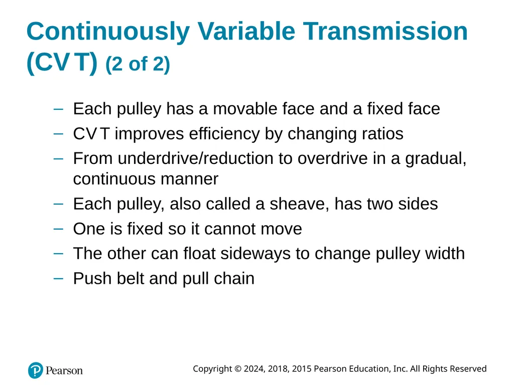
Continuously Variable Transmission (C V T) (2 of 2) Each pulley has a movable face and a fixed face
C V T improves efficiency by changing ratios
From underdrive/reduction to overdrive in a gradual, continuous manner
Each pulley, also called a sheave, has two sides
One is fixed so it cannot move
The other can float sideways to change pulley width
Push belt and pull chain<br>
05
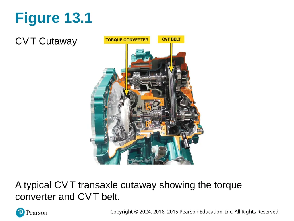
Figure 13.1 C V T Cutaway A typical C V T transaxle cutaway showing the torque converter and C V T belt.<br>
06
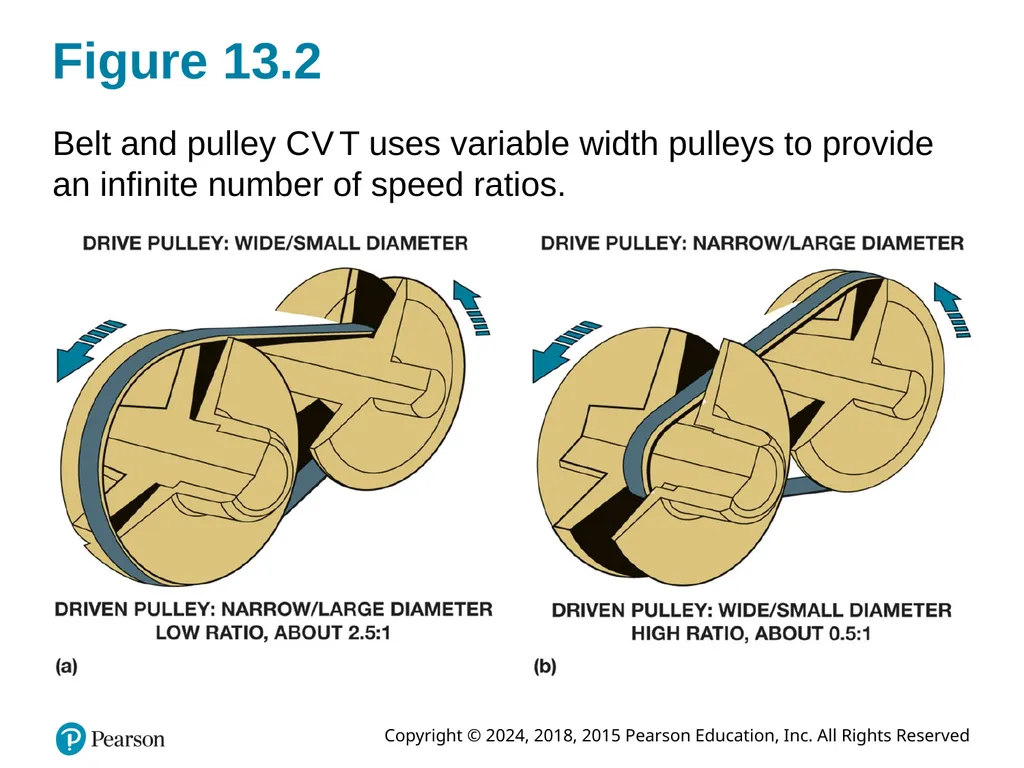
Figure 13.2 Belt and pulley C V T uses variable width pulleys to provide an infinite number of speed ratios.<br>
07
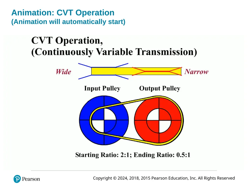
Animation: CVT Operation �(Animation will automatically start)<br>
08
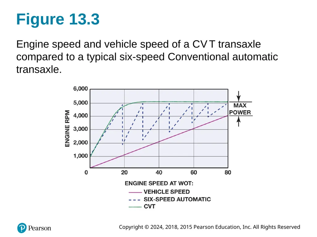
Figure 13.3 Engine speed and vehicle speed of a C V T transaxle compared to a typical six-speed Conventional automatic transaxle.<br>
09
Frequently Asked Question: What Is It Like to Drive a Vehicle Equipped with C V T? ? Frequently Asked Question What Is It Like to Drive a Vehicle Equipped with C V T? For most people, driving a vehicle equipped with a C V T is same as driving vehicle equipped with a conventional automatic transmission/transaxle. The vehicle creeps slightly when brake is released and accelerates normally when throttle is opened. Because no shifts occur, first thing driver and passenger notice is that it is very smooth. If vehicle is equipped with a tachometer, driver may notice that engine speed increases when first accelerating and often remains higher until vehicle speed increases. During periods of rapid acceleration, engine speed may be close to its maximum and thereby creates noise and vibration often not experienced in a similar vehicle. Because vehicle speed slowly catches up to engine speed, this effect is often referred to as “rubber band effect” and is most noticeable only during periods of rapid acceleration. However, the fuel economy improvement of a C V T compared to a conventional automatic transmission makes slight difference a reasonable trade-off.<br>
10
Construction Variators
Pulleys used in C V T design can vary their width
Varying hydraulic pressure applied to them.
Drive Belt
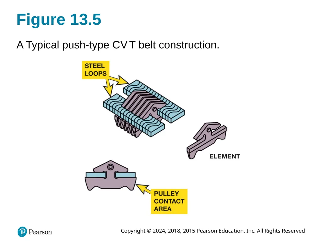
Push belt
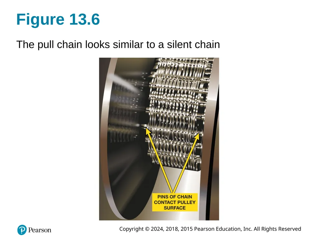
Pull chain<br>
11
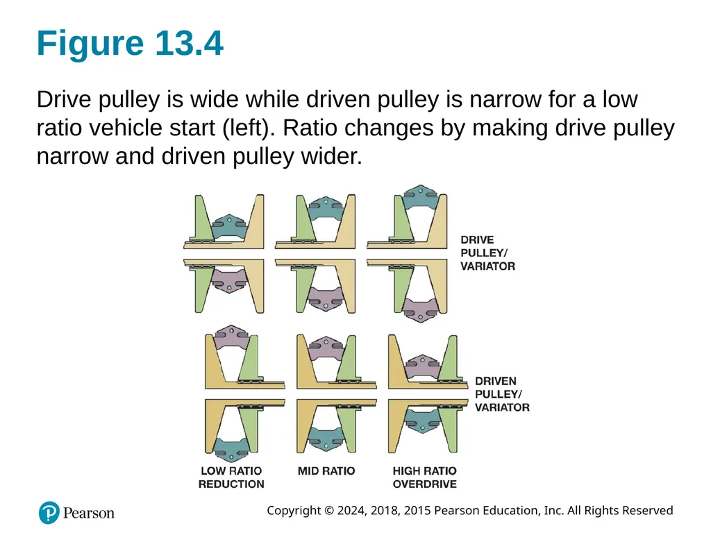
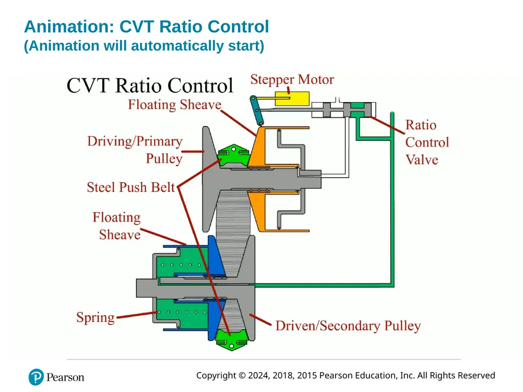
Figure 13.4 Drive pulley is wide while driven pulley is narrow for a low ratio vehicle start (left). Ratio changes by making drive pulley narrow and driven pulley wider.<br>
12
Animation: CVT Ratio Control�(Animation will automatically start)<br>
13
Figure 13.5 A Typical push-type C V T belt construction.<br>
14
Figure 13.6 The pull chain looks similar to a silent chain<br>
15
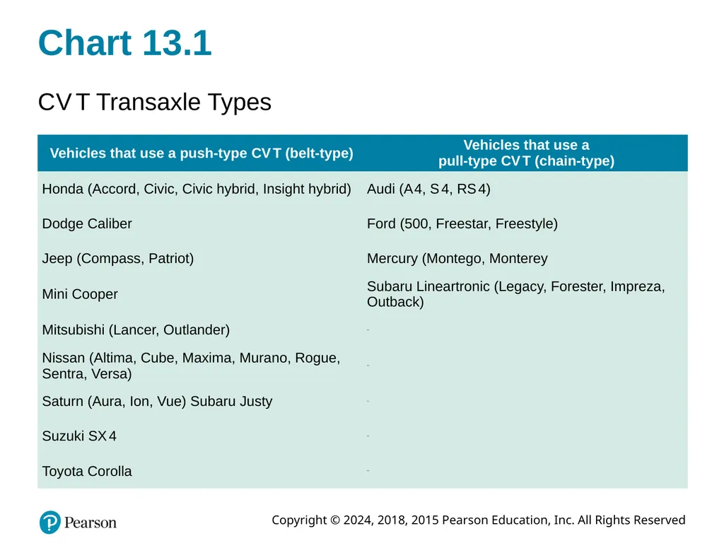
Chart 13.1 C V T Transaxle Types<br>
16
C V T Electronic Controls (1 of 3) Inputs: (Page 186-189)
Transmission Range Sensor
Input Speed Sensor
Output Speed Sensor
Primary Pressure Sensor
Secondary Pressure Sensor
Transmission Temperature Sensor<br>
17
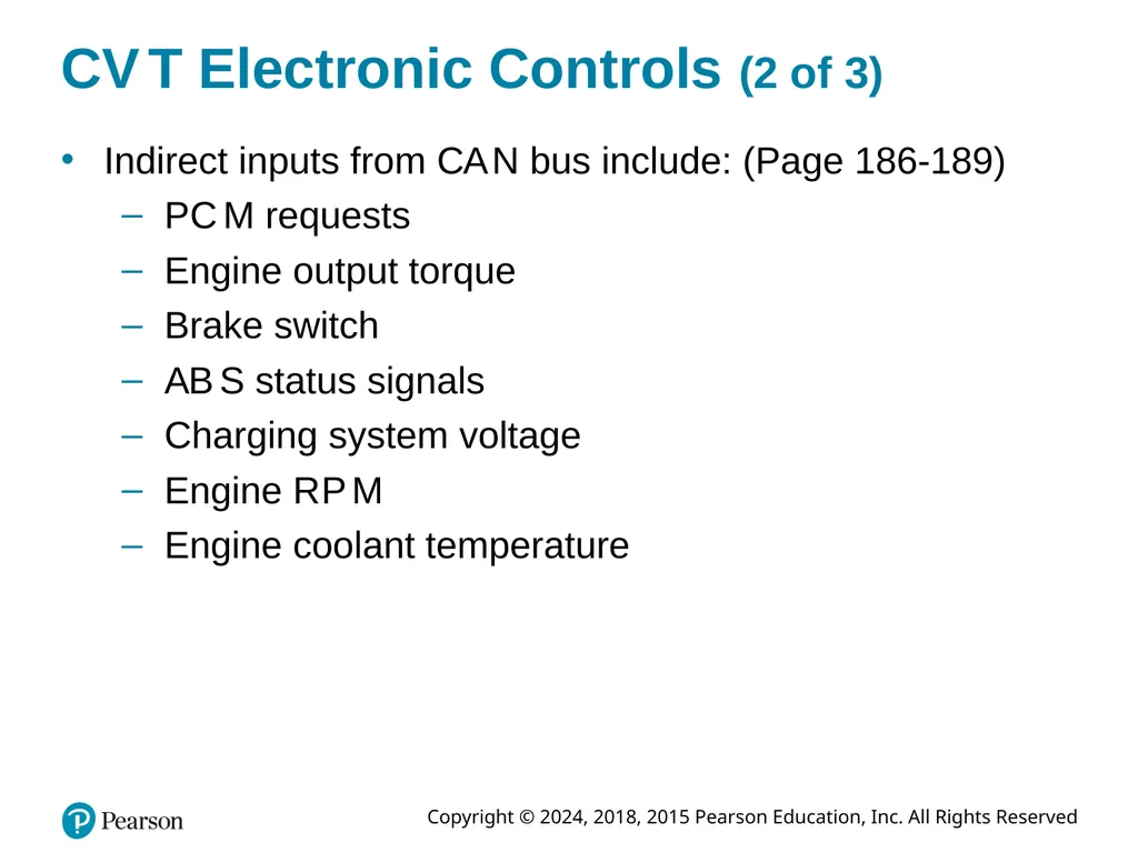
C V T Electronic Controls (2 of 3) Indirect inputs from C A N bus include: (Page 186-189)
P C M requests
Engine output torque
Brake switch
A B S status signals
Charging system voltage
Engine R P M
Engine coolant temperature<br>
18
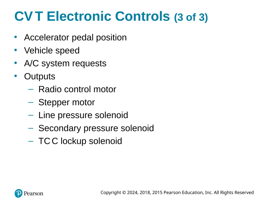
C V T Electronic Controls (3 of 3) Accelerator pedal position
Vehicle speed
A/C system requests
Outputs
Radio control motor
Stepper motor
Line pressure solenoid
Secondary pressure solenoid
T C C lockup solenoid<br>
19
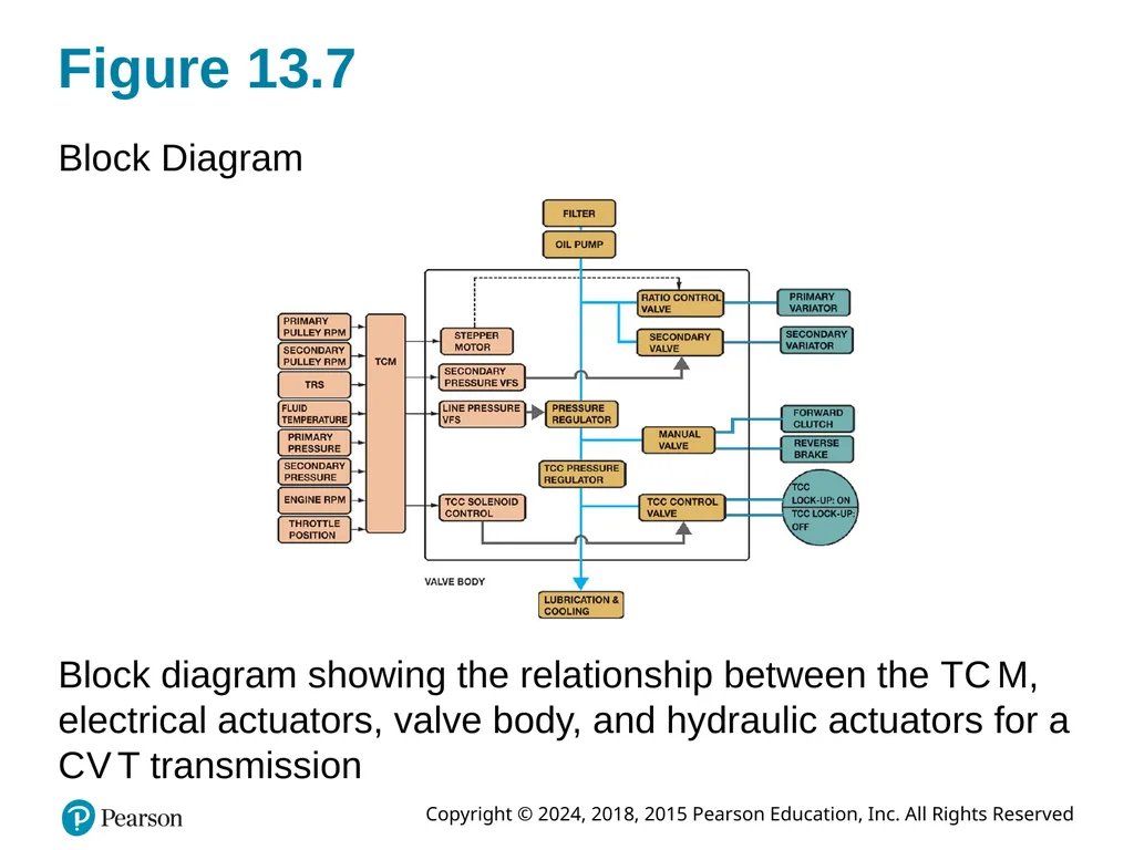
Figure 13.7 Block Diagram Block diagram showing the relationship between the T C M, electrical actuators, valve body, and hydraulic actuators for a C V T transmission<br>
20
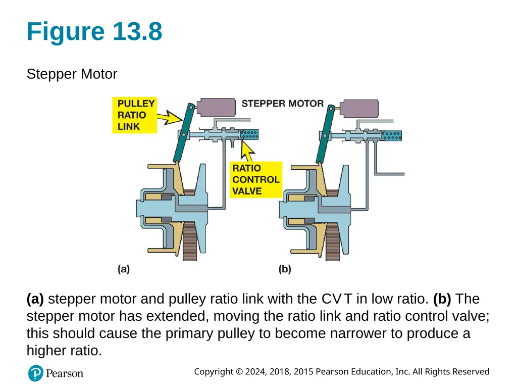
Figure 13.8 Stepper Motor (a) stepper motor and pulley ratio link with the C V T in low ratio. (b) The stepper motor has extended, moving the ratio link and ratio control valve; this should cause the primary pulley to become narrower to produce a higher ratio.<br>
21
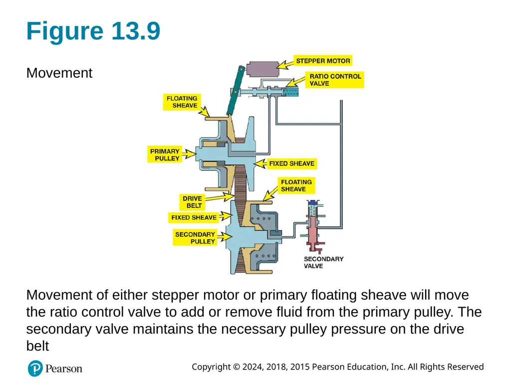
Figure 13.9 Movement Movement of either stepper motor or primary floating sheave will move the ratio control valve to add or remove fluid from the primary pulley. The secondary valve maintains the necessary pulley pressure on the drive belt<br>
22
C V T Operation Describe what happens during Starting
Reverse
Forward<br>
23
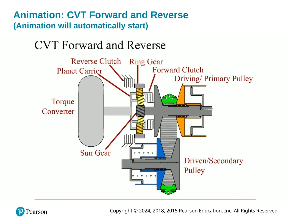
Animation: CVT Forward and Reverse�(Animation will automatically start)<br>
24
C V T Torque Converter Most C V T transmissions use a low-profile elliptical torque converter with a lockup clutch
Since C V T S are infinitely variable torque converter not needed once the vehicle is moving.<br>
25
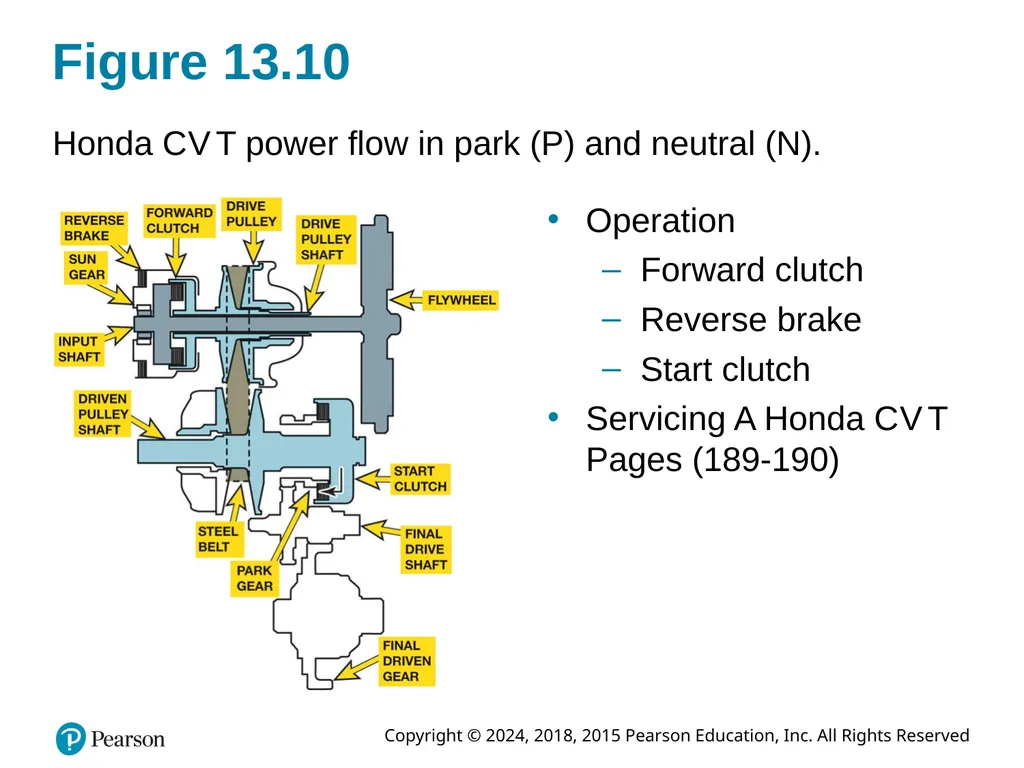
Figure 13.10 Honda C V T power flow in park (P) and neutral (N). Operation
Forward clutch
Reverse brake
Start clutch
Servicing A Honda C V T Pages (189-190)<br>
26
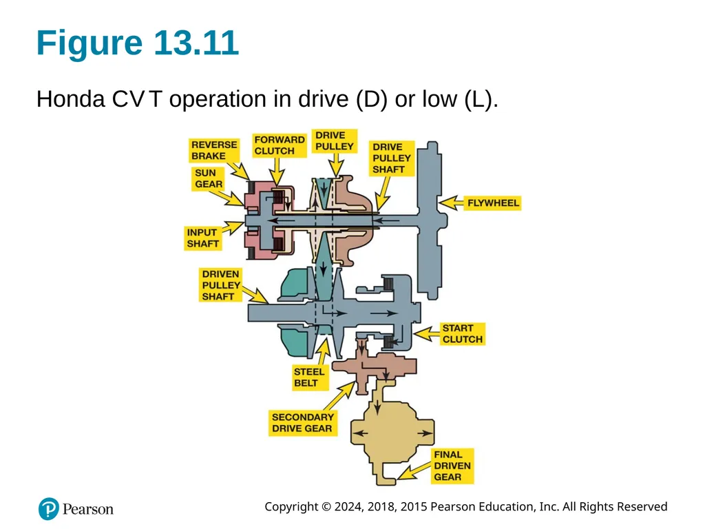
Figure 13.11 Honda C V T operation in drive (D) or low (L).<br>
27
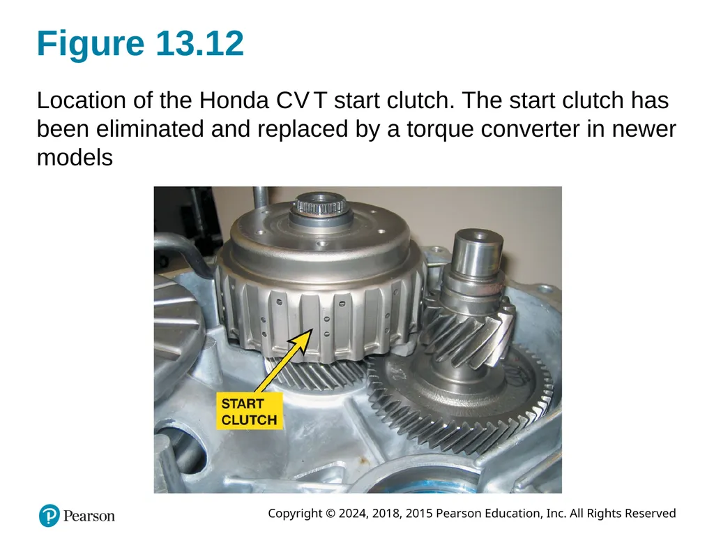
Figure 13.12 Location of the Honda C V T start clutch. The start clutch has been eliminated and replaced by a torque converter in newer models<br>
28
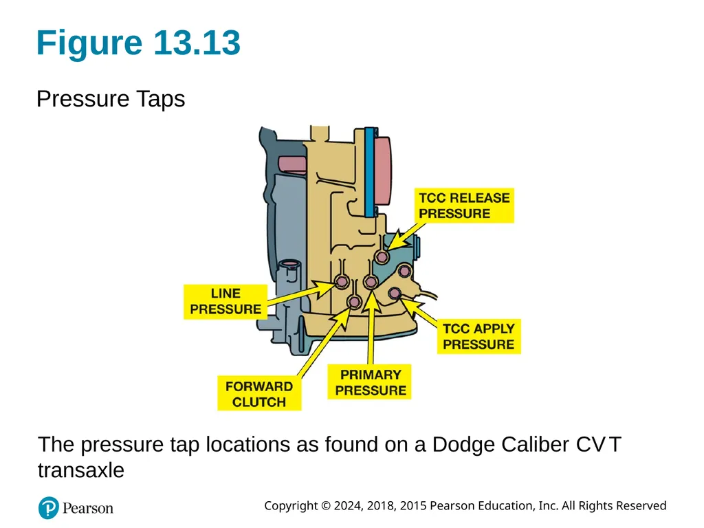
Pressure Testing C V T Pressure Testing
Typical pressures:
Mainline pressure 70 to 900 P S I (485 to 6,200 k P a)
Primary pressure 15 to 900 P S I (100 to 6,200 k P a)
Secondary pressure 15 to 900 P S I (100 to 6,200 k P a)<br>
29
Figure 13.13 Pressure Taps The pressure tap locations as found on a Dodge Caliber C V T transaxle<br>
30
C V T Fluid Checking C V T fluid level
Replacing C V T Fluid
C V T Fluid Options
Option 1
Option 2<br>
31
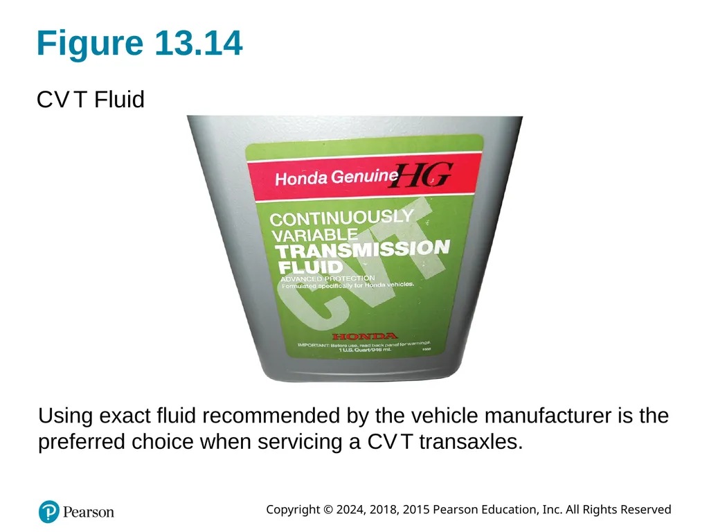
Figure 13.14 C V T Fluid Using exact fluid recommended by the vehicle manufacturer is the preferred choice when servicing a C V T transaxles.<br>
32
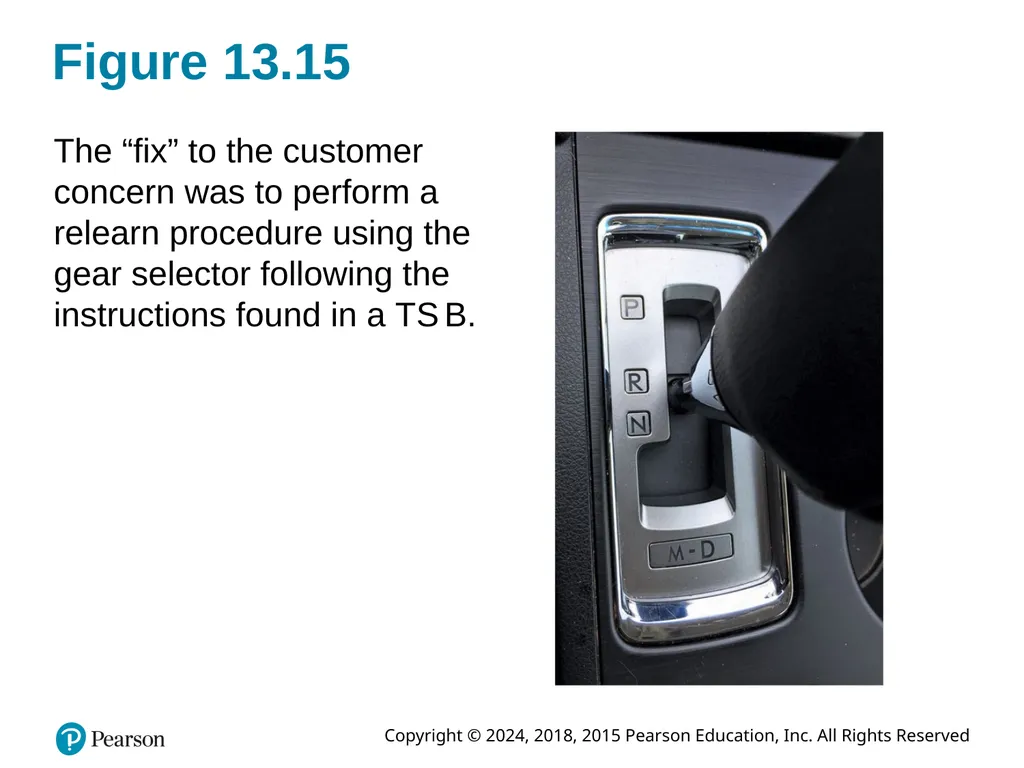
Figure 13.15 The “fix” to the customer concern was to perform a relearn procedure using the gear selector following the instructions found in a T S B.<br>
33
C V T Noise Issues Describe what the following sounds mean (Pages 191-192)
“Growl”
“Whine”
“Ticking”<br>
34
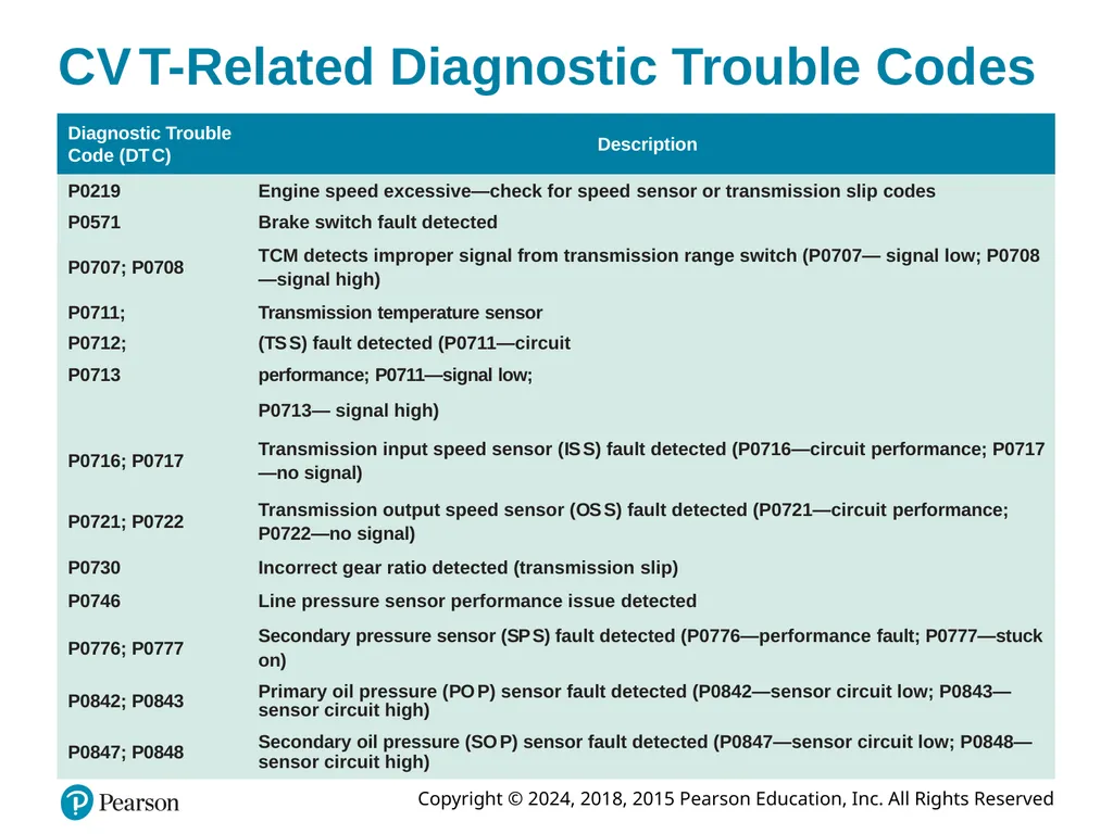
C V T-Related Diagnostic Trouble Codes<br>
35
Question 1 How is a variable ratio achieved in a C V T? A. By using multiple gears
B. By using a steel belt with two variable-width pulleys
C. By using a start clutch assembly
D. By using a variable-torque converter<br>
36
Answer 1 How is a variable ratio achieved in a C V T? B. By using a steel belt with two variable-width pulleys<br>
37
Summary (1 of 2) C V T varies gear ratio in a continuous manner instead of in a series of steps or fixed gear ratios.
A pair of hydraulically controlled variable-size pulleys is used with a steel-link drive belt or chain.
Two styles of fixed-length steel belts are used
Push belt or a pull chain is used<br>
38
Summary (2 of 2) T C M of a C V T uses direct and indirect inputs
Monitor transmission and engine operation
Stepper motor is a linear position motor.
Changes position of the upper end of the pulley ratio link
Measuring oil pressure is similar to pressure testing
Conventional automatic transmissions/transaxles<br>
39
Automatic Transmissions and Transaxles Videos and Animations Videos Link: (A2) Automatic Transmissions and Transaxles Videos Animations Link: (A2) Automatic Transmissions and Transaxles Animations<br>
40
Copyright This work is protected by United States copyright laws and is provided solely for the use of instructors in teaching their courses and assessing student learning. Dissemination or sale of any part of this work (including on the World Wide Web) will destroy the integrity of the work and is not permitted. The work and materials from it should never be made available to students except by instructors using the accompanying text in their classes. All recipients of this work are expected to abide by these restrictions and to honor the intended pedagogical purposes and the needs of other instructors who rely on these materials.<br>