
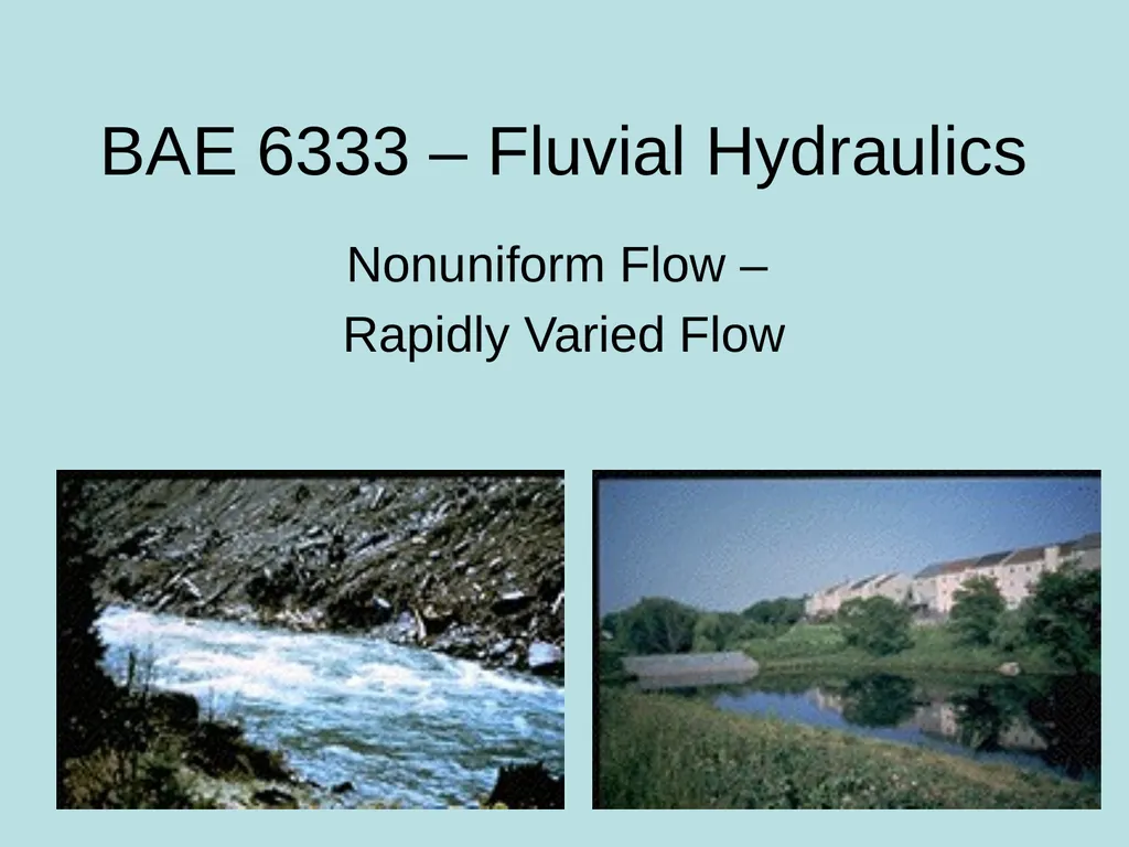
BAE 6333 – Fluvial Hydraulics Nonuniform Flow –

Description: BAE 6333 Fluvial Hydraulics Nonuniform Flow Rapidly Varied Flow Thus farAnd now beyond Ability to predict flow profile for gradually varied flow up to hc Rapidly Varied Flow downstream of critical depth over a short stream length
Related Topics
Download Presentation
"BAE 6333 – Fluvial Hydraulics Nonuniform Flow –" is the property of its rightful owner. Permission is granted to download and print the materials on this website for personal, non-commercial use only, and to display it on your personal computer provided you do not modify the materials and that you retain all copyright notices contained in the materials. By downloading content from our website, you accept the terms of this agreement.
Presentation Transcript
slide1. BAE 6333 – Fluvial Hydraulics Nonuniform Flow –
Rapidly Varied Flow<br>
slide2. Thus far…And now beyond Ability to predict flow profile for gradually varied flow – up to hc
Rapidly Varied Flow – downstream of critical depth over a short stream length
Supercritical to Subcritical
Subcritical to Supercritical
Implicit assumption from before of a hydrostatic pressure distribution is no longer valid<br>
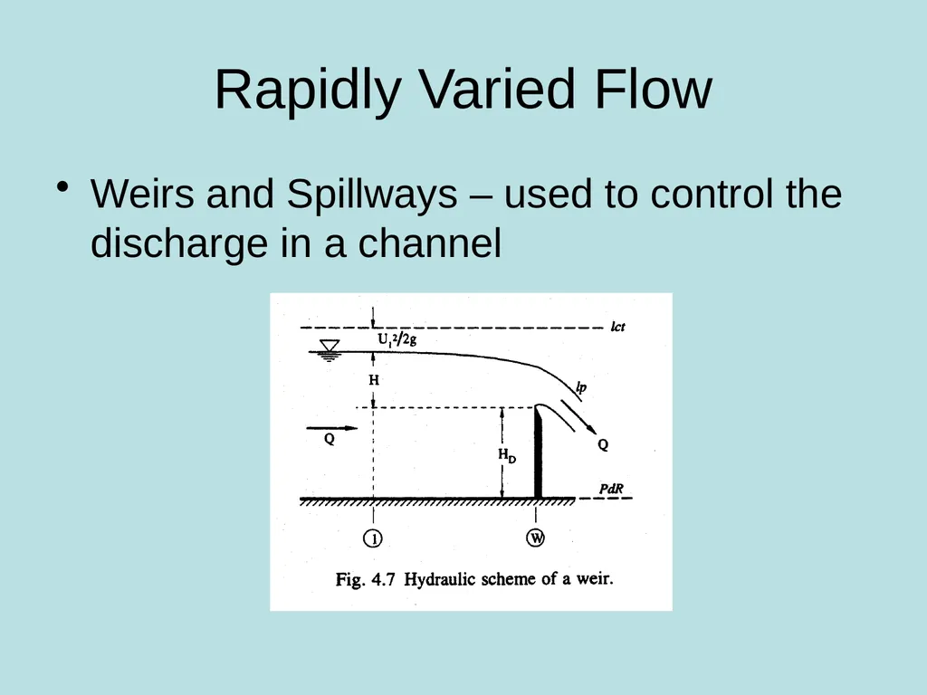
slide3. Rapidly Varied Flow Weirs and Spillways – used to control the discharge in a channel<br>
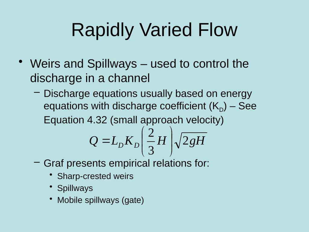
slide4. Rapidly Varied Flow Weirs and Spillways – used to control the discharge in a channel
Discharge equations usually based on energy equations with discharge coefficient (KD) – See Equation 4.32 (small approach velocity)
Graf presents empirical relations for:
Sharp-crested weirs
Spillways
Mobile spillways (gate)<br>
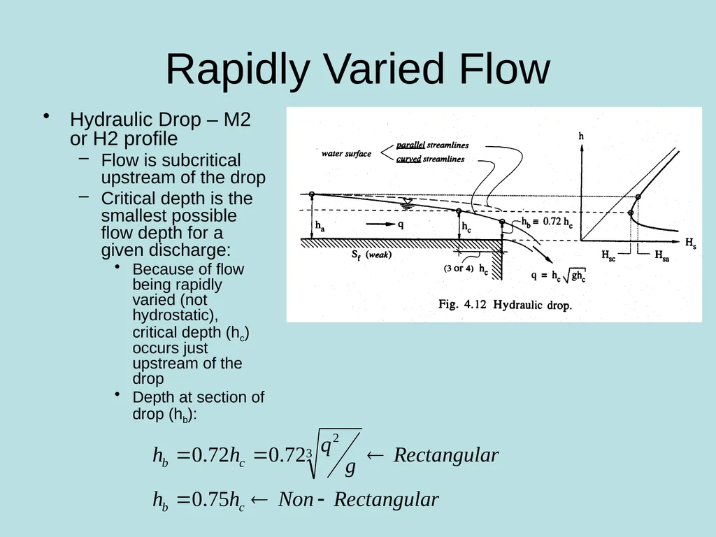
slide5. Rapidly Varied Flow Hydraulic Drop – M2 or H2 profile
Flow is subcritical upstream of the drop
Critical depth is the smallest possible flow depth for a given discharge:
Because of flow being rapidly varied (not hydrostatic), critical depth (hc) occurs just upstream of the drop
Depth at section of drop (hb):<br>
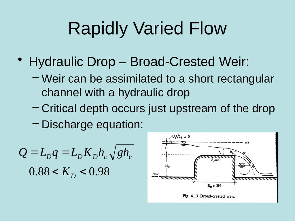
slide6. Rapidly Varied Flow Hydraulic Drop – Broad-Crested Weir:
Weir can be assimilated to a short rectangular channel with a hydraulic drop
Critical depth occurs just upstream of the drop
Discharge equation:<br>
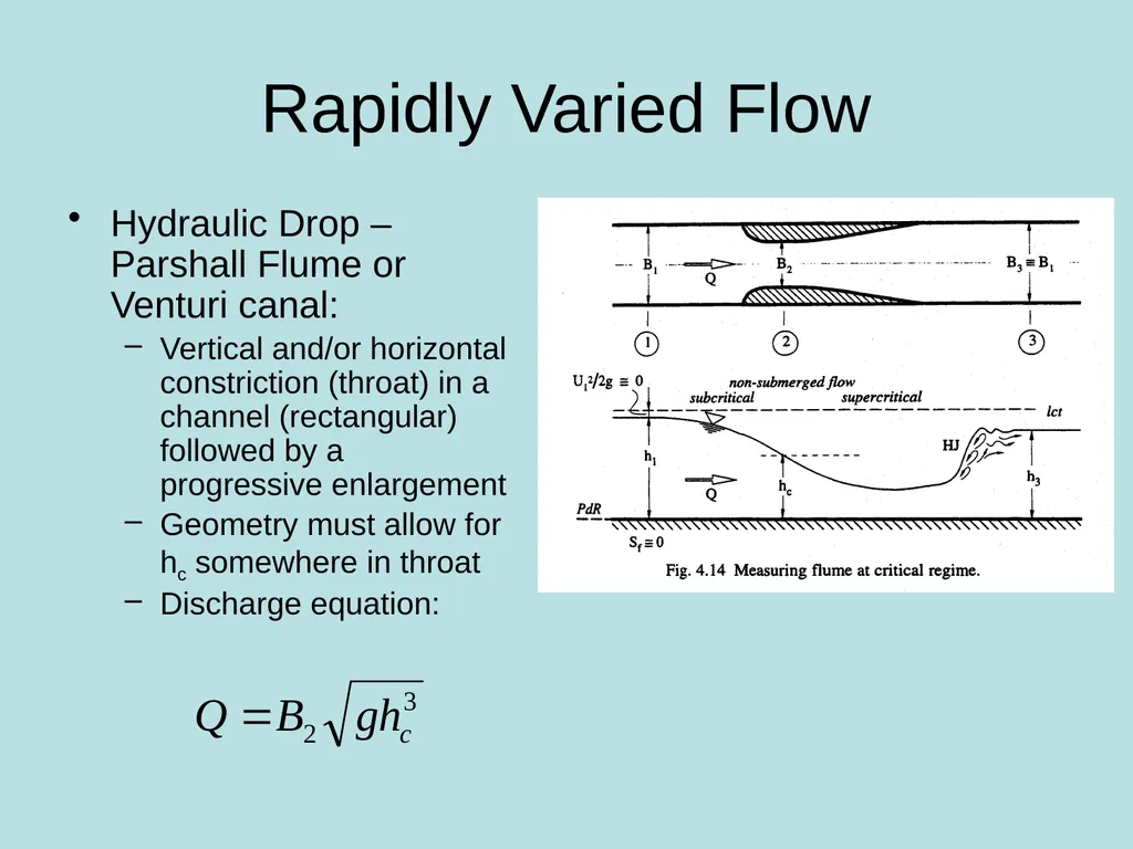
slide7. Rapidly Varied Flow Hydraulic Drop – Parshall Flume or Venturi canal:
Vertical and/or horizontal constriction (throat) in a channel (rectangular) followed by a progressive enlargement
Geometry must allow for hc somewhere in throat
Discharge equation:<br>
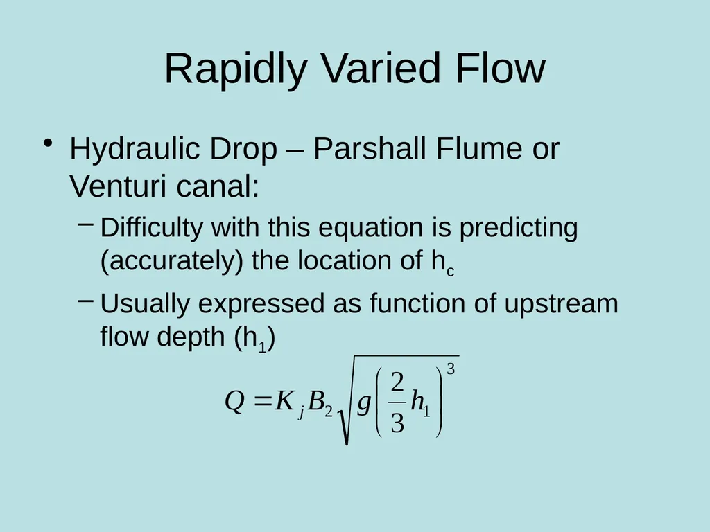
slide8. Rapidly Varied Flow Hydraulic Drop – Parshall Flume or Venturi canal:
Difficulty with this equation is predicting (accurately) the location of hc
Usually expressed as function of upstream flow depth (h1)<br>
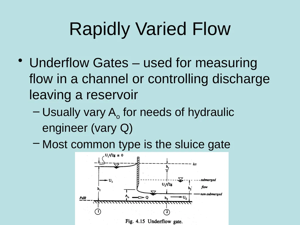
slide9. Rapidly Varied Flow Underflow Gates – used for measuring flow in a channel or controlling discharge leaving a reservoir
Usually vary Ao for needs of hydraulic engineer (vary Q)
Most common type is the sluice gate<br>
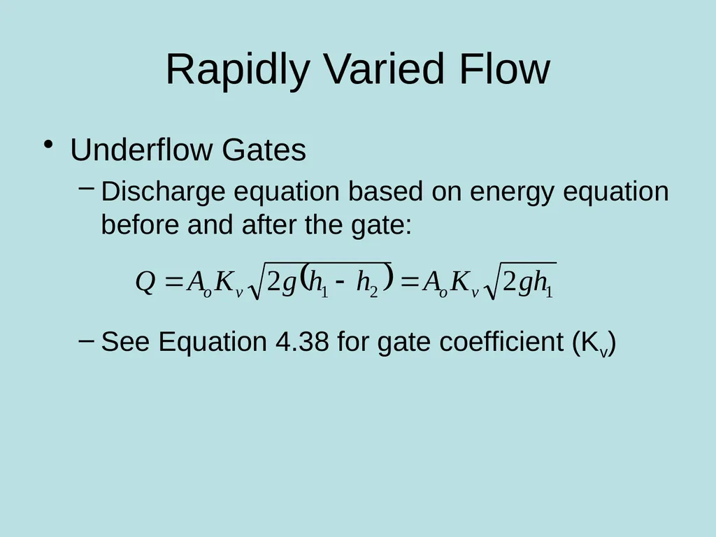
slide10. Rapidly Varied Flow Underflow Gates
Discharge equation based on energy equation before and after the gate:
See Equation 4.38 for gate coefficient (Kv)<br>
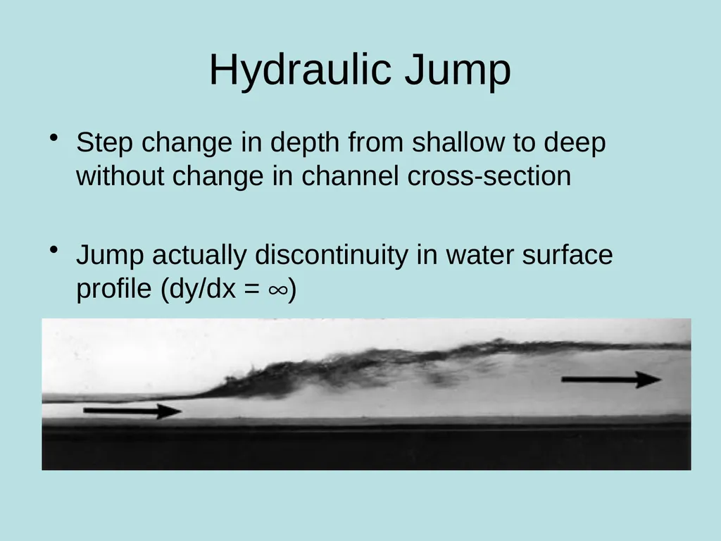
slide11. Hydraulic Jump Step change in depth from shallow to deep without change in channel cross-section
Jump actually discontinuity in water surface profile (dy/dx = ¥)<br>
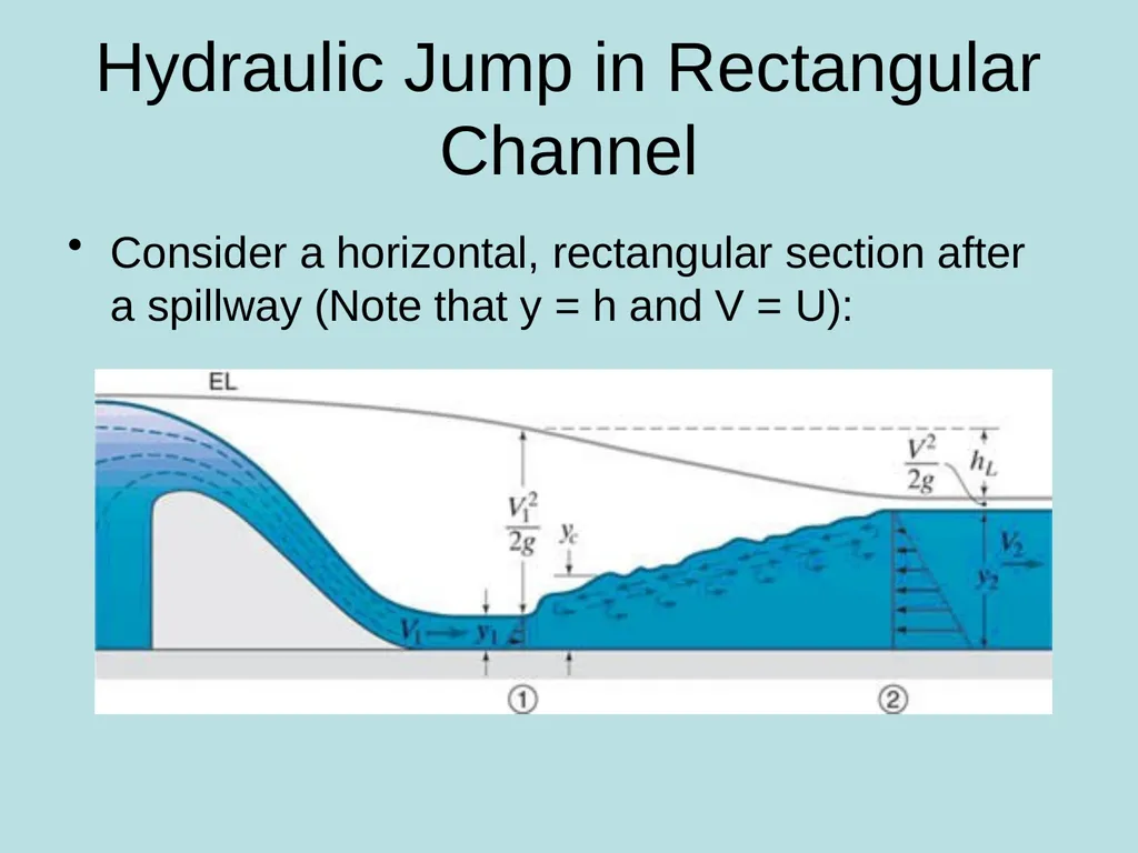
slide12. Hydraulic Jump in Rectangular Channel Consider a horizontal, rectangular section after a spillway (Note that y = h and V = U):<br>
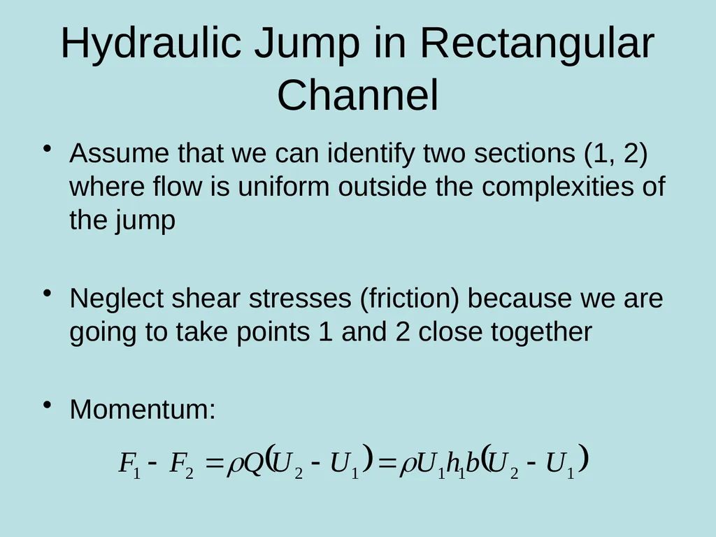
slide13. Hydraulic Jump in Rectangular Channel Assume that we can identify two sections (1, 2) where flow is uniform outside the complexities of the jump
Neglect shear stresses (friction) because we are going to take points 1 and 2 close together
Momentum:<br>
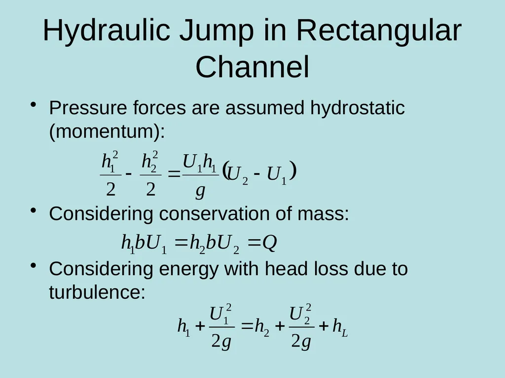
slide14. Pressure forces are assumed hydrostatic (momentum):
Considering conservation of mass:
Considering energy with head loss due to turbulence: Hydraulic Jump in Rectangular Channel<br>
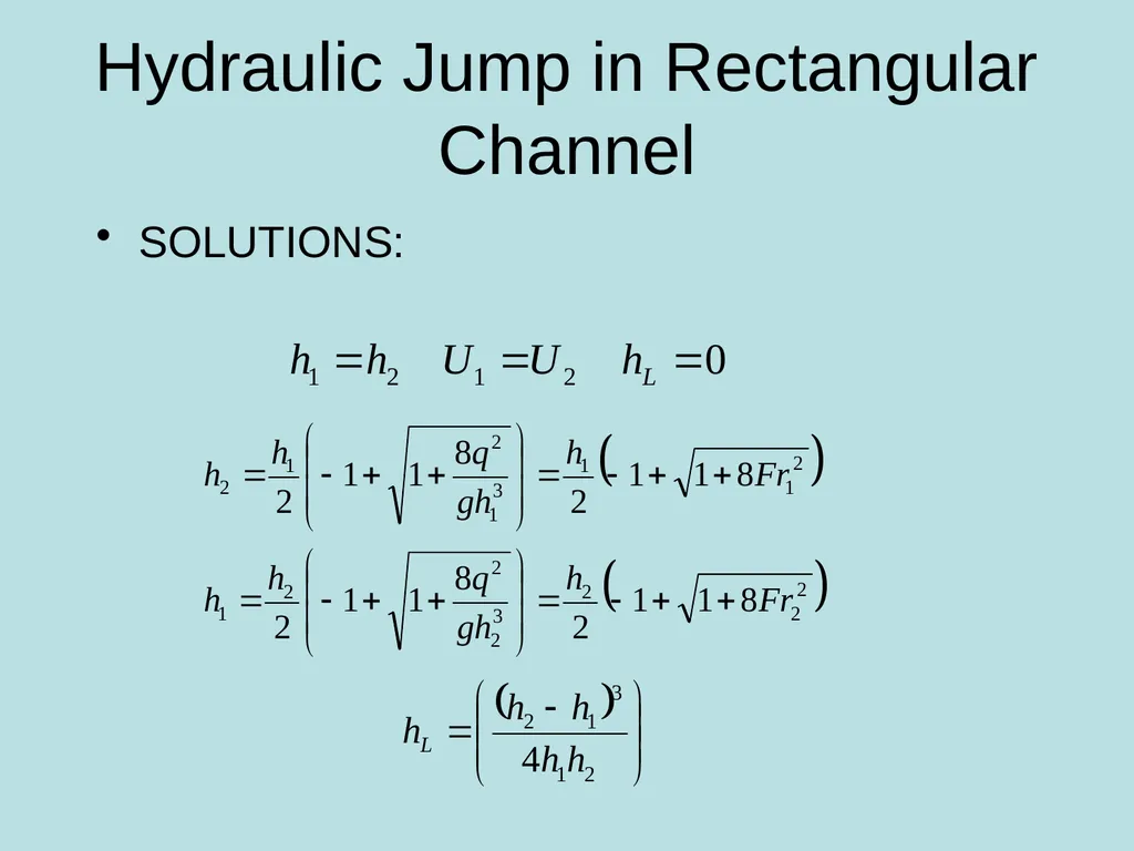
slide15. SOLUTIONS: Hydraulic Jump in Rectangular Channel<br>
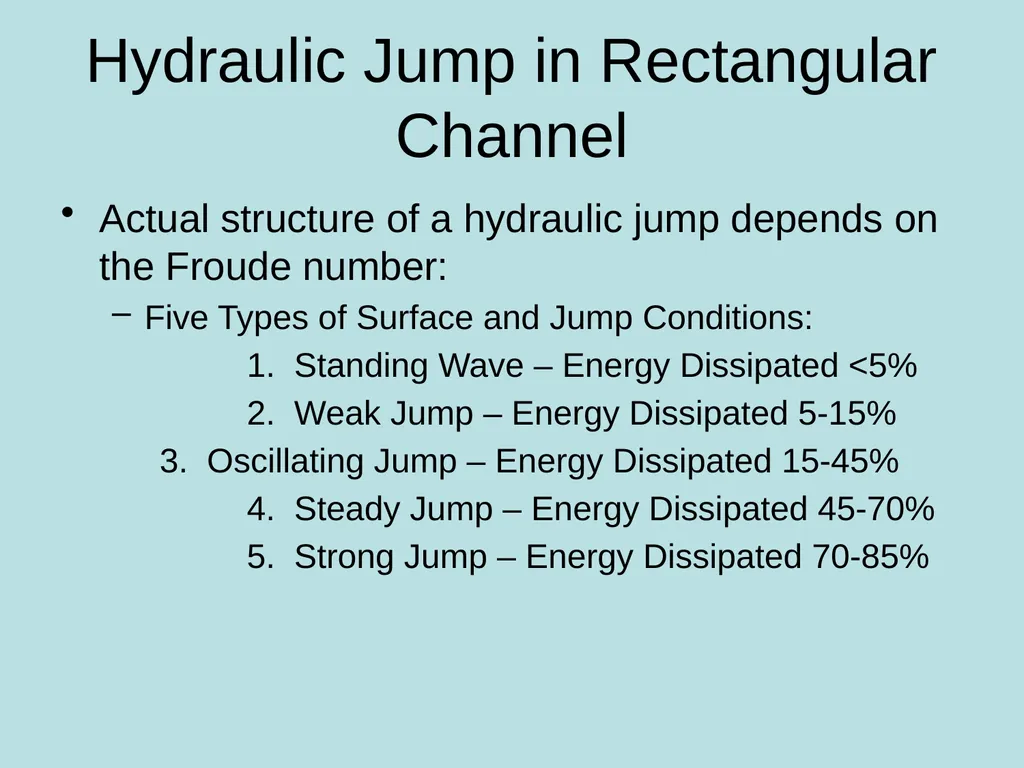
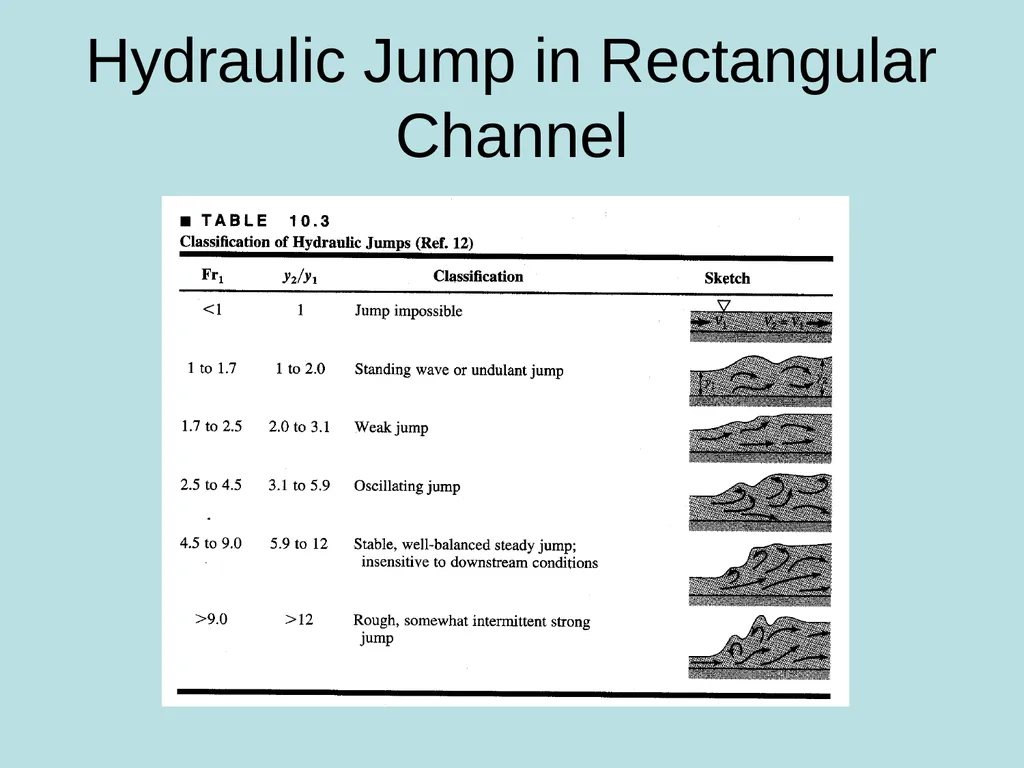
slide16. Actual structure of a hydraulic jump depends on the Froude number:
Five Types of Surface and Jump Conditions:
1. Standing Wave – Energy Dissipated <5%
2. Weak Jump – Energy Dissipated 5-15%
3. Oscillating Jump – Energy Dissipated 15-45%
4. Steady Jump – Energy Dissipated 45-70%
5. Strong Jump – Energy Dissipated 70-85% Hydraulic Jump in Rectangular Channel<br>
slide17. Hydraulic Jump in Rectangular Channel<br>
Rapidly Varied Flow<br>
slide2. Thus far…And now beyond Ability to predict flow profile for gradually varied flow – up to hc
Rapidly Varied Flow – downstream of critical depth over a short stream length
Supercritical to Subcritical
Subcritical to Supercritical
Implicit assumption from before of a hydrostatic pressure distribution is no longer valid<br>
slide3. Rapidly Varied Flow Weirs and Spillways – used to control the discharge in a channel<br>
slide4. Rapidly Varied Flow Weirs and Spillways – used to control the discharge in a channel
Discharge equations usually based on energy equations with discharge coefficient (KD) – See Equation 4.32 (small approach velocity)
Graf presents empirical relations for:
Sharp-crested weirs
Spillways
Mobile spillways (gate)<br>
slide5. Rapidly Varied Flow Hydraulic Drop – M2 or H2 profile
Flow is subcritical upstream of the drop
Critical depth is the smallest possible flow depth for a given discharge:
Because of flow being rapidly varied (not hydrostatic), critical depth (hc) occurs just upstream of the drop
Depth at section of drop (hb):<br>
slide6. Rapidly Varied Flow Hydraulic Drop – Broad-Crested Weir:
Weir can be assimilated to a short rectangular channel with a hydraulic drop
Critical depth occurs just upstream of the drop
Discharge equation:<br>
slide7. Rapidly Varied Flow Hydraulic Drop – Parshall Flume or Venturi canal:
Vertical and/or horizontal constriction (throat) in a channel (rectangular) followed by a progressive enlargement
Geometry must allow for hc somewhere in throat
Discharge equation:<br>
slide8. Rapidly Varied Flow Hydraulic Drop – Parshall Flume or Venturi canal:
Difficulty with this equation is predicting (accurately) the location of hc
Usually expressed as function of upstream flow depth (h1)<br>
slide9. Rapidly Varied Flow Underflow Gates – used for measuring flow in a channel or controlling discharge leaving a reservoir
Usually vary Ao for needs of hydraulic engineer (vary Q)
Most common type is the sluice gate<br>
slide10. Rapidly Varied Flow Underflow Gates
Discharge equation based on energy equation before and after the gate:
See Equation 4.38 for gate coefficient (Kv)<br>
slide11. Hydraulic Jump Step change in depth from shallow to deep without change in channel cross-section
Jump actually discontinuity in water surface profile (dy/dx = ¥)<br>
slide12. Hydraulic Jump in Rectangular Channel Consider a horizontal, rectangular section after a spillway (Note that y = h and V = U):<br>
slide13. Hydraulic Jump in Rectangular Channel Assume that we can identify two sections (1, 2) where flow is uniform outside the complexities of the jump
Neglect shear stresses (friction) because we are going to take points 1 and 2 close together
Momentum:<br>
slide14. Pressure forces are assumed hydrostatic (momentum):
Considering conservation of mass:
Considering energy with head loss due to turbulence: Hydraulic Jump in Rectangular Channel<br>
slide15. SOLUTIONS: Hydraulic Jump in Rectangular Channel<br>
slide16. Actual structure of a hydraulic jump depends on the Froude number:
Five Types of Surface and Jump Conditions:
1. Standing Wave – Energy Dissipated <5%
2. Weak Jump – Energy Dissipated 5-15%
3. Oscillating Jump – Energy Dissipated 15-45%
4. Steady Jump – Energy Dissipated 45-70%
5. Strong Jump – Energy Dissipated 70-85% Hydraulic Jump in Rectangular Channel<br>
slide17. Hydraulic Jump in Rectangular Channel<br>