
Boolean Algebra Chapter 12 With Question/Answer
AM
Published · 28 slides · 0 views
1 / 1



Description
Boolean Algebra Chapter 12 With QuestionAnswer Animations McGraw Hill LLC. All rights reserved. No reproduction or distribution without the prior written consent of McGraw Hill LLC. Chapter Summary Boolean Functions. Representing Boolean
Related Topics
Share
Embed code
Download this presentation From Below
"Boolean Algebra Chapter 12 With Question/Answer" is the property of its rightful owner. Permission is granted to download and print the materials on this website for personal, non-commercial use only, and to display it on your personal computer provided you do not modify the materials and that you retain all copyright notices contained in the materials. By downloading content from our website, you accept the terms of this agreement.
Presentation Transcript
01
Boolean Algebra Chapter 12 With Question/Answer Animations © McGraw Hill LLC. All rights reserved. No reproduction or distribution without the prior written consent of McGraw Hill LLC.<br>
02
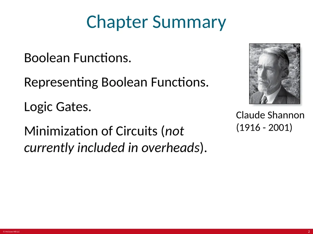
Chapter Summary Boolean Functions.
Representing Boolean Functions.
Logic Gates.
Minimization of Circuits (not currently included in overheads). Claude Shannon (1916 - 2001) 2<br>
Representing Boolean Functions.
Logic Gates.
Minimization of Circuits (not currently included in overheads). Claude Shannon (1916 - 2001) 2<br>
03
Boolean Functions Section 12.1 3<br>
04
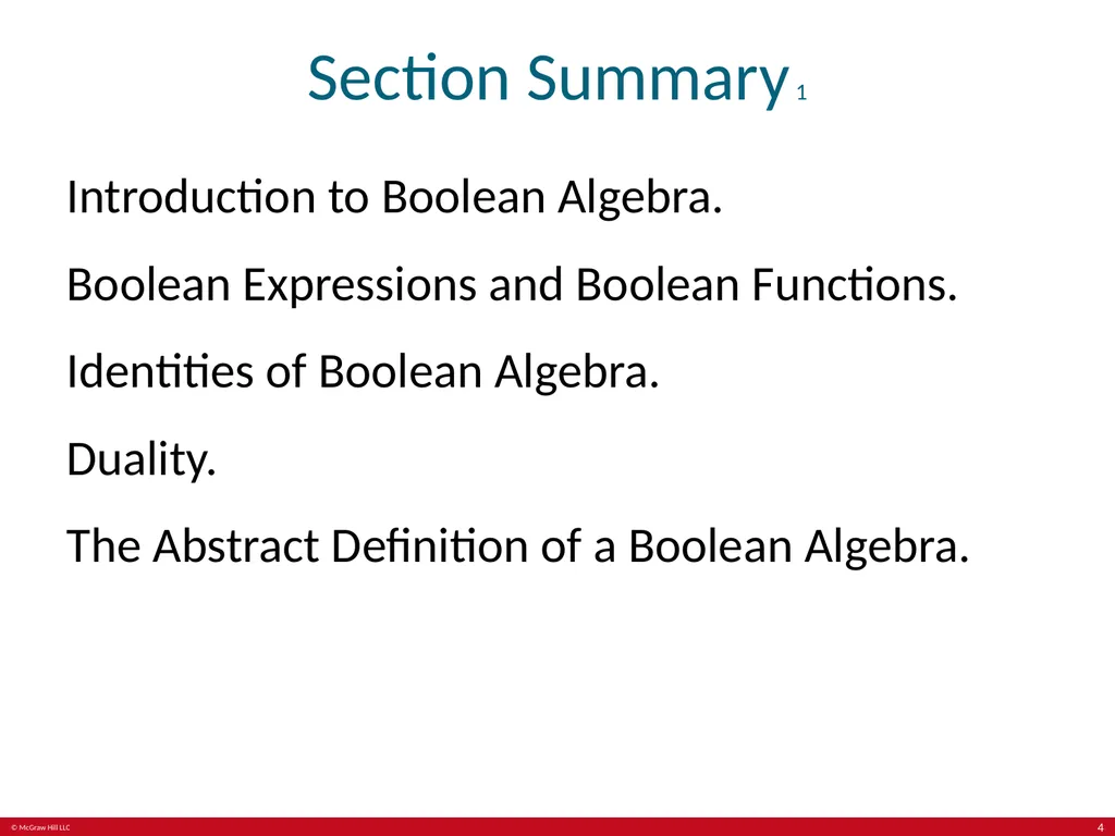
Section Summary 1 Introduction to Boolean Algebra.
Boolean Expressions and Boolean Functions.
Identities of Boolean Algebra.
Duality.
The Abstract Definition of a Boolean Algebra. 4<br>
Boolean Expressions and Boolean Functions.
Identities of Boolean Algebra.
Duality.
The Abstract Definition of a Boolean Algebra. 4<br>
05
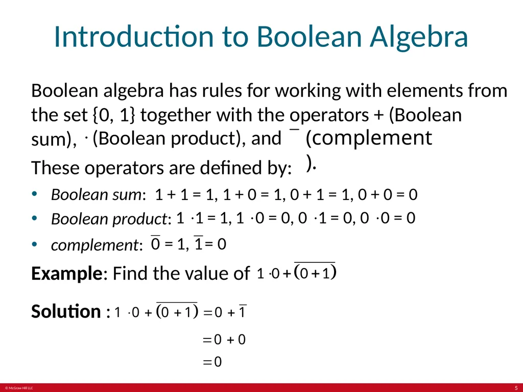
Introduction to Boolean Algebra Boolean algebra has rules for working with elements from the set {0, 1} together with the operators + (Boolean sum), (Boolean product), and (complement). These operators are defined by:
Boolean sum: 1 + 1 = 1, 1 + 0 = 1, 0 + 1 = 1, 0 + 0 = 0 Boolean product: complement: Example: Find the value of Solution : 5<br>
Boolean sum: 1 + 1 = 1, 1 + 0 = 1, 0 + 1 = 1, 0 + 0 = 0 Boolean product: complement: Example: Find the value of Solution : 5<br>
06
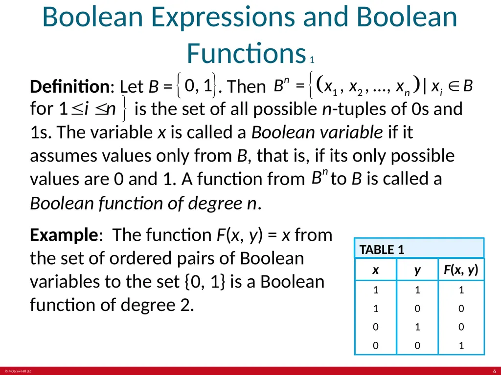
Boolean Expressions and Boolean Functions 1 Definition: Let B = . Then is the set of all possible n-tuples of 0s and 1s. The variable x is called a Boolean variable if it assumes values only from B, that is, if its only possible values are 0 and 1. A function from to B is called a Boolean function of degree n.
Example: The function F(x, y) = x from the set of ordered pairs of Boolean variables to the set {0, 1} is a Boolean function of degree 2. TABLE 1 6<br>
Example: The function F(x, y) = x from the set of ordered pairs of Boolean variables to the set {0, 1} is a Boolean function of degree 2. TABLE 1 6<br>
07
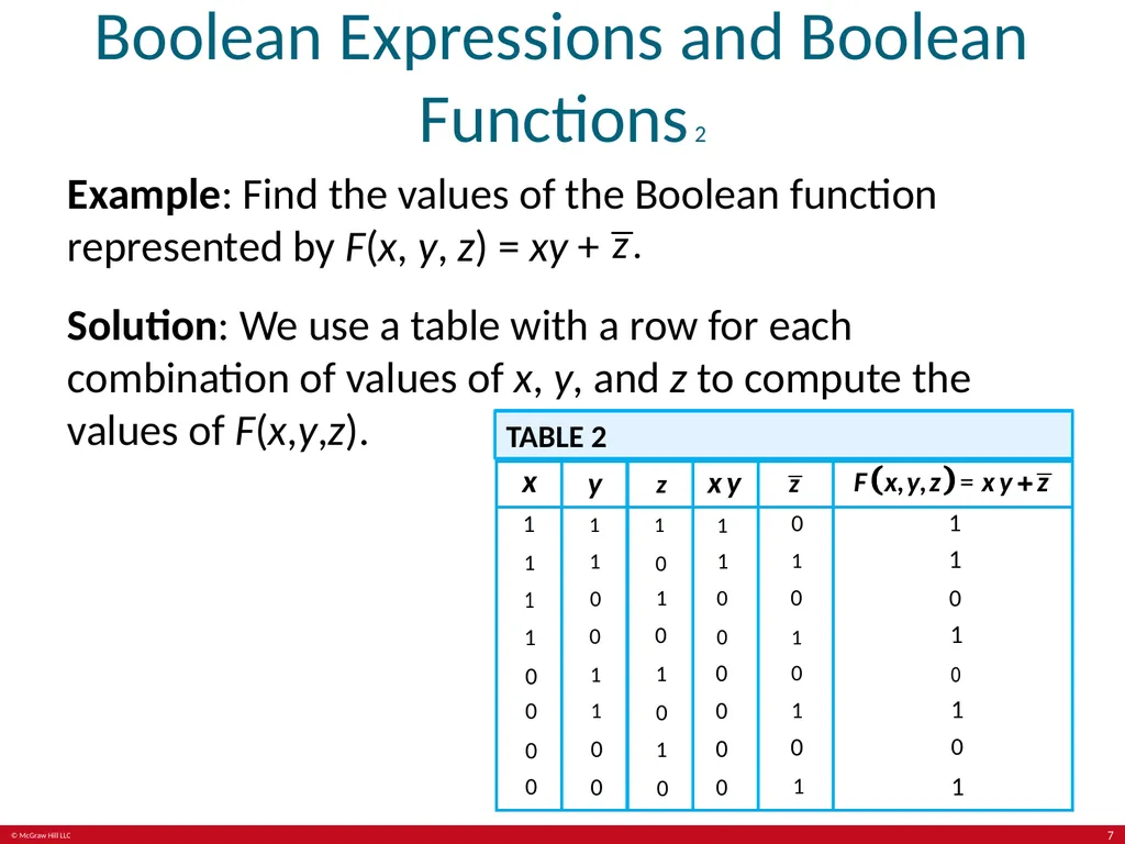
Boolean Expressions and Boolean Functions 2 Example: Find the values of the Boolean function represented by F(x, y, z) = xy + Solution: We use a table with a row for each combination of values of x, y, and z to compute the values of F(x,y,z). TABLE 2 7<br>
08
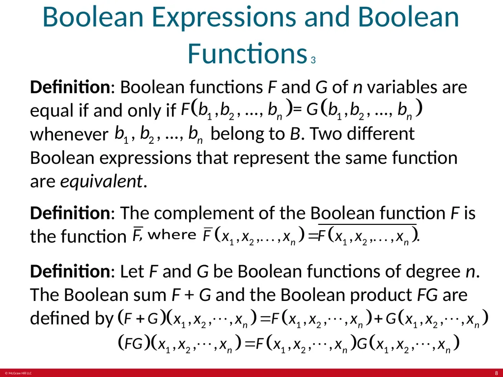
Boolean Expressions and Boolean Functions 3 Definition: Boolean functions F and G of n variables are equal if and only if whenever belong to B. Two different Boolean expressions that represent the same function are equivalent.
Definition: The complement of the Boolean function F is the function Definition: Let F and G be Boolean functions of degree n. The Boolean sum F + G and the Boolean product FG are defined by 8<br>
Definition: The complement of the Boolean function F is the function Definition: Let F and G be Boolean functions of degree n. The Boolean sum F + G and the Boolean product FG are defined by 8<br>
09
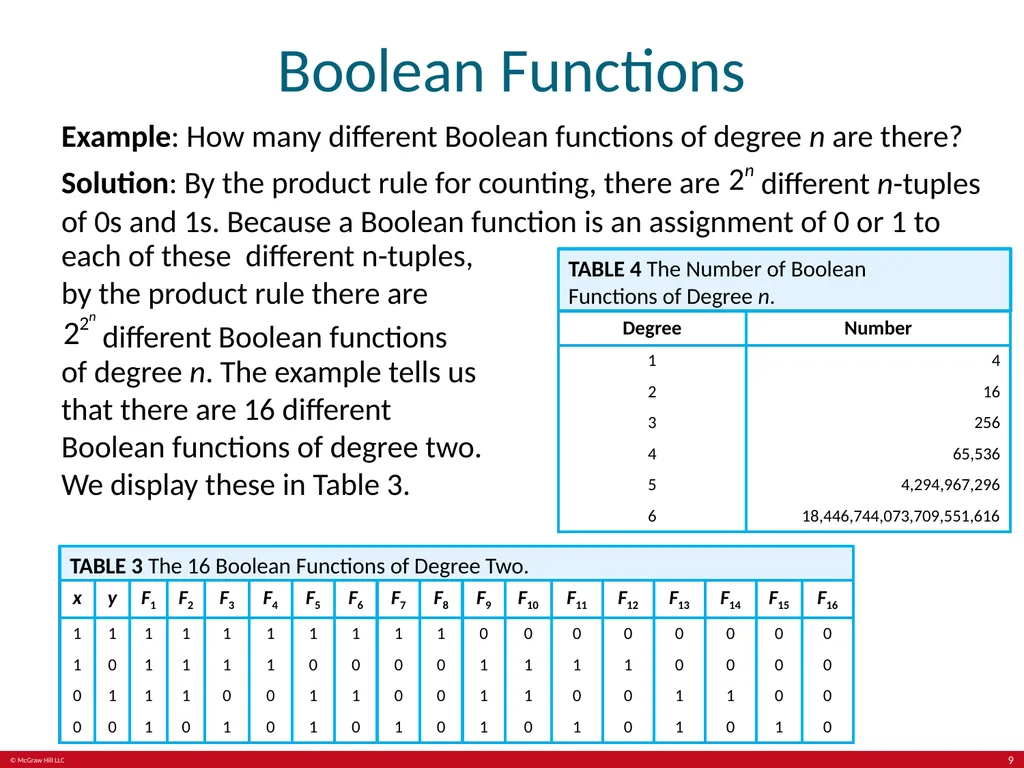
Boolean Functions Example: How many different Boolean functions of degree n are there?
Solution: By the product rule for counting, there are different n-tuples of 0s and 1s. Because a Boolean function is an assignment of 0 or 1 to each of these different n-tuples, by the product rule there are different Boolean functions of degree n. The example tells us that there are 16 different Boolean functions of degree two. We display these in Table 3. TABLE 3 The 16 Boolean Functions of Degree Two. TABLE 4 The Number of Boolean Functions of Degree n. 9<br>
Solution: By the product rule for counting, there are different n-tuples of 0s and 1s. Because a Boolean function is an assignment of 0 or 1 to each of these different n-tuples, by the product rule there are different Boolean functions of degree n. The example tells us that there are 16 different Boolean functions of degree two. We display these in Table 3. TABLE 3 The 16 Boolean Functions of Degree Two. TABLE 4 The Number of Boolean Functions of Degree n. 9<br>
10
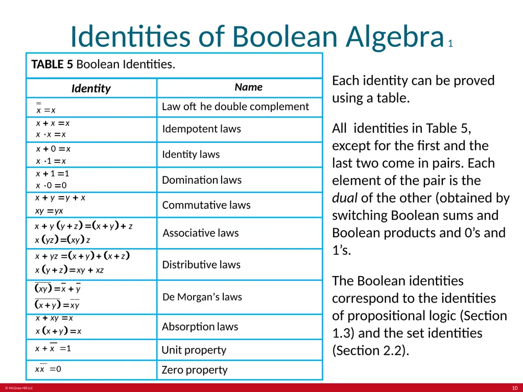
Identities of Boolean Algebra 1 TABLE 5 Boolean Identities. Each identity can be proved using a table.
All identities in Table 5, except for the first and the last two come in pairs. Each element of the pair is the dual of the other (obtained by switching Boolean sums and Boolean products and 0’s and 1’s.
The Boolean identities correspond to the identities of propositional logic (Section 1.3) and the set identities (Section 2.2). 10<br>
All identities in Table 5, except for the first and the last two come in pairs. Each element of the pair is the dual of the other (obtained by switching Boolean sums and Boolean products and 0’s and 1’s.
The Boolean identities correspond to the identities of propositional logic (Section 1.3) and the set identities (Section 2.2). 10<br>
11
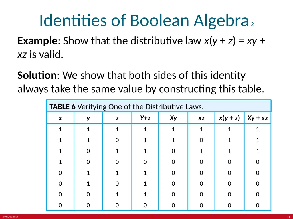
Identities of Boolean Algebra 2 Example: Show that the distributive law x(y + z) = xy + xz is valid.
Solution: We show that both sides of this identity always take the same value by constructing this table. TABLE 6 Verifying One of the Distributive Laws. 11<br>
Solution: We show that both sides of this identity always take the same value by constructing this table. TABLE 6 Verifying One of the Distributive Laws. 11<br>
12
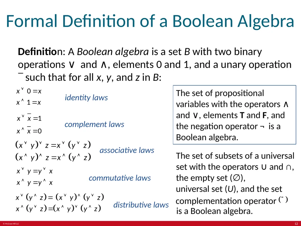
Formal Definition of a Boolean Algebra Definition: A Boolean algebra is a set B with two binary operations ∨ and ∧, elements 0 and 1, and a unary operation such that for all x, y, and z in B: identity laws complement laws associative laws commutative laws distributive laws The set of propositional variables with the operators ∧ and ∨, elements T and F, and the negation operator ¬ is a Boolean algebra. The set of subsets of a universal set with the operators ∪ and ∩, the empty set (∅), universal set (U), and the set complementation operator is a Boolean algebra. 12<br>
13
Representing Boolean Functions Section 12.2 13<br>
14
Section Summary 2 Sum-of-Products Expansions.
Functional Completeness. 14<br>
Functional Completeness. 14<br>
15
Sum-of-Products Expansion 1 Example: Find Boolean expressions that represent the functions F(x, y, z) and (ii) G(x, y, z) in Table 1. Solution: To represent F we need the one term because this expression has the value 1 when x = z = 1 and y = 0. (ii) To represent the function G, we use the sum because this expression has the value 1 when x = y = 1 and z = 0, or x = z = 0 and y = 1. The general principle is that each combination of values of the variables for which the function has the value 1 requires a term in the Boolean sum that is the Boolean product of the variables or their complements. TABLE 1 15<br>
16
Sum-of-Products Expansion 2 Definition: A literal is a Boolean variable or its complement. A minterm of the Boolean variables is a Boolean product , where . Hence, a minterm is a product of n literals, with one literal for each variable.
The minterm has value has value 1 if and only if each is 1.This occurs if and only if = 1 when and when Definition: The sum of minterms that represents the function is called the sum-of-products expansion or the disjunctive normal form of the Boolean function. 16<br>
The minterm has value has value 1 if and only if each is 1.This occurs if and only if = 1 when and when Definition: The sum of minterms that represents the function is called the sum-of-products expansion or the disjunctive normal form of the Boolean function. 16<br>
17
Sum-of-Products Expansion 3 Example: Find the sum-of-products expansion for the function F(x,y,z) = Solution: We use two methods, first using a table and second using Boolean identities. Form the sum of the minterms corresponding to each row of the table that has the value 1. Including a tem for each row of the table for which F(x,y,z) = 1 gives us F(x, y, z) = TABLE 2 17<br>
18
Sum-of-Products Expansion 4 We now use Boolean identities to find the disjunctive normal form of F(x,y,z): 18<br>
19
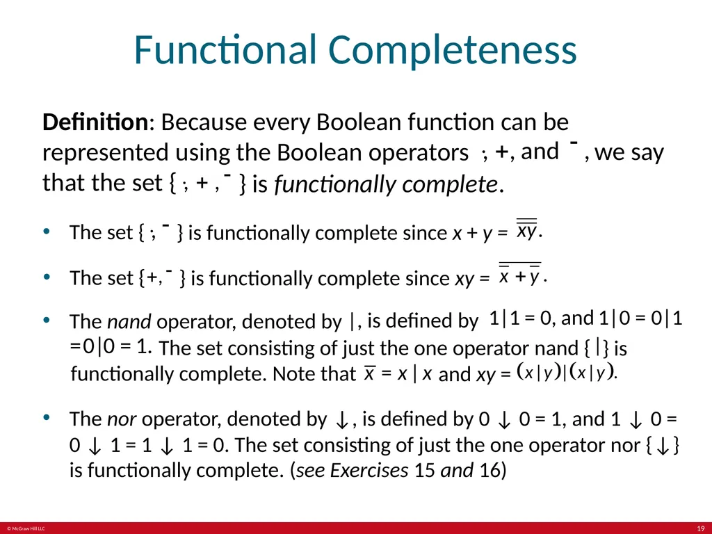
Functional Completeness Definition: Because every Boolean function can be represented using the Boolean operators we say that the set { } is functionally complete. The set { } is functionally complete since x + y = The set { } is functionally complete since xy = The nand operator, denoted by , is defined by The set consisting of just the one operator nand { } is functionally complete. Note that and xy = The nor operator, denoted by ↓, is defined by 0 ↓ 0 = 1, and 1 ↓ 0 = 0 ↓ 1 = 1 ↓ 1 = 0. The set consisting of just the one operator nor {↓} is functionally complete. (see Exercises 15 and 16) 19<br>
20
Logic Gates Section 12.3 20<br>
21
Section Summary 3 Logic Gates.
Combinations of Gates.
Examples of Circuits. 21<br>
Combinations of Gates.
Examples of Circuits. 21<br>
22
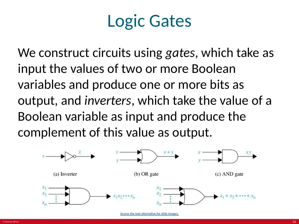
Logic Gates We construct circuits using gates, which take as input the values of two or more Boolean variables and produce one or more bits as output, and inverters, which take the value of a Boolean variable as input and produce the complement of this value as output. Access the text alternative for slide images. 22<br>
23
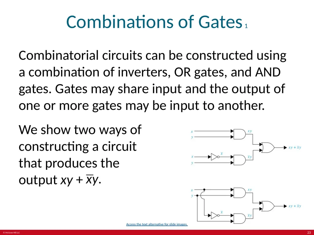
Combinations of Gates 1 Combinatorial circuits can be constructed using a combination of inverters, OR gates, and AND gates. Gates may share input and the output of one or more gates may be input to another. We show two ways of constructing a circuit that produces the output xy + Access the text alternative for slide images. 23<br>
24
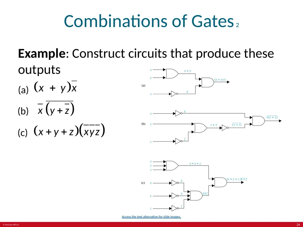
Combinations of Gates 2 Example: Construct circuits that produce these outputs (a) (b) (c) Access the text alternative for slide images. 24<br>
25
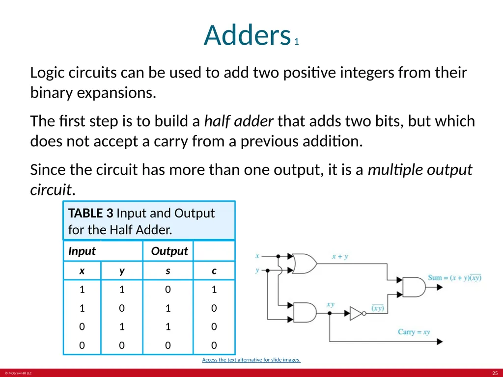
Adders 1 Logic circuits can be used to add two positive integers from their binary expansions.
The first step is to build a half adder that adds two bits, but which does not accept a carry from a previous addition.
Since the circuit has more than one output, it is a multiple output circuit. TABLE 3 Input and Output for the Half Adder. Column 2, input, is divided into two sub-columns as: x and y. Column 3, output, is divided into two sub-columns as: s and c. Access the text alternative for slide images. 25<br>
The first step is to build a half adder that adds two bits, but which does not accept a carry from a previous addition.
Since the circuit has more than one output, it is a multiple output circuit. TABLE 3 Input and Output for the Half Adder. Column 2, input, is divided into two sub-columns as: x and y. Column 3, output, is divided into two sub-columns as: s and c. Access the text alternative for slide images. 25<br>
26
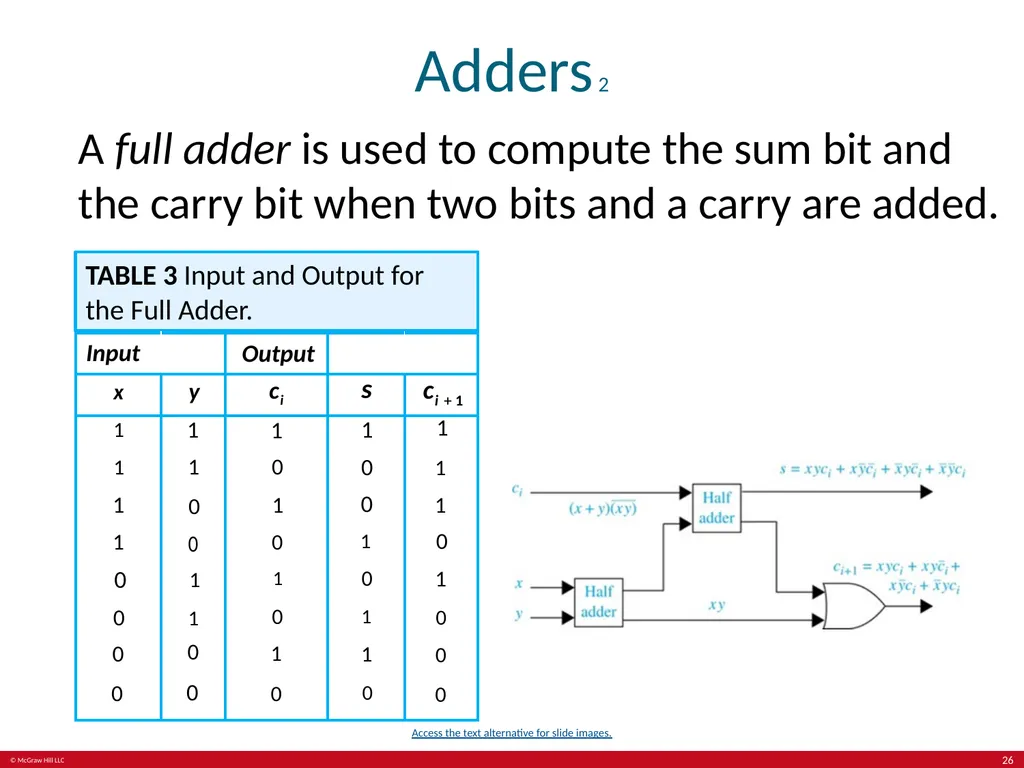
Adders 2 A full adder is used to compute the sum bit and the carry bit when two bits and a carry are added. TABLE 3 Input and Output for the Full Adder. Column 2, input, is divided into two sub-columns as: x and y. Column 3, output, is divided into three sub-columns as: ci, s, and ci plus 1. Access the text alternative for slide images. 26<br>
27
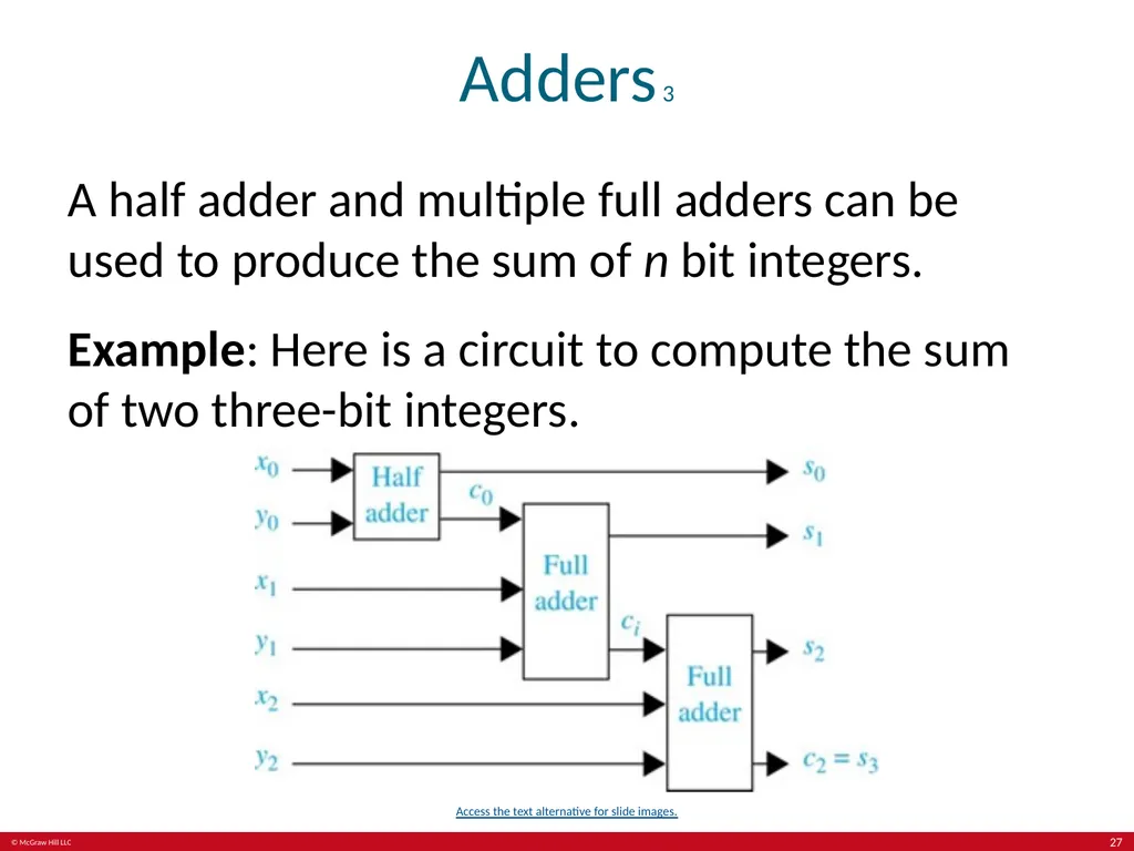
Adders 3 A half adder and multiple full adders can be used to produce the sum of n bit integers.
Example: Here is a circuit to compute the sum of two three-bit integers. Access the text alternative for slide images. 27<br>
Example: Here is a circuit to compute the sum of two three-bit integers. Access the text alternative for slide images. 27<br>
28
End of Main Content © McGraw Hill LLC. All rights reserved. No reproduction or distribution without the prior written consent of McGraw Hill LLC.<br>
29
Accessibility Content:
Text Alternatives for Images 29<br>
30
Logic Gates – Text Alternative Return to parent-slide containing images. Top image: There are three basic logic gates. The first gate is an inverter, which has an input x and an output not x. The second gate is an OR gate, which has two inputs x and y and one output x plus y. The third gate is an AND gate, which has two inputs x and y and one output xy.
Bottom image: There are two gates. The first gate is an AND gate that has n inputs, x subscript 1, x subscript 2 and so on to x subscript n, and one output, x subscript 1, x subscript 2 and so on, x subscript n. The second gate is an OR gate that has n inputs, x subscript 1, x subscript 2 and so on to x subscript n, and one output, x subscript 1 plus x subscript 2 and so on plus x subscript n. Return to parent-slide containing images. 30<br>
Bottom image: There are two gates. The first gate is an AND gate that has n inputs, x subscript 1, x subscript 2 and so on to x subscript n, and one output, x subscript 1, x subscript 2 and so on, x subscript n. The second gate is an OR gate that has n inputs, x subscript 1, x subscript 2 and so on to x subscript n, and one output, x subscript 1 plus x subscript 2 and so on plus x subscript n. Return to parent-slide containing images. 30<br>
31
Combinations of Gates 1 – Text Alternative Return to parent-slide containing images. Circuit 1. There is a logical circuit consisting of 1 inverter, 2 AND gates, and 1 OR gate. The circuit has 4 inputs, 2 x and 2 y, and 1 output. The first pair of x and y is considered as an input for the first AND gate, the output is x, y. The second x input passes through the inverter with the result of not x. Together with the second y, it is considered as an input for the second AND gate. The output is not x, y. The 2 outputs, x, y and not x, y, are in turn considered as inputs for the OR gate. The output is x, y plus not x, y. Circuit 2 contains the same gates and inverter as the first circuit. There are only two initial inputs for this circuit, x and y. Each of these inputs is divided into 2 branches so that the first pair of x and y branches passes through the first AND gate. The output is x, y. The second x branch passes through the inverter with not x output and together with the second y branch passes through the second AND gate. The output is not x, y. The two outputs, x, y, and not x, y, are considered as inputs for the OR gate. The output is x, y plus not x, y. Return to parent-slide containing images. 31<br>
32
Combinations of Gates 2 – Text Alternative Return to parent-slide containing images. Circuit A. There is a logical circuit consisting of 1 inverter, 1 AND gate, and 1 OR gate. There are 3 inputs, x, y and x. The first x together with y enters the OR gate, the output is x plus y. The second x passes through the inverter resulting in not x. Together with the output of the OR gate, it is considered as input for the AND gate. The output is left parenthesis x plus y right parenthesis not x. Circuit B. The circuit consists of 3 inverters, 1 OR gate, and 1 AND gate. There are 3 inputs, x, y, and z. x passes through the inverter and results in not x. z also passes through the second inverter and results in not z. Together with y, not z enters the OR gate. The output is y plus not z. This output, in turn, enters the third inverter, and results in not left parenthesis y plus not z right parenthesis. This output together with not x is considered as the input for the AND gate. The output is not x, not left parenthesis y plus not z right parenthesis. Circuit C. The circuit consists of 3 inverters, 2 AND gates, and 1 OR gate. There are 6 inputs, x, y, z, x, y, and z. The first set of x, y, and z enters the OR gate and results in x plus y plus z. Each of the elements of the second x, y, z set passes through the inverter, producing separately not x, not y, and not z. These 3 outputs are considered as the input for the first AND gate. The output is not x, not y, not z. This output, together with the output of the OR gate, x plus y plus z, enters the second AND gate. The output is left parenthesis x plus y plus z right parenthesis not x, not y, not z. Return to parent-slide containing images. 32<br>
33
Adders 1 – Text Alternative Return to parent-slide containing images. There is a logical circuit consisting of 1 inverter, 2 AND gates, and 1 OR gate. There are two inputs, x and y. Each of these inputs is divided into 2 branches so that the first pair of x and y branches passes through the OR gate. The output is x plus y. The second pair of x and y branches passes through the first AND gate. The output is x, y, that is divided into 2 branches so that the first x, y passes through the inverter with the output not left parenthesis x, y right parenthesis. Together with the result of the OR gate, it is considered as an input for the second AND gate. The second x, y is the first output of the circuit, and it is labeled Carry equals x, y. The second output of the circuit is the result of the second AND gate, which is Sum equals left parenthesis x plus y right parenthesis, not left parenthesis x, y right parenthesis. Return to parent-slide containing images. 33<br>
34
Adders 2 – Text Alternative Return to parent-slide containing images. There is a logical circuit consisting of 1 OR gate and 2 Half adders. The circuit has 3 inputs c subscript i, x, y. Input c subscript i is left parenthesis x plus y right parenthesis not left parenthesis x, y right parenthesis. C subscript i is the first input of the first half adder. A pair of x and y is the input of the second half adder. The first output of the second Half adder is the second input of the first Half adder. And the second output is x, y, that goes to the OR gate. The first output of the first Half adder is the first output of the circuit, that is labeled s equals x, y, c subscript i plus x, not y, not c subscript i plus not x, y, not c subscript i plus not x, not y, c subscript i. The second output of the first Half adder goes to the OR gate. The result of the OR gate is the second output of the circuit, that labeled c subscript i plus one equals x, y, c subscript i plus x, y, not c subscript i plus x, not y, c subscript i plus not x, y, c subscript i. Return to parent-slide containing images. 34<br>
35
Adders 3 – Text Alternative Return to parent-slide containing images. There is a logical circuit consisting of 1 Half adder and 2 Full adders. The circuit has 6 inputs. x subscript 0 to x subscript 2, y subscript 0, and y subscript 1. And it has 4 outputs. The first set of x subscript 0 and y subscript 0 goes to the first Half adder, the first output of which is s subscript 0 and it is the first output of the circuit. And the second output of the first Half adder is c subscript 0, it is considered as an input for the first Full adder. The second set of x subscript 1 and y subscript 1 goes to the first Full adder, the first output of which is s subscript 1 and it is the second output of the circuit. And the second output of the first Full adder is c subscript i that is considered as an input for the second Full adder. The third set of x subscript 2 and y subscript 2 goes to the second Full adder. The outputs of the second Full adder are s subscript 2 and c subscript 2 equals s subscript 3, that are the third and the fourth outputs of the circuit. Return to parent-slide containing images. 35<br>