Buck boost converter GT ECE academic lab Slides by Zachary Chan Overview Type of switch mode power converter, meaning it had a switching transistor Combines benefits from buck and boost converters Can increase or decrease the output voltage
"Buck boost converter GT ECE academic lab Slides by" is the property of its rightful owner. Permission is granted to
download and print the materials on this website for personal, non-commercial use only, and to display it
on your personal computer provided you do not modify the materials and that you retain all copyright
notices contained in the materials. By downloading content from our website, you accept the terms of this
agreement.
Overview Type of switch mode power converter, meaning it had a switching transistor
Combines benefits from buck and boost converters
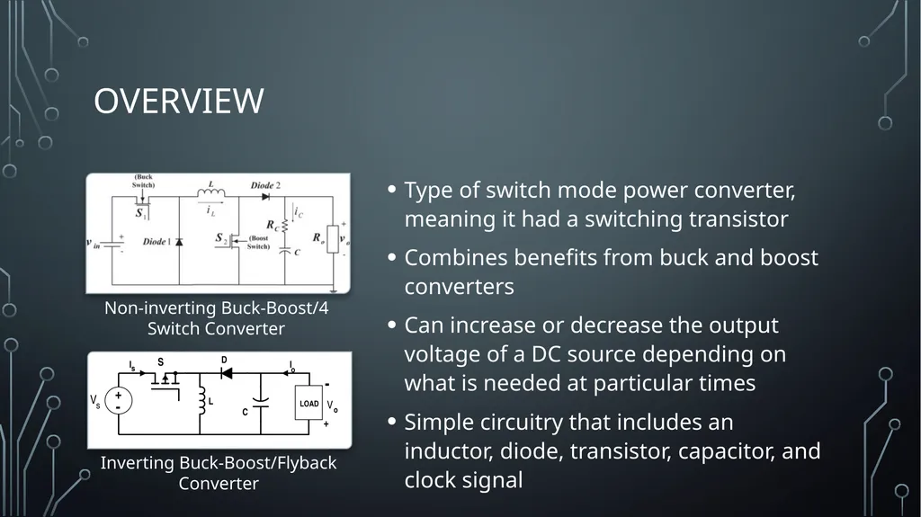
Can increase or decrease the output voltage of a DC source depending on what is needed at particular times
Simple circuitry that includes an inductor, diode, transistor, capacitor, and clock signal Non-inverting Buck-Boost/4 Switch Converter Inverting Buck-Boost/Flyback Converter<br>
03
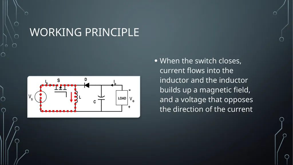
Working Principle When the switch closes, current flows into the inductor and the inductor builds up a magnetic field, and a voltage that opposes the direction of the current<br>
04
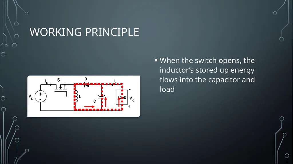
Working Principle When the switch opens, the inductor’s stored up energy flows into the capacitor and load<br>
05
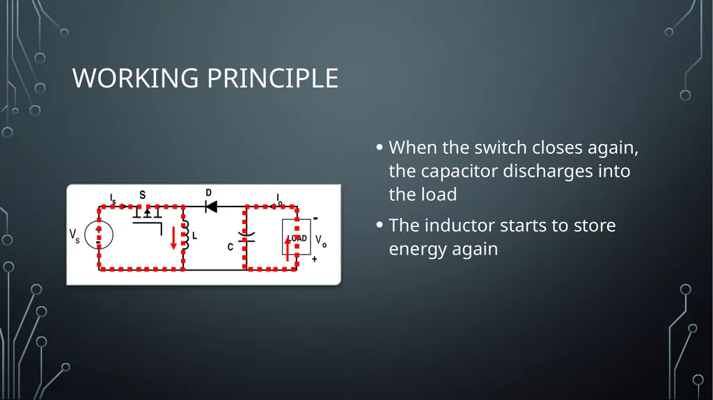
Working Principle When the switch closes again, the capacitor discharges into the load
The inductor starts to store energy again<br>
06
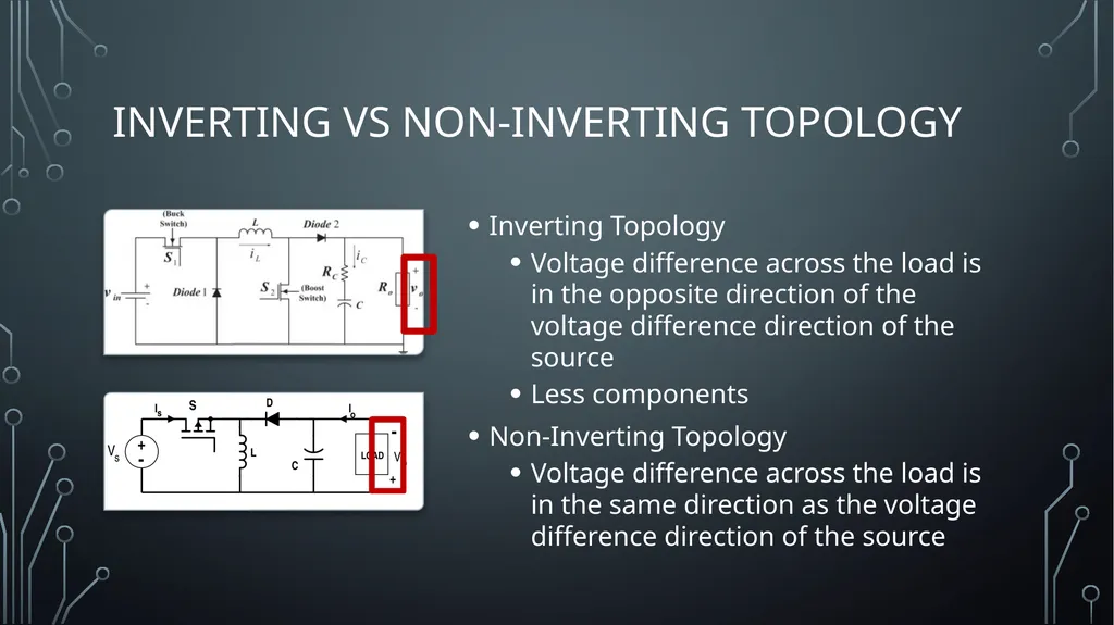
Inverting vs non-inverting Topology Inverting Topology
Voltage difference across the load is in the opposite direction of the voltage difference direction of the source
Less components
Non-Inverting Topology
Voltage difference across the load is in the same direction as the voltage difference direction of the source<br>
07
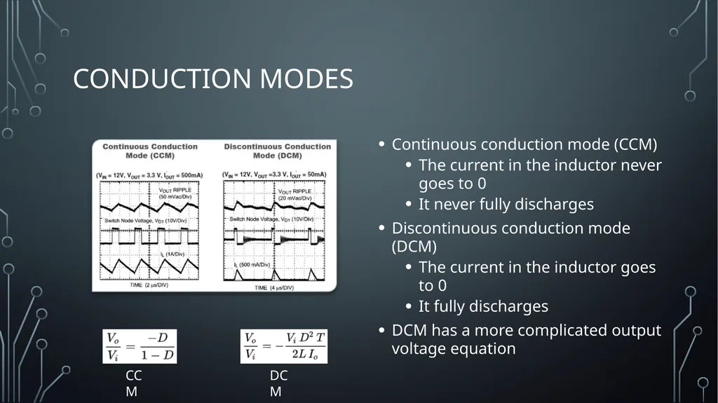
Conduction modes Continuous conduction mode (CCM)
The current in the inductor never goes to 0
It never fully discharges
Discontinuous conduction mode (DCM)
The current in the inductor goes to 0
It fully discharges
DCM has a more complicated output voltage equation CCM DCM<br>
08
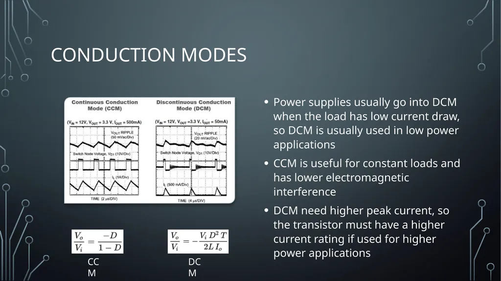
Conduction modes Power supplies usually go into DCM when the load has low current draw, so DCM is usually used in low power applications
CCM is useful for constant loads and has lower electromagnetic interference
DCM need higher peak current, so the transistor must have a higher current rating if used for higher power applications CCM DCM<br>
09
Clock Signal Varying the duty cycle of the clock signal varies the output voltage
This is what determines whether the converter is in buck or boost mode
When the duty cycle is less than 0.5, the converter is in buck mode and when it is greater than 0.5, it is in boost mode
A control signal can be used to determine whether the converter must be in buck or boost mode if the voltage of the source changes<br>